
Subscribe to Our Youtube Channel
Related Manuals for Srne HT4830S80-145


Summary of Contents for Srne HT4830S80-145
- Page 1 Horizontal Type All-in-one Solar Charger Inverter User Manual Product models: HT4830S80 -145 | HT4840S80 -145 | HT4850S80 -145...
- Page 2 Important safety instructions Please keep this manual for future reference The user manual contains all safety, installation, and operation instructions for the HT series all-in-one solar energy storage inverter controller. Please read all instructions and precautions in the manual carefully before installation and use. ...
-
Page 3: Table Of Contents
Table of Contents 1. Basic Information ..................4 1.1 Product overview and features ............4 1.2 Basic system introduction ..............5 1.3 Product characteristics ................ 7 2. Installation Instructions................8 2.1 Installation considerations ..............8 2.2 Wiring specifications and circuit breaker selection......9 2.3 Installation and wiring .............. -
Page 4: Basic Information
1. Basic Information 1.1 Product overview and features HT series is a new hybrid PV energy storage inverter controller integrating PV energy storage, mains charging and storage and AC sine wave output. Using DSP control through advanced control algorithms, it comes with high response speed, high reliability, high industrialization standard and other characteristics. -
Page 5: Basic System Introduction
6. ON/OFF rocker switch controls AC output. 7. Power saving mode reduces no-load loss. 8. Intelligent variable speed fan ensures efficient heat dissipation, and thereby extends system life. 9. It comes with double lithium battery activation modes: mains and PV, and supports lead- acid battery and lithium battery access. - Page 6 All-in-one Solar Energy Storage Inverter Controller...
-
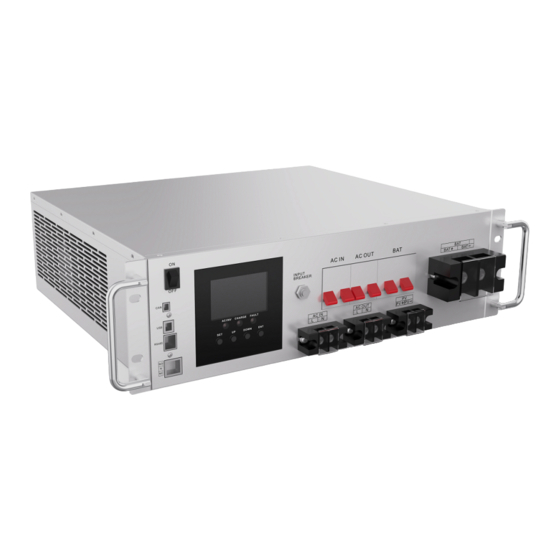
Page 7: Product Characteristics
1.3 Product characteristics ON/OFF rocker switch AC input port CAN communication port AC input air switch USB communication port AC output port RS485 communication port AC output air switch Dry node port PV port LCD screen Battery air switch Indicator Grounding screw hole Touch button Battery port... -
Page 8: Installation Instructions
2. Installation Instructions 2.1 Installation considerations Read this manual carefully and familiarize yourself with the installation procedures before installing. Be very careful when installing the battery, and wear protective goggles when installing lead-acid liquid battery. Once in contact with the battery acid, rinse the contact part with water in time. -
Page 9: Wiring Specifications And Circuit Breaker Selection
Maximum PV battery Model or circuit breaker input current specification wire diameter 10mm 2 /7AWG HT4830S80-145 2P 63A 10mm 2 /7AWG HT4840S80-145 2P 63A 10mm 2 /7AWG HT4850S80-145 2P 63A Note: The voltage must not exceed the maximum PV input open circuit voltage of 145V when connected in series. - Page 10 Maximum bypass Recommended air switch or battery Model input current circuit breaker specification wire diameter 10mm 2 /7AWG HT4830S80-145 2P 40A 10mm 2 /7AWG HT4840S80-145 2P 40A 10mm 2 /7AWG HT4850S80-145 2P 40A Note: The corresponding circuit breaker is available at the mains input connection and may not be added.
-
Page 11: Installation And Wiring
Note: The wiring diameter is for reference only. If the distance between the PV array and the all-in-one machine or between the all-in-one machine and the battery is long, using a thicker wire will reduce the voltage drop and improve system performance. Note: The above wiring diameters and circuit breakers are only for recommendation. - Page 12 Step 2: Remove the terminal protection cover All-in-one Solar Energy Storage Inverter Controller...
- Page 13 Step 3: Wiring AC input/output wiring method: Before AC input/output wiring, disconnect the circuit breaker first, and confirm whether the wires used are thick enough. Please refer to Section 2.2 Wiring Specifications and Circuit Breaker Selection". Correctly connect the AC input live and neutral wires according to the wire sequence and terminal locations shown below.
- Page 14 L: Live wire N: Neutral wire Correctly connect the AC output live and neutral wires according to the wire sequence and terminal locations shown below, and connect the earth wire to the grounding screw hole through the O-type terminal. L: Live wire N: Neutral wire Note: Try to use a thick earth wire (wire cross-sectional area is not less than 4mm2), the grounding point should be as close as possible to the machine, and the shorter the grounding...
- Page 15 locations shown below. The PV ports on the machine are preferred for wiring. PV+:PV input positive PV-:PV input negative BAT wiring method: Before wiring, disconnect the circuit breaker first, and confirm whether the wires used are thick enough. Please refer to Section 2.2 Wiring Specifications and Circuit Breaker Selection .
- Page 16 BAT+: Battery positive BAT-: Battery negative Warnings: The mains input, AC output and PV array will generate high voltages, so be sure to disconnect the circuit breaker or fuse before wiring; During wiring, be sure to be careful; during wiring, do not close the circuit breaker or fuse, and ensure that the + and - pole lead connections of each component are correct;...
- Page 17 Step 6: Start the all-in-one machine First of all, close the circuit breaker at the battery end; secondly, turn the rocker switch on the left side of the machine to the ON state, and AC/INV indicator flashing means that the inverter is working normally; then, close the circuit breaker of the PV array and mains power;...
-
Page 18: Operating Mode
3. Operating Mode 3.1 Charging mode 1. PV priority: PV system is prioritized for battery charging, only when the PV fails, mains charging is activated. Making full use of solar energy to generate power during the day and switching to mains charging at night keep the batteries charged. This mode is applicable to the areas where the grid is relatively stable and electricity is more expensive. -
Page 19: Output Mode
4. Only Solar: battery is only charged by PV system and mains charging is not activated. This is the most energy-efficient mode, with all battery power coming from solar energy, usually used in areas with good light conditions. 3.2 Output mode PV priority mode: both PV and battery power the loads. - Page 20 Inverter priority mode: Switch to mains only when the battery is under voltage. This mode maximizes the use of DC power and is suitable for areas where the grid is stable. All-in-one Solar Energy Storage Inverter Controller...
-
Page 21: Lcd Screen Operating Instructions
4. LCD Screen Operating Instructions 4.1 Operation and display panel The operation and display panel is shown below and consists of 1 LCD screen, 3 indicators and 4 operation buttons. Operation buttons introduction Functional buttons Description Enter/exit setup menu Previous option DOWN Next option Under the Setup menu, the OK/Enter option... - Page 22 Icons Function Icons Function Indicates that the AC input end Indicates that the inverter has been connected to the grid circuit is working Indicates that the AC input mode in Indicates that the machine is APL mode (wide voltage range) working in Bypass mode Indicates that the PV input end Indicates that the AC output...
- Page 23 Indicates that the current battery Indicates that the machine type of the machine is a lead- has an alarm acid battery Indicates that the battery is in Indicates that the machine is charging state in a faulty state Indicates that the AC/PV Indicates that the machine is charging circuit is working in setup mode...
-
Page 24: Setup Parameters Description
Real-time data viewing method On the LCD main screen, press the “UP” and “DOWN” buttons to scroll through the real-time data of the machine. Parameters Parameters on the left side of the in the Parameters on the right Page screen middle of side of the screen the screen... - Page 25 “ENT” button to enter the parameter editing mode, and the value of the parameter is flashing. Adjust the value of the parameter with the “UP” and “DOWN” buttons. Finally, press the “ENT” button to complete the parameter editing and return to the parameter selection state. Parameter Parameter Settings...
- Page 26 Parameter Parameter Settings Description name PV priority charging; only when the PV [06] CSO charging fails, the mains charging is started. Mains priority charging; only when the mains [06] CUB charging fails, the PV charging is started. PV and Mains hybrid charging; PV charging is a priority, and when the PV energy is insufficient, Charger the Mains charging supplements.
- Page 27 Parameter Parameter Settings Description name [08] N13/N14 Ternary lithium battery; which is adjustable. Battery boost Boost charge voltage setting; the setting range [09] 57.6V charge is 48V~58.4V, with step of 0.4V; it is valid for default voltage user-defined battery and lithium battery. Boost charge maximum time setting, which means the maximum charging time to reach the set voltage of parameter [09] during...
- Page 28 Parameter Parameter Settings Description name Battery discharge limit voltage; when the Battery battery voltage is lower than the point, the discharge [15] 40V default output is turned off immediately; the setting limit voltage range is 40V~52V, with a step of 0.4V. It is valid for user-defined battery and lithium battery.
- Page 29 Parameter Parameter Settings Description name Automatic restart when overload is enabled. If an overload occurs and the output is turned off, [23] ENA default the machine will restart after a delay of 3 minutes. After it reaches 5 cumulative times, the machine will not restart.
- Page 30 Parameter Parameter Settings Description name [ 32 ] SLA Communication Connect to our remote Type of default monitoring module (WiFi, GPRS...) communication connection [ 32 ] BNS Communication connection battery BMS [ 33 ] PAC Pace BMS Protocol (valid when parameter [32] is set to BNS) default Ratar BMS Protocol (valid when parameter...
-
Page 31: Battery Type Parameters
4.3 Battery type parameters For Lead-acid Battery : Battery type Sealed lead Colloidal lead Vented lead User-defined acid battery acid battery acid battery (User) (SLD) (GEL) (FLD) Parameters Overvoltage disconnection voltage 36~60V 58.4V 56.8V 59.2V Equalizing charge voltage (Adjustable) 36~60V 57.6V 56.8V 58.4V... - Page 32 For Lithium Battery : Lithium Lithium Lithium Ternary Ternary Battery type iron iron iron User- lithium lithium phosphat phosphat phosphat defined battery battery e battery e battery e battery (User) Parameters (N13) (N14) (L16) (L15) (L14) Overvoltage disconnection voltage 36~60V Equalizing charge voltage (Adjustable)
-
Page 33: Other Functions
5. Other functions 5.1 Dry node Working principle: This dry node can control the ON/OFF of the diesel generator to charge the battery. ① Normally, the terminals are that the NC-N point is closed and the NO-N point is open; ② When the battery voltage reaches the low voltage disconnection point, the relay coil is energized, and the terminals turn to that the NO-N point is closed while NC-N point is open. -
Page 34: Protections
6. Protection 6.1 Protections provided Protections Description PV current/power When charging current or power of the PV array configured exceeds limiting protection the PV rated, it will charge at the rated. At night, the battery is prevented from discharging through the PV PV night reverse- module because the battery voltage is greater than the voltage of PV current protection... - Page 35 PV reverse polarity When the PV polarity is reversed, the machine will not be damaged. protection AC reverse Prevent battery inverter AC current from being reversely input to protection Bypass. Bypass over current Built-in AC input overcurrent protection circuit breaker. protection When the discharge output current of the battery is greater than the Battery input over...
-
Page 36: Fault Codes Meaning
6.2 Fault code meaning Whether it Fault code Fault name affects the Description output or not BatVoltLow Battery undervoltage alarm 【01】 Battery discharge average current BatOverCurrSw 【02】 overcurrent software protection BatOpen Battery not-connected alarm 【03】 BatLowEod Battery undervoltage stop discharge alarm 【04】... - Page 37 6.3 Handling measures for part of faults Faults Handling measures Check if the battery air switch or the PV air switch has been closed; No display on the screen if the switch is in the "ON" state; press any button on the screen to exit the screen sleep mode.
-
Page 38: System Maintenance
7. System Maintenance In order to maintain optimal long-lasting performance, it is recommended that the following items be checked twice a year. 1. Confirm that the airflow around the all-in-one machine will not be blocked and remove any dirt or debris from the head sink. 2. -
Page 39: Technical Parameters
8. Technical parameters Model HT4830S80-145 HT4840S80-145 HT4850S80-145 Mains mode Rated input 220/230Vac voltage Input (170Vac~280Vac) ±2% voltage (90Vac-280Vac)±2% range Frequency 50Hz/ 60Hz (automatic detection) Frequency 47±0.3Hz ~ 55±0.3Hz (50Hz); range 57±0.3Hz ~ 65±0.3Hz (60Hz); Overload/sh ort circuit Circuit breaker protection Efficiency >95%... - Page 40 6000VA Peak power 8000VA 10000VA Loaded motor capacity Output short circuit Circuit breaker protection Bypass circuit breaker specification Rated battery input 48V (minimum starting voltage 44V) voltage Battery 40.0Vdc~60Vdc ± 0.6Vdc (undervoltage alarm / shutdown voltage / overvoltage alarm / voltage overvoltage recovery...LCD screen can be set) range...
- Page 41 output power PV charge current 0-80A range (settable) Charge short circuit BAT circuit breaker and fuse protection Wiring Reverse polarity protection protection Hybrid charging Max charger current specifications (AC charger+PV charger) Max charger current(can be 0- 140 A set) Certified specification Specification CE(IEC 62109-1) certification...
Need help?
Do you have a question about the HT4830S80-145 and is the answer not in the manual?
Questions and answers