
Related Manuals for CAME LUNA


Summary of Contents for CAME LUNA
- Page 1 SIRENA A LED PER CENTRALI ANTIFURTO 11 9 R V46 LUNA MANUALE D’INSTALLAZIONE Italian o English Fran ç ais Русски й Italiano...
-
Page 2: Legenda Simboli
Ogni installazione e uso difformi da quanto indicato in questo manuale sono da considerarsi vietate. Descrizione sirena La sirena per centrali antifurto LUNA è progettata e costruita interamente da CAME Cancelli Automatici S.p.A. in conformità alle seguenti normative: EN 50130-4 e EN 50131-4. - Page 3 Dati tecnici Alimentazione 12 V-15 V DC Assorbimento 1,5 A Assorbimento a riposo 30 mA Cono 8 Ω magnetodinamico Livello pressione sonora 108 dB (A) ad 1 m Batteria 12V 2,2 Ah Peso (batteria esclusa) 2,5 kg Temperatura di esercizio -25°C ÷...
- Page 4 Componenti principali 1 -Base sirena 2 -Tamper antistrappo 3 -Scheda elettronica 4 -Supporto per alloggiamento batteria 5 -Cono 6 -Sostegno coperchio 7 -Griglia di protezione 8 -Coperchio 9 -Finestra lampeggiatore 10 -Sensore antischiuma 11 -Passacavo Dimensioni (mm) I dati e le informazioni indicate in questo manuale sono da ritenersi suscettibili di modifica in qualsiasi momento e senza obbligo di preavviso.
-
Page 5: Installazione
Installazione L’installazione deve essere effettuata da personale qualificato ed esperto e nel pieno rispetto delle normative vigenti. Verifi che preliminari Prima di procedere all’installazione è necessario: • Verificare che il punto di fissaggio della sirena sia in una zona protetta dagli urti, che le superfici di ancoraggio siano solide, e che il fissaggio venga fatto con elementi adatti (viti, tasselli, ecc) alla superficie. - Page 6 Procedura di montaggio Per una corretta installazione, seguire la procedura di seguito riportata. Prevedere una canalina sul punto previsto di fissaggio della sirena per il passaggio dei cavi dalla centrale. Servirsi della dima Forare i punti in dotazione per contrassegnati. segnare i punti di fissaggio della sirena.
- Page 7 Togliere il coperchio della sirena svitando la vite posizionata frontalmente Togliere la griglia di protezione dal fondo della sirena svitando le 4 viti. Nota: per praticità, mettere la griglia all’interno del coperchio. I dati e le informazioni indicate in questo manuale sono da ritenersi suscettibili di modifica in qualsiasi momento e senza obbligo di preavviso.
- Page 8 Forare sulla parte superiore della base in uno o più punti (a seconda del numero di cavi da passare) contrassegnati. Passacavo Infilare il passacavo (i passacavi) in dotazione nel foro (nei fori). I dati e le informazioni indicate in questo manuale sono da ritenersi suscettibili di modifica in qualsiasi momento e senza obbligo di preavviso.
- Page 9 Controllare che la superficie di appoggio del fondo della sirena sia piana in modo da non compromettere il corretto funzionamento del Tamper antistrappo. Livella Tamper antistrappo Posizionare la base in orizzontale servendosi della livella incorporata e fissarla con elementi adatti al tipo di superficie.
- Page 10 Inserire la batteria (non inclusa) nel fondo della sirena, eseguire i collegamenti elettrici (vedi capitolo cablaggi) e i settaggi (vedi par. selezione funzioni). Attenzione: lasciare il dip 1 (LOCK) in posizione ON. Dopo aver eseguito i collegamenti elettrici anche dalla centrale, posizionare il dip 1 (LOCK) in OFF.
- Page 11 Inserire e fissare la griglia di protezione con le 4 viti. Infine, inserire e fissare il coperchio esterno. I dati e le informazioni indicate in questo manuale sono da ritenersi suscettibili di modifica in qualsiasi momento e senza obbligo di preavviso.
- Page 12 Descrizione scheda Componenti principali 1 - Connettore per cavi batteria e cono 2 - Interruttore antistrappo e antischiuma 3 - Interruttore antiapertura 4 - Connettore per cavi LED di segnalazione 5 - Dip-switch 6 - Morsettiera di alimentazione e accessori 7 - Fusibile di protezione scheda F 3,15A 8 - Fusibile di protezione inversione polarità...
- Page 13 Selezioni funzioni (Dip-switch) Posizione dip 3 e 4 Tempo allarme sec. 3 OFF 4 OFF 3 ON 4 OFF 3 OFF 4 ON 180 (default) 3 ON 4 ON Default (ON) blocco sirena; (OFF) dopo 30 secondi, la sirena è pronta per essere attivata dalla centrale. Default (ON) i LED lampeggiano fino al tempo di allarme impostato;...
- Page 14 Cablaggi Tipo e sezione cavi Lunghezza cavo Lunghezza cavo Lunghezza cavo Collegamento Tipo cavo 1 < 10 m 10 < 20 m 20 < 30 m 2 x 0,5 mm 2 2 x 0,75 mm 2 2 x 1,0 mm 2 Alimentazione dalla centrale 2 x 0,22 mm 2 2 x 0,5 mm 2...
- Page 15 Alimentazione scheda e accessori (necessari) TAMPER : Collegamento agli interruttori tamper Ingresso di comando sirena. Un positivo (+) collegato al C, blocca la sirena. Un negativo (-) collegato al C, attiva la sirena. -, + : Alimentazione 12V - DC. CENTRALE Batteria 12V DC - 2.2Ah...
- Page 16 Dispositivi e segnalazioni (opzionali) LED1 : Ingresso per comando LED posizionati frontalmente. Un negativo (-) collegato all’ingresso, i LED si accendono. LED2 : Ingresso per comando LED posizionati in basso. Un negativo (-) collegato all’ingresso, i LED si accendono. Negativo scheda da usare per l’ingresso LED. LOCK : Ingresso di blocco.
- Page 17 CENTRAL Blocco sirena da esterno con chiave personalizzata I dati e le informazioni indicate in questo manuale sono da ritenersi suscettibili di modifica in qualsiasi momento e senza obbligo di preavviso.
- Page 18 N.B.: se si desidera che i LED1 e/o LED2 si accendono dopo un comando di attivazione del sistema di allarme, dopo un rilevamen- to di presenza in un determinato luogo, per rilevamento di gas etc., collegare l’ingresso LED1 o LED2 con il negativo (-) della scheda mediante un relè.
-
Page 19: Smaltimento Dell'imballo
Ambientale certificato e conforme alla norma UNI EN ISO 14001 a garanzia del rispetto e della tutela dell’ambiente. Vi chiediamo di continuare l’opera di tutela dell’ambiente, che CAME considera uno dei fondamenti di sviluppo delle proprie strategie operative e di mercato, semplicemente osservando brevi indicazioni in materia di smaltimento: SMALTIMENTO DELL’IMBALLO... - Page 20 (+7) 495 739 00 69 - (+7) 495 739 00 69 (ext. 226) CAME United Kingdom Ltd. CAME United Kingdom Ltd. GREAT BRITAIN PORTUGAL CAME Portugal - Ucj Portugal Unipessoal Lda CAME Portugal - Ucj Portugal Unipessoal Lda Nottingham Nottingham Barreiro Barreiro...
- Page 21 LED SIREN FOR BURGLARPROOF CONTROL UNITS 1 19 R V 4 6 E N LUNA INSTALLATION MANUAL English...
-
Page 22: Siren Description
Every installation and use other than that specified in this manual is forbidden. Siren description The LUNA burglarproof control unit siren is designed and built entirely by CAME Cancelli Automatici S.p.A. in com- pliance with the following regulations:EN 50130-4 and EN 50131-4. - Page 23 Technical data Power supply 12 V-15 V DC Power draw 1.5 A Power draw when idle 30 mA Cone 8 Ωdynamic magnet Level of sound pressure 108 dB (A) ad 1 m Battery 12V 2.2 Ah Weight (battery not included) 2.5 kg Working temperature -25°C ÷...
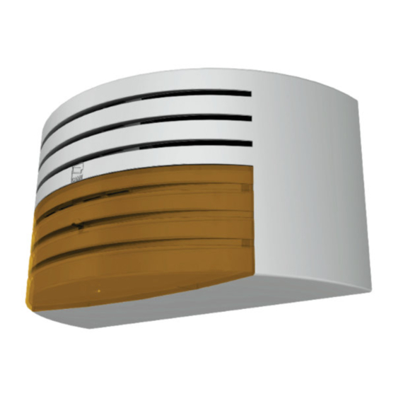
- Page 24 Main component parts 1 - Siren base 2 - Rip-proof tamper switch 3 - Electronic card 4 - Support for battery housing 5 - Cone 6 - Cover support 7 - Protective grille 8 - Cover 9 - Flasher window 10 - Foam-proof sensor 11 - Cable ring Dimensions...
-
Page 25: Installation
Installation Installation must be carried by skilled, qualified technicians in accordance with current regulations. Preliminary checks Before beginning to install, the following is necessary: Make sure that the point where the siren is anchored is free from any impacts, and that the surface is solid and that proper tools and materials are used (i.e. - Page 26 Mounting procedure For proper installation, follow the procedure described below. Set up a conduit at the siren's anchoring point for cables to the control unit to pass through. Use the stencil Perforate the marked to mark the siren points. anchoring points. The data and information in this manual may be changed at any time and without prior notice.
- Page 27 Remove the siren cover by unscrewing the front screw. Remove the protective grille from the back of the siren by unscrewing the 4 screws. Note: for practical reasons, place the grille inside the cover. The data and information in this manual may be changed at any time and without prior notice.
- Page 28 Perforate the top part of the base (depending on the number of cables you have to pass through) where marked. Cable ring Insert the supplied cable ring (rings) into the hole (holes). The data and information in this manual may be changed at any time and without prior notice.
- Page 29 Check that the resting surface at the bottom of the siren is flat so as not to compromise the proper functioning of the Rip-proof tamper. Level Rip-proof tamper Place the base horizontally using the built-in level and secure it properly depending on the type of surface.
- Page 30 Insert battery (not included) into the bottom of the siren, make any electrical connections (see wiring chapter) and necessary settings (see function selection paragraph). Warning: leave DIP-switch 1 (LOCK) in the ON position. After completing the electrical connections also from the control unit, position Dip-switch 1 (LOCK) to OFF.
- Page 31 Insert and secure the protective grill using the 4 screws. Finally, insert and secure the outer cover. The data and information in this manual may be changed at any time and without prior notice.
-
Page 32: Card Description
Card description Main component parts 1 - Connector for battery cables and cone 2 - Rip-proof and foam-proof switch 3 - Open-proof switch 4 - LED warning lights cable connector 5 - Dip-switches 6 - Power supply and accessories terminals 7 - Protective fuse for the F 3.15A card 8 - Protective fuse for inverting F 3.15A battery polarity 9 - LED warning lights... - Page 33 Functions selection (Dip-switches) Position Dip-switches Alarm time in seconds 3 and 4 3 OFF 4 OFF 3 ON 4 OFF 3 OFF 4 ON 180 (default) 3 ON 4 ON Default (ON) siren block; (OFF) after 30 seconds, the siren is ready for activation by the control unit. Default (ON) the LEDs flash until the set alarm time;(OFF) the LEDs flash until the N.C.
- Page 34 Wiring Cable type and section Cable length Cable length Cable length Connection Cable type 1 < 10 m 10 < 20 m 20 < 30 m 2 x 0.5 mm 2 2 x 0.75 mm 2 2 x 1.0 mm 2 Power supply to control unit 2 x 0.22 mm 2 2 x 0.5 mm 2...
- Page 35 Power supply to card and accessories (required) TAMPER: Connection to tamper switches Siren command input.A positive (+) connected to C, blocks the siren. A negative (-) connected to C, activates the siren. -, + : Power supply 12V -DC. CONTROL UNIT Battery 12V DC - 2.2Ah Black...
- Page 36 Warning devices (optional) LED 1 : Command input for LE Ds positionedfrontally. With a negative (-) connected to the input, the LEDs turn on. LED 2 : Command input for LEDs positioned below. With a negative (-) connected to the input, the LEDs turn on. Card negative to be used for LED input.
- Page 37 CENTRAL External siren block with customised key The data and information in this manual may be changed at any time and without prior notice.
- Page 38 N.B.: if you wish LED 1 and/or LED 2 to turn on after each alarm system activation com- mand, or motion detection in a certain spot, for gas detection, etc., connect the LED 1 or LED 2 inputs with the card negative (-) via a relay.
-
Page 39: Dismantling And Disposal
UNI EN ISO 14001 standard to ensure environmental protection. Please help us to safeguard the environment. At CAME we believe this to be one of the fundamentals in its market operations and development strategies. Just follow these short disposal instructions: DISPOSING OF THE PACKAGING The components of the packaging (i.e. - Page 40 (+7) 495 739 00 69 - (+7) 495 739 00 69 (ext. 226) CAME United Kingdom Ltd. CAME United Kingdom Ltd. GREAT BRITAIN PORTUGAL CAME Portugal - Ucj Portugal Unipessoal Lda CAME Portugal - Ucj Portugal Unipessoal Lda Nottingham Nottingham Barreiro Barreiro...
- Page 41 SIRÈNE A LED POUR CENTRALES ANTIVOL 11 9 R V4 6 F R LUNA MANUEL D’INSTALLATION Français...
-
Page 42: Destination D'utilisation
Toute installation et utilisation non conformes à ce qui est indiqué dans ce manuel sont interdites. Description sirène La sirène pour centrales antivol LUNA est conçue et fabriquée entièrement par CAME Cancelli Automatici S.p.A. en conformité avec les normes suivantes : EN 50130-4 et EN 50131-4. - Page 43 Données techniques Alimentation 12 V-15 V DC Absorption 1,5 A Absorption au repos 30 mA Cône 8 Ω magnétodynamique Niveau de pression sonore 108 dB (A) à 1 m Batterie 12 V 2,2 Ah Poids (batterie exclue) 2,5 kg Température de fonctionnement -25°C ÷...
- Page 44 Principaux composants 1 – Base sirène 2 – Dispositif anti-arrachement 3 – Carte électronique 4 – Support pour logement batterie 5 - Cône 6 – Soutien couvercle 7 – Grille de protection 8 - Couvercle 9 – Fenêtre clignotant 10 – Capteur anti mousse 11 –...
- Page 45 Installation L’installation doit être effectuée par du personnel qualifié et expert et conformément aux normes en vigueur. Vérifi cations préliminaires Avant de réaliser l’installation, il est nécessaire de : * Vérifier que le point de fixation de la sirène est bien situé dans une zone protégée des chocs, que les surfaces d’ancrage sont solides et que la fixation est faite avec des éléments adaptés (vis, tasseaux, etc.) à...
- Page 46 Procédure de montage Pour avoir une installation correcte, suivre la procédure reportée ci-dessous. Prévoir une goulotte sur le point prévu pour la fixation de la sirène, pour le passage des câbles depuis la centrale. Utiliser le gabarit Forer les points fourni pour marquer signalés.
- Page 47 Retirer le couvercle de la sirène en dévissant la vis positionnée frontalement Retirer la grille e protection du fond de la sirène en dévissant les 4 vis. Note : pour plus de commodité, mettre la grille à l’intérieur du couvercle. Les données et les informations contenues dans ce manuel sont susceptibles de subir des modifications à tout moment et sans aucun préavis.
- Page 48 Forer sur la partie supérieure de la base sur un ou plusieurs des points (en fonction du nombre de câbles à faire passer) signalés. Passe-câble Enfiler le passe-câble (les passe-câbles) fournis dans l’orifice (dans les orifices). Les données et les informations contenues dans ce manuel sont susceptibles de subir des modifications à tout moment et sans aucun préavis.
- Page 49 Contrôler que la surface d’appui du fond de la sirène est bien plane de manière à ne pas risquer de compromettre le bon fonctionnement du dispositif anti-arrachement. Niveau Dispositif anti-arrache- ment Positionner la base à l’horizontale en utilisant le niveau incorporé et la fixer avec des éléments adaptés au type de surface.
- Page 50 Mettre la batterie (non fournie) dans le fond de la sirène, effectuer les branchements électriques (voir chapitre câblages) et les réglages (voir paragraphe sélection fonctions). Attention : laisser le dip 1 (LOCK) sur la position ON. Après avoir effectué les branchements électriques également depuis la centrale, positionner le dip 1 (LOCK) sur OFF.
- Page 51 Installer et fixer la grille de protection avec les 4 vis. Enfin, installer et fixer le couvercle externe. Les données et les informations contenues dans ce manuel sont susceptibles de subir des modifications à tout moment et sans aucun préavis.
- Page 52 Description carte Principaux composants 1 – Connecteur pour câbles batterie et cône 2 – Interrupteur anti-arrachement et anti-mousse 3 – Interrupteur anti-ouverture 4 – Connecteur pour câbles LED de signalisation 5 – Interrupteur Dip 6 – Bornier d’alimentation et accessoires 7 –...
- Page 53 Sélections fonctions (interrupteur dip) Position dip 3 et 4 Délai alarmes sec. 3 OFF 4 OFF 3 ON 4 OFF 3 OFF 4 ON 180 (défaut) 3 ON 4 ON Défaut (ON) blocage sirène; (OFF) au bout de 30 secondes, la sirène est prête à être activée depuis la centrale.
- Page 54 Câblages Type et section câbles Longueur câble Longueur câble Longueur câble Branchement Type câble 1 < 10 m 10 < 20 m 20 < 30 m 2 x 0,5 mm 2 2 x 0,75 mm 2 2 x 1,0 mm 2 Alimentation depuis la centrale 2 x 0,22 mm 2 2 x 0,5 mm 2...
- Page 55 Alimentation carte et accessoires (nécessaires) SÉCURITÉ : Branchement sur les interrupteurs de sécurité Entrée de commande sirène. Un positif (+) branché sur C, bloque la sirène. Un négatif (-) branché sur C, active la sirène. -, + : Alimentation en 12V (CC). CENTRALE Batterie 12 V CC –...
- Page 56 Dispositifs et signalisations (en option) LED1 : Entrée pour commande LEDS positionnés frontalement. Un négatif (-) branché sur l’entrée, les LED s’allument. LED2 : Entrée pour commande LED positionnés en bas. Un négatif (-) branché sur l’entrée, les LED s’allument. Négatif, carte à utiliser pour l’entrée LED. LOCK : Entrée de blocage.
- Page 57 CENTRAL Bloc sirène d’extérieur avec clé personnalisée Les données et les informations contenues dans ce manuel sont susceptibles de subir des modifications à tout moment et sans aucun préavis.
- Page 58 N.B. si on désire que les LED1 et/ou LED2 s’allument sur une commande d’activation du système d’alarme, après la détection d’une présence dans un endroit déterminé, pour la détection de gaz, etc., brancher l’en- trée LED1 ou LED2 avec le négatif (-) de la carte au moyen d’un relais.
-
Page 59: Élimination De L'emballage
Élimination et mise au rebut CAME CANCELLI AUTOMATICI S.p.A. met en place au sein de ses établissements un Système de Gestion Environnementale certifié et conforme aux normes UNI EN ISO 14001, en garantie du respect et de la protection de l’environnement. - Page 60 (+7) 495 739 00 69 - (+7) 495 739 00 69 (ext. 226) CAME United Kingdom Ltd. CAME United Kingdom Ltd. GREAT BRITAIN PORTUGAL CAME Portugal - Ucj Portugal Unipessoal Lda CAME Portugal - Ucj Portugal Unipessoal Lda Nottingham Nottingham Barreiro Barreiro...
-
Page 61: Инструкция По Установке
СИРЕНА СО СВЕТОДИОДНОЙ ЛАМПОЙ ДЛЯ СИСТЕМ ОХРАННОЙ СИГНАЛИЗАЦИИ 1 19R V 46 R U LUNA ИНСТРУКЦИЯ ПО УСТАНОВКЕ Русский... -
Page 62: Условные Обозначения
Этот символ обозначает раздел, связанный с вопросами безопасности. Этот символ обозначает раздел, предназначенный для ознакомления конечного пользователя. Назначение Сирена LUNA была разработана для систем охранной сигнализации и предназначена для наружной установки. Запрещается использовать устройство не по назначению и устанавливать его вразрез с указаниями, содержащимися в настоящем руководстве. - Page 63 Технические характеристики Электропитание =12-15 В Потребляемый ток 1,5 A Потребление в режиме ожидания 30 мА Конус 8 Ω магнитодинамический Уровень звукового давления 108 дБ (A) / 1 м Батарейка 12 В, 2,2 Ач Масса (без батарейки) 2,5 кг Рабочая температура -25°C ÷...
- Page 64 Основные компоненты 1. Монтажное основание сирены 2. Выключатель ТАМПЕР для защиты от взлома 3. Электронная плата 4. Держатель для батарейки 5. Конус 6. Кронштейн крышки 7. Защитная сетка 8. Крышка 9. Сигнальный экран 10. Датчик обнаружения пены 11. Гермоввод Габаритные размеры (мм) Все...
- Page 65 Монтаж Установка должна производиться квалифицированным персоналом в полном соответствии с требованиями действующих норм безопасности. Предварительные проверки Перед тем как приступить к монтажным работам, выполните следующее: • Убедитесь, что сирена будет установлена в месте, защищенном от внешних воздействий, и закреплена на твердой, ровной поверхности. Проверьте также, чтобы были подготовлены подходящие крепежные элементы.
- Page 66 Порядок выполнения монтажных работ Для правильной установки устройства следуйте приведенным ниже инструкциям. Предусмотрите в месте крепления сирены к стене кабелепровод для проводов, идущих от блока управления. Воспользуйтесь Просверлите отверстия в прилагающимся обозначенных местах. шаблоном, чтобы точно отметить места крепления сирены к стене. Все...
- Page 67 Снимите крышку сирены, отвинтив расположенный спереди шуруп. Отсоедините защитную сетку от основания сирены, отвинтив 4 шурупа. Примечание: для удобства положите сетку внутрь крышки. Все данные и информация, содержащиеся в этой инструкции, могут быть изменены в любое время и без предварительного уведомления.
- Page 68 Просверлите одно или два отверстия (в зависимости от количества проводимых кабелей) в обозначенных местах верхней части основания. Гермоввод Вставьте прилагающийся гермоввод (гермовводы) в отверстие (отверстия). Все данные и информация, содержащиеся в этой инструкции, могут быть изменены в любое время и без предварительного уведомления.
- Page 69 Проверьте, чтобы монтажная поверхность, на которую устанавливается основание сирены, была ровной и не препятствовала работе выключателя ТАМПЕР. Нивелир Выключатель ТАМПЕР для защиты от взлома С помощью встроенного нивелира выровняйте основание относительно горизонтальной оси и зафиксируйте его, используя подходящие крепежные детали. Все...
- Page 70 Установите батарейку (не входит в комплект поставки) на основание сирены, выполните электрические подключения (см. соответствующий раздел) и настройки (см. раздел "Выбор функций"). Внимание: оставьте dip- переключатель 1 (LOCK) в положении ON. После того как были выполнены электрические подключения к блоку управления, установите dip- переключатель...
- Page 71 Вставьте и зафиксируйте защитную сетку с помощью 4 шурупов. Наконец, вставьте и зафиксируйте внешнюю крышку. Все данные и информация, содержащиеся в этой инструкции, могут быть изменены в любое время и без предварительного уведомления.
-
Page 72: Описание Платы
Описание платы Основные компоненты 1 - Разъем для кабелей батарейки и конуса 2 - Выключатель ТАМПЕР для защиты сирены от пены и от снятия со стены 3 - Выключатель ТАМПЕР для защиты от взлома 4 - Разъем для кабелей светодиодных индикаторов 5 - Dip-переключатель... - Page 73 Выбор функций (dip-переключатели) Положение dip- Время работы переключателей 3 и 4 сигнализации сек. 3 OFF 4 OFF 3 ON 4 OFF 3 OFF 4 ON 180 (по умолчанию) 3 ON 4 ON По умолчанию (ON) отключение сирены; (OFF) через 30 секунд сирена может быть активирована с...
- Page 74 Кабели Тип и сечение кабелей Тип Длина кабеля Длина кабеля Длина кабеля Подключение кабеля 1 < 10 м 10 < 20 м 20 < 30 м Электропитание блока управления 2 x 0,5 мм2 2 x 0,75 мм2 2 x 1,0 мм2 Цепь...
-
Page 75: Блок Управления
Электропитание платы и аксессуаров (необходимы) TAMPER : подключение к выключателям ТАМПЕР контактный вход сирены. Положительный контакт (+), подключенный к C, отключает сирену. Отрицательный контакт (+), подключенный к C, активирует сирену. -, + : Электропитание =12 В. БЛОК УПРАВЛЕНИЯ Батарейка =12 В - 2,2 Ач Черный... - Page 76 Устройства и сигнализация (опция) LED1 : контактный вход для светодиодных индикаторов, расположенных спереди. Отрицательный контакт (-) подключен ко входу, светодиодные индикаторы загораются. LED2 : контактный вход для светодиодных индикаторов, расположенных внизу. Отрицательный контакт (-) подключен ко входу, светодиодные индикаторы загораются. Отрицательный...
- Page 77 CENTRAL Внешнее отключение сирены с помощью индивидуального ключа Все данные и информация, содержащиеся в этой инструкции, могут быть изменены в любое время и без предварительного уведомления.
- Page 78 Важное примечание: если требуется, чтобы светоиндикаторы LED1 и/ или LED2 загорались после команды включения сигнализационной системы, после обнаружения присутствия в определенном месте, обнаружения газа и т.д., подключите вход светодиода LED1 или LED2 к отрицательному LED1 контакту (-) платы посредством реле. LED2 Все...
-
Page 79: Утилизация Упаковки
Утилизация отходов В качестве гарантии защиты и охраны окружающей среды компания CAME CANCELLI AUTOMATICI S.p.A внедряет на территории своих учреждений систему управления окружающей средой, сертифицированную и полностью соответствующую международному стандарту UNI EN ISO 14001. Мы убедительно просим вас продолжить начатую работу по защите окружающей среды, лежащую в основе оперативных и рыночных... - Page 80 (+7) 495 739 00 69 - (+7) 495 739 00 69 (ext. 226) CAME United Kingdom Ltd. CAME United Kingdom Ltd. GREAT BRITAIN PORTUGAL CAME Portugal - Ucj Portugal Unipessoal Lda CAME Portugal - Ucj Portugal Unipessoal Lda Nottingham Nottingham Barreiro Barreiro...
Need help?
Do you have a question about the LUNA and is the answer not in the manual?
Questions and answers