Advertisement
Quick Links
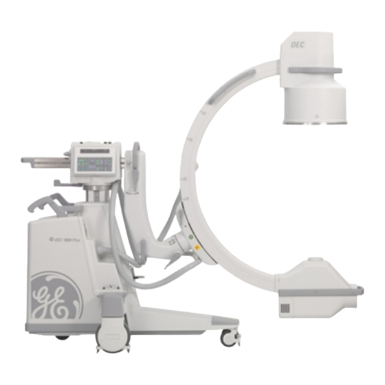
OEC 9800 Installation Procedure
Overview.........................................................................................................................................................................3
Unpacking the System ..................................................................................................................................................3
Depalletization Performed By .......................................................................................................................................4
Installation Report .........................................................................................................................................................5
C-Arm Damage Inspection ...........................................................................................................................................5
Workstation Damage Inspection ...................................................................................................................................5
Inventory of Customer Items.........................................................................................................................................6
C-Arm Items ..............................................................................................................................................................6
Workstation Items......................................................................................................................................................6
Optional Equipment ...................................................................................................................................................6
Installation Procedures .................................................................................................................................................6
Cover Removal, Internal & Cable Inspection, Partial Setup..........................................................................................7
Mechanical Checks.....................................................................................................................................................10
The Power Cord Assembly .........................................................................................................................................10
Isolation Transformer Strapping .................................................................................................................................12
Power ON System ......................................................................................................................................................16
Line Voltage Regulation..............................................................................................................................................20
C-Arm Control Panel and Foot/handswitch Check .....................................................................................................21
Workstation Keyboard Check .....................................................................................................................................24
Backup the Configuration Files...................................................................................................................................25
Options .......................................................................................................................................................................26
Cine Archive Disk Test ............................................................................................................................................26
High Capacity Disk Test ..........................................................................................................................................26
VCR Test.................................................................................................................................................................26
IR Transmitter Test..................................................................................................................................................26
Digital Hardcopy Camera test..................................................................................................................................27
Instant Film/Paper (Onboard) Printer.......................................................................................................................27
Thermal Printer Test................................................................................................................................................27
Contents
Contents
Installation
Service
Schematics
Periodic
1
Illustrated
Advertisement

Related Manuals for GE OEC 9800


Summary of Contents for GE OEC 9800
- Page 1 OEC 9800 Installation Procedure Contents Overview..................................3 Unpacking the System ..............................3 Depalletization Performed By ............................4 Installation Report .................................5 C-Arm Damage Inspection ............................5 Workstation Damage Inspection ...........................5 Inventory of Customer Items............................6 C-Arm Items ................................6 Workstation Items..............................6 Optional Equipment ..............................6 Installation Procedures ..............................6 Cover Removal, Internal &...
- Page 2 OEC 9800 Installation Procedure DICOM ..................................27 9800 FluoroTrak ..............................28 Radiographic Beam Alignment Test ...........................32 Film Exposure .................................32 50 mm x 50 mm Field Verification ...........................33 Centering.................................33 Normal Field Verification ............................33 MAG1 Field Verification............................34 MAG2 Field Verification............................34 Pass or Fail ................................35 Preparing the Pallet for Return ...........................36...
-
Page 3: Unpacking The System
OEC 9800 Installation Procedure Overview Access the latest version of the 9800 Installation Report/Checklist, 00-879060, and use it in conjunction with this document. Follow the installation procedures in the order written, and note that the sections of the procedures correspond to the same section title in the Report/Checklist. - Page 4 OEC 9800 Installation Procedure Figure 1 − − − − 9800 C-Arm and 1k x 1k Workstation Enclosures Depalletization Performed By Put a check in the appropriate box in the table in the corresponding section of the 9800 Installation Report/Checklist, 00-879060 (latest version).
-
Page 5: Installation Report
Each inspection of an assembly area should include its visible component parts and sub-assemblies; for example, inspection of the Image Intensifier should account for its cover, handles, screws, etc. C-Arm Damage Inspection Inspect the C-Arm for damages and record the information in the corresponding section of the latest version of the OEC 9800 Installation Report/Checklist. Workstation Damage Inspection Inspect the Workstation for damages and record the information in the corresponding section of the latest version of the OEC 9800 Installation Report/Checklist. -
Page 6: Installation Procedures
If no options are provided, check the No Options checkbox only. Write in any options that are present but not listed. Installation Procedures Follow these installation procedures in the order written to get the 9800 system operational, and record the information asked for in the corresponding sections of the OEC 9800 Installation Report/Checklist, 00-879060 (access the latest version). Contents Installation... - Page 7 OEC 9800 Installation Procedure Cover Removal, Internal & Cable Inspection, Partial Setup Note: Observe electrostatic discharge safety procedures. 1. Check the antistatic drag cable on the Workstation and the C-Arm. 2. Inspect the interconnect cable, AC power cable and the high voltage cable for wear, abrasion and bent or broken pins.
- Page 8 OEC 9800 Installation Procedure Figure 2 − − − − Removing the Workstation’s Covers (covers arranged for illustration purposes) Contents Installation Service Schematics Periodic Illustrated...
- Page 9 OEC 9800 Installation Procedure 6. Install the skin spacer on the C-Arm. 7. Remove the C-Arm’s covers and inspect the internal cables and PCB seating. Look for loose parts. See Figure 3. Verify the eye-bolts are removed from underneath the C-Arm’s T-base (near the wheels on each side).
-
Page 10: Mechanical Checks
OEC 9800 Installation Procedure Mechanical Checks Check the entire range of Wig-Wag movement. 2. Check the entire range of Horizontal Cross-arm movement. 3. Check the entire range of Flip-Flop/C-arm pivot. Check the entire range of C-arm orbital rotation. 5. Check the entire range of L-arm rotation (N/A on Super C). - Page 11 Figure 4 − − − − Power Cord Asm. Note: The factory has attempted to provide the proper power cable plug assembly, but due to different international requirements, the proper power plug assembly may not be furnished. If assistance is required, contact GE OEC Medical Systems, Inc. WARNING Electrical circuits inside the equipment use voltages that are capable of causing serious injury or death from electrical shock.
- Page 12 OEC 9800 Installation Procedure Isolation Transformer Strapping To match the nominal wall receptacle voltage to the input (primary) of the isolation transformer, you must select the correct tap voltage for the wires on Primary 1 (BRN, WHT/BLU) and the wires on Primary 2 (WHT/BRN, BLU).
- Page 13 OEC 9800 Installation Procedure found in the row described by voltage range 110.0 to 115.9. Connect the wires as described in that row. For Example: If the voltage measured equals 224 VAC, use Table 2 (220 – 250 VAC). The correct voltage taps would be found in the row described by voltage range 220.0 –...
- Page 14 OEC 9800 Installation Procedure Table 2 (200 – 250 VAC) If the AC line Connect Connect BRN Connect BLU Connect voltage WHT/BLU WHT/BRN wire to Primary wire to Primary determined in wire to wire to #1 terminal… #2 terminal… step 1 is...
- Page 15 OEC 9800 Installation Procedure SECONDARY 1 WHT/BLU PRIMARY 1 TAPS ARE DEPENDENT UPON INCOMING LINE VOLTAGE SECONDARY 2 PRIMARY 2 WHT/BRN Figure 7 − − − − Isolation Transformer VAC Measurement Contents Installation Service Schematics Periodic Illustrated...
-
Page 16: Power On System
OEC 9800 Installation Procedure Power ON System 1. Place the C-Arm's keyswitch in the ON position (clock-wise) and then place the Workstation's power switch in the ON position. Verify that the Workstation and C-Arm complete their software boot and initialization with no errors reported on the displays. - Page 17 OEC 9800 Installation Procedure MONITOR FANS (1 EACH SIDE) ELECTRONIC BOX FANS (1 EACH SIDE) Figure 8 − − − − Workstation Fans Contents Installation Service Schematics Periodic Illustrated...
- Page 18 OEC 9800 Installation Procedure MONITOR FILTER (1) POWER SUPPLY FAN (1) REAR WORKSTATION FAN (FILTER ON REAR COVER) Figure 9 − − − − Workstation Fans Contents Installation Service Schematics Periodic Illustrated...
- Page 19 OEC 9800 Installation Procedure POWER SUPPLY X-RAY TUBE COOLING FAN (option) HV TANK FAN Figure 10 − − − − C-Arm Fan Locations Contents Installation Service Schematics Periodic Illustrated...
- Page 20 OEC 9800 Installation Procedure 4. Verify that the X-ray tube's anode is rotating by listening for a "whirring" sound. Verify operation of the vertical column lift switches. 6. Press and hold a FAST STOP switch while verifying that vertical column operation is disabled, then release the switch and verify that X-ray generation is disabled and the message FAST STOP ACTIVATED is displayed on the C-Arm's Control Panel display.
- Page 21 OEC 9800 Installation Procedure C-Arm Control Panel and Foot/handswitch Check WARNING: Some of the following procedures produces X-rays. Take appropriate precautions. 1. Press the X-ray ON switch and verify the following Image Orientation functions: A. Image Rotation key rotates the image clockwise and counter-clockwise.
- Page 22 OEC 9800 Installation Procedure 7. Press each of the following collimator switches while pressing the X-Ray ON switch and verify each of the following collimator functions again. A. Collimator iris opens/closes B. Collimator semitransparent leaves open and close C. Collimator semitransparent leaves rotate 8.
- Page 23 OEC 9800 Installation Procedure B. Verify that the audible tone beeps at twice the normal rate and the X-ray indicator flashes. C. Select a pulse rate of 8 PPS via the Workstation Mode screen and press the right foot/handswitch. D. Verify that the X-ray indicator flashes at approximately twice the rate as the previous step.
- Page 24 OEC 9800 Installation Procedure Workstation Keyboard Check WARNING This procedure produces X-rays. Take appropriate precautions. 1. Verify the EDGE ENHANCEMENT function displays an indicator bar and that the amount of edge enhancement can be increased and decreased. 2. Verify the NOISE FILTER function displays an indicator bar and that the amount of filtering can be increased and decreased.
- Page 25 OEC 9800 Installation Procedure Backup the Configuration Files If the Remote Utilities Tool is not installed on the Laptop, install it now. 1. Connect the RUT cable between the Serial port on your Laptop and the ARCNET connector on the Workstation.
- Page 26 OEC 9800 Installation Procedure Options Refer to the 1k x 1k Workstation or Series 9800 C-Arm Operator’s Guide for operating instructions if necessary. Check the appropriate boxes in the corresponding section of the Report/Checklist. Ignore any following sections that are non-applicable to the system.
- Page 27 OEC 9800 Installation Procedure Digital Hardcopy Camera test 1. Verify operation of the digital hardcopy camera. Refer to the Operator's Guide Supplement if necessary. Instant Film/Paper (Onboard) Printer 1. Remove the shipping pins from the printers front ventilation grill. There are two pins connected with tape which secure the thermal printhead.
- Page 28 OEC 9800 Installation Procedure 3. Verify images can be archived and printed via the DICOM interface. 4. Verify that scheduled exams can be downloaded via the DICOM interface. 9800 FluoroTrak 1. If the FluoroTrak option is installed, verify that the FluoroTrak application software booted successfully and no error messages are visible on the Flat Panel Display (FPD).
- Page 29 OEC 9800 Installation Procedure Install the Calibration Fixture on the Image Intensifier. IMAGE INTENSIFIER CALIBRATION FIXTURE Figure 12. Calibration Unit Mounted on Image Intensifier Contents Installation Service Schematics Periodic Illustrated...
- Page 30 OEC 9800 Installation Procedure 4. Position the C-arm so the II is closest to the floor. Complete a calibration by performing the following. Connect the Transmitter, and both receivers (Probe and Calibration Fixture) to the panel located on the left side of the Workstation.
- Page 31 OEC 9800 Installation Procedure 6. Verify tracking by performing the following. A. Place the tip of the Probe in the dimple located on the Transmitter. B. Select the VERIFY button on the Visualization menu. Note: The screen changes to the Visualization Option menu.
- Page 32 The Radiographic Beam Alignment Test requires the exposure and development of a film. If a film processor is not located on site, is not functional, or is unavailable, it will not be possible to perform this test. GE OEC may follow up with the customer to verify any reasons listed for not performing the Radiographic Beam Alignment Test.
- Page 33 OEC 9800 Installation Procedure Select Manual - Fluoro, MAG 2 field and then Film mode. Take a 55 KVp @ 1.5 mAs exposure. Select Manual - Fluoro and completely close the collimator iris. Select Film mode. Take a 55 KVp @ 1.5 mAs exposure.
- Page 34 OEC 9800 Installation Procedure Calculate and record the absolute value of the difference between the film and Workstation X axis values (X – X Film Fluoro ). Verify that the difference recorded is less than 28 mm (3% SID). Diff 4.
- Page 35 OEC 9800 Installation Procedure Make a MAG2 mode Fluoro exposure. Using the scale on the beam alignment tool, measure and record the X and Y diameters and Y ) displayed within the digital mask on the Workstation. Fluoro Fluoro Calculate and record the absolute value of the difference between the film and Workstation X axis values (X –...
- Page 36 1. Place all hardware removed from the C-Arm pallet such as turnbuckles, eyebolts, spacers, and guide wires, in a cardboard box or plastic bag and return the box and the pallet to GE OEC Medical Systems, Inc. Discard the C-Arm stabilizing brace and the cross-arm shipping block.
- Page 37 OEC 9800 Installation Procedure Reporting for International Systems • Distribute the Report/Checklist, as outlined in Field Service Procedure No. FSP-10. Installation Comments Write any comments important to the installation in the corresponding section of the Report/Checklist. Contents Installation Service Schematics...
Need help?
Do you have a question about the OEC 9800 and is the answer not in the manual?
Questions and answers