Sign In
Upload
Manuals
Brands
Carrier Manuals
Refrigerator
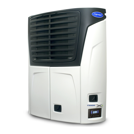
Transicold X4 7300
Carrier Transicold X4 7300 Manuals
Manuals and User Guides for Carrier Transicold X4 7300. We have
5
Carrier Transicold X4 7300 manuals available for free PDF download: Operation & Service Manual, Operator's Manual, User Manual
Carrier X4 7300/7500 Trailer & Rail Refrigeration Units Manual
Brand:
Carrier
| Category:
Refrigerator
| Size: 0 MB
Table of Contents
INTRODUCTION
Unit Identification
SAFETY
AUTO-START
COOLING SYSTEM
REFRIGERANT
BATTERY
STARTING UNIT
INSPECT MODE
STOPPING UNIT
EMERGENCY BYPASS MODE
PRETRIP INSPECTION
GENERAL TROUBLESHOOTING
General Troubleshooting
Unit won't crank.
Unit won't start.
Unit won't run.
Unit stops operating.
Unit not cooling/heating properly.
PRIMING FUEL SYSTEM
EMERGENCY ROAD SERVICE
Documents / Resources
References
Advertisement
Carrier Transicold X4 7300 Operation & Service Manual (282 pages)
Trailer and Rail Refrigeration Units
Brand:
Carrier
| Category:
Utility Vehicle
| Size: 21 MB
Table of Contents
Operation & Service Manual X4 7300 & X4 7500
3
Table of Contents
3
List of Illustrations
12
Safety Precautions
15
Safety Precautions Specific Warning, Caution, and Notice Statements
15
Safety Decals
21
Figure 2.4 Power Train
25
Figure 2.9 Light Bar
25
General Description
26
Introduction
26
Table 2-1 Model Chart
26
Table 2-2 Additional Support Manuals
26
Unit Description
26
Figure 2.1 Front View - Refrigeration System Components
27
Engine
28
Engine Coolant Temperature Sensor (ENCT)
28
Engine Speed Sensor (ENSSN)
28
Figure 2.2 Front View - Engine, Control System & Autofresh Components
28
Defrost Termination Temperature Sensor (DTT)
29
Evaporator Outlet Pressure Transducer (EVOP)
29
Evaporator Outlet Temperature Sensor (EVOT)
29
Figure 2.3 Evaporator Section - Grille Removed
29
Return Air Temperature Sensor (RAT)
29
Supply Air Temperature Sensor (SAT)
29
Alternator
31
Alternator Operation
31
Compressor
31
Major Working Parts
31
Power Train
31
Unloaders
31
Voltage Regulator Operation
31
Figure 2.5 Compressor Cylinder Head Unloaded
32
Unloaded Operation
32
Compressor Discharge Pressure Transducer (CDP)
33
Compressor Discharge Temperature Sensor (CDT)
33
Compressor Suction Pressure Transducer (CSP)
33
Compressor Suction Temperature Sensor (CST)
33
Compressor Switches, Transducers and Sensors
33
Figure 2.6 Compressor Cylinder Head Loaded
33
High Pressure Switch (HPS)
33
Loaded Operation
33
Ambient Air Temperature Sensor (AAT)
34
Condenser Coil
34
Evaporator Coil
34
Evaporator Expansion Valve (EVXV)
34
Evaporator Section
34
Filter-Drier
34
Heat Exchanger
34
Receiver
34
Solenoid Valves
34
Automatic Start-Stop
35
Component Description and Location
35
Multiple Languages
35
Special Features
35
System Operating Controls and Components
35
Figure 2.7 Power Control Module
36
Main Microprocessor Module
36
Microprocessor Status LED
36
Power Control Module
36
SVM Module
36
Display Module (DM)
37
Engine Control Unit (ENCU)
37
Figure 2.8 Display Module
37
Display Module Keys
38
Light Bar
38
Options
38
Remote Switch(Es)
38
Electric Fuel Pump
39
Fuel Heater
39
Fuel Level Sensor
39
Remote Panel
39
Remote Temperature Sensors
39
Compressor Data
40
Engine Data
40
2.10 Component Resistance & Current Draw
41
2.11 Safety Devices
41
Refrigeration System Data
41
Refrigeration Circuit During Cooling
42
Figure 2.10 Refrigeration Circuit Cooling
43
Figure 2.11 Refrigeration Circuit - Heat and Defrost
44
Section 3 - Operation
45
Display
46
Operation
46
Display Screens
47
Intelliset
48
Starting
48
Pretrip
50
Changing Setpoint
53
Start-Stop Operation
54
Continuous Operation
55
Data Recorder
55
Control System Information
56
Data Downloading
56
Data Recording
56
Datalink Data Recorder Power-Up
56
3.10 Manual Defrost
58
3.11 Language Selection
59
3.12 Advanced User
60
3.13 Unit Data
61
Table 3-1 Unit Data
62
3.14 View Active Alarms
63
3.15 View Hour Meters
64
3.16 Functional Parameters
64
Table 3-2 Functional Parameters
65
3.17 Sleep Mode
68
3.18 Stopping Unit
70
3.19 OPTION - Datatrak
70
3.20 Remote Panel
71
Section 4 - Engine and Temperature Control
73
Engine Control
74
Engine Start-Up Sequence
74
Introduction
74
Sequence of Operation - Electrical
74
Figure 4.1 Auto Start Sequence
75
Table 4-1 Engine Preheat Time
75
Transition to High Speed
75
Cooling
76
Heating
76
Modes of Operation
76
Pull Down/Pull-Up
76
Cool Pulsed Mode
77
Defrost
77
Heat Pulsed Mode
77
Null Pulsed Mode
77
Overrides
77
Ultrafresh 3 CSMV/EVXV Control
77
Perishable and Frozen Setpoint Ranges
78
Start-Stop Configuration
78
Start-Stop Operation
78
Stop Parameters
78
Temperature Control
78
Temperature Determination
78
Re-Start Parameters
79
Continuous Operation
80
Figure 4.2 Start-Stop Default Operating Sequence
80
Start-Stop Operating Sequence
80
Autofresh Air Exchange
81
Figure 4.3 Continuous Default Operating Sequence
81
Table 4-2 Continuous Operation Modes
81
Defrost
82
Defrost Initiation and Start
82
Normal Defrost Operation (Ambient Air Temperature Less than 80°F (26.7°C)
82
Normal Defrost Termination
82
Normal Defrost Termination Sequence
82
4.10 User Selected Override Operation
83
Freshprotecttm Supply Air Control
83
High Ambient Defrost Operation
83
Temperature Range Lock 1 & 2
83
Figure 4.4 Range Lock Settings - Non Overlapping
84
Figure 4.5 Range Lock Settings - Overlapping
84
Productshield
85
Air Flow
87
Cargo Protect Mode
87
Engine Speed Overrides
87
Preprogrammed Software Overrides
87
Unloader Control Overrides
88
CSMV Control Overrides
89
Section 5 - Control System Interface
90
Figure 5.3 Inactive Alarms
90
Figure 5.5 Component Test Mode
90
Figure 5.7 PC Mode
90
Figure 5.1 Technician Mode
91
Interface Methods
91
Section 5 - Control System Interface
91
Technician Mode
91
Figure 5.2 Technician Hour Meters
92
Technician Hour Meters
92
Inactive Alarms
93
Configuration Settings
94
Figure 5.4 Setting Configurations
94
Service Mode
97
Data Transfer USB Memory Device
98
Figure 5.6 Creating a Data Transfer USB Memory Device
98
Usb Memory Devices
98
Downloading Data Files
100
Figure 5.8 Downloading Data Files
100
Figure 5.9 Installing Software
101
Installing Software
101
Figure 5.10 Transferring Configuration Files
102
Transferring Configuration Files
102
TRU-Tech
103
Tru-Tech & Tru-View
103
TRU-View
103
Connecting Computer and Control System
104
Figure 5.11 TRU-Tech/Tru-View Connection
104
Main Microprocessor Replacement
104
Main Microprocessor Replacement
105
Main Microprocessor Setup
105
Pre-Replacement Steps
105
Configurations Via Display Mounted Keys
106
Datalink Data Recorder Via TRU-Tech
106
Functional Parameters Via Display Mounted Keys
106
System Final Checkout
107
Table 5-1 Configuration Settings
107
Table 6-1 Messagecenter Messages
120
Section 7 - Alarm Troubleshooting
124
Introduction
127
Section 7 - Alarm Troubleshooting
127
Notes
128
00001 Low Fuel Level Warning
129
Alarms
129
00011 Low Engine Oil Pressure
130
00012 High Coolant Temperature
131
00013 High Discharge Pressure
133
00015 Battery Voltage too High
134
00016 Battery Voltage too Low
134
00017 High Comp Discharge Temp
135
00018 Low Refrigerant Pressure
136
00019 Low Fuel Shutdown
137
00020 Maximum Compressor Alarms
137
00021 Technician Reset Required
138
00022 Low Suction Superheat
138
00027 High Suction Pressure
139
00028 Check Refrigeration System
140
00030 Failed to Run Minimum Time
141
Check Heat Cycle
141
00031 Failed to Start - Auto Mode
142
00034 Engine Failed to Stop
143
00035 Check Starter Circuit
144
00036 Check Coolant Temperature
145
00037 Check Low Speed Rpm
145
00038 Check High Speed Rpm
146
Check Engine Rpm
147
00040 Check Engine Preheat Circuit
148
Engine Stalled
149
00051 Alternator Not Charging
151
00053 Box Temp Out-Of-Range
152
00054 Defrost Not Complete
154
00055 Check Defrost Air Switch
155
00056 Check Evaporator Air Flow
156
00057 Check Remote Switch 1 (Rems1)
157
00059 DATALOGGER (Datalink Data Recorder) NOT RECORDING
158
00060 DATALOGGER (Datalink Data Recorder) TIME WRONG
158
00061 Door Open (Ds1)
159
00067 Sensor 1 Input Voltage Low
160
00072 Check Encu Power Circuit
160
Check Sv1 Circuit
160
00080 Check Clutch Circuit
161
Check Sv4 Circuit
161
Check Fhr Circuit
162
Check Remote Alarm Light
162
Check Starter Solenoid Circuit
162
00085 Check Ul1 Circuit
163
00086 Check Ul2 Circuit
164
00090 Chk Afa Solenoid Circuit
165
00093 Check Startup Buzzer
166
00097 Check Sv2 Circuit
167
00121 Check Ambient Air Sensor
167
00122 Check Return Air Sensor
168
00123 Check Supply Air Sensor
168
00125 Check Comp Discharge Sensor
169
00126 Check Fuel Sensor Circuit
169
00127 Check Suction Temp Sensor
170
00129 Check Eng Coolant Sensor
170
00130 Check Engine Rpm Sensor
171
00131 Check Evap Temp Sensor
172
00132 Check Defrost Term 2 Sensor
173
00133 Check Remote Temp Sensor 1
174
00134 Check Remote Temp Sensor 2
174
P00141 Pretrip Stopped by User
175
P00143 Check Clutch Circuit
175
P00144 Check Ul1 Circuit
176
P00148 Check Sv1 Circuit
176
P00150 Check Sv4 Circuit
176
P00151 CHECK GLOW CIRCUIT (this Applies to the Engine Preheater = EPH)
176
P00152 Check Fuel Solenoid Circuit
177
P00153 Check Return Air Sensor
177
P00154 Check Supply Air Sensor
177
P00155 Check Coolant Temp Sensor
178
P00157 Check Battery Current
178
P00158 Check Ambient Air Sensor
179
P00160 Check Discharge Temp Sensor
179
P00161 Check Suction Temp Sensor
179
P00162 Check Afa Solenoid Circuit
180
P00164 Check Ul2 Circuit
180
P00165 Cannot Pump down
181
P00174 Check Low Speed Rpm
181
P00175 Check High Speed Rpm
182
P00177 Check Exv (Evxv) Superheat
182
P00178 Check Ul1
183
P00180 Check Suction Mod Valve
184
P00181 Check Sv4 Valve
185
P00182 Check Sv1 Valve
185
P00186 Check Evap Outlet Temp
185
P00191 Check Ul2
186
P00192 Check Sv2 Circuit
186
P00194 High Suction Pressure
187
P00196 High Discharge Pressure
188
P00198 Low Discharge Pressure
189
P00200 Check Ul1 Cylinders
190
P00201 Check Ul2 Cylinders
190
P00202 High Side Leak
191
P00203 Chk Discharge Check Valve
191
P00204 Low Suction Pressure
192
00223 Engine Maintenance Due
193
P00205 Chk Defrost Term 2 Sensor
193
00225 General Maintenance Due
194
00226 Service Soon-Pm #1 Due
194
00227 Service Soon-Pm #2 Due
195
00228 Service Soon-Pm #3 Due
195
00229 Service Soon-Pm #4 Due
196
00230 Service Soon-Pm #5 Due
196
Model # Error
197
Setpoint Error
197
00237 Function Parameters Error
198
00238 Configurations Error
199
00245 Cannot Save Setting
200
00246 Eeprom Write Failure
200
00248 Config Mode / Hp2 Error
201
00250 Loss of Communication with All Modules
201
00251 Loss of Communication with Input Board
201
00252 Loss of Communication with Output Board
201
00253 Loss of Communication with Suction Modulation Valve Module (Svm)
201
00254 Loss of Communication with Display Module
202
00255 Microprocessor Error
202
Update Software
202
03001 Engine Load Calibration
203
05012 Check Encu Power Circuit
204
05013 Check Clutch Circuit
205
05014 Check Starter Solenoid Circuit
206
05016 Check Remote Amber Light
206
Check Glow Plug Relay
207
20100 No Comm from Micro to Display
208
21100 No Comm from any Board to Main Micro
209
22100 No Comm from Micro to Inpbd1
209
22101 Sensor Input Voltage Low Inp1
210
22102 Sensor Input Voltage High Inp1
211
23100 No Comm from Micro to Outpbd1
211
25100 No Comm from Micro to Stp1
212
26100 No Comm from Micro to Encu
213
Section 8 - Service
214
Scheduled Maintenance
215
Pre-Trip Inspection
216
Table 8-1 Maintenance Schedule
216
External Surface Service
218
Figure 8.1 Automatic Fresh Air Exchange
218
Figure 8.2 Grille Insert Removal and Door Latch Maintenance
218
Figure 8.3 Surround Removal
219
Figure 8.4 Door Latch Cable Removal
219
Engine and Engine Related Systems Service
220
Figure 8.5 Fuel System Diagram
220
Figure 8.6 Fuel Bleed Components
221
Figure 8.7 Mechanical Fuel Pump
221
Figure 8.8 Electric Fuel Pump
222
Figure 8.9 Suction Side Fuel Filter
222
Figure 8.10 Fuel Level Sensor
223
Figure 8.11 Engine Oil Level
224
Figure 8.12 Oil Drain Tool
224
Figure 8.13 Engine Preheater
225
Figure 8.14 Engine Control System Components
226
Figure 8.15 Radiator Assembly
228
Figure 8.16 Water Pump/Alternator Belt
228
Figure 8.17 Engine Crankcase Breather
229
Figure 8.18 Lower Belt
229
Power Train Service
229
Figure 8.19 Upper Power Train
231
Figure 8.20 Surround
232
Figure 8.21 Upper Frame Support
232
Figure 8.22 Refrigerant System Service Equipment
235
Refrigerant System Service
235
Compressor and Unloader Service
242
Figure 8.23 Compressor
243
Figure 8.24 Cylinder Head & Valve Plate
244
Figure 8.25 Checking Suction Valve
245
Figure 8.26 Oil Pump & Bearing Head Assembly
245
Figure 8.27 Oil Pump
245
Figure 8.28 Oil Level in Sight Glass
246
Figure 8.29 Unloader Coil
247
Refrigerant System Component Service
248
Figure 8.30 Condenser/Radiator Assembly
250
Figure 8.31 Condenser Pressure Control Solenoid Valve (SV1)
251
Figure 8.32 SV-2 and
252
Compressor Suction Modulation Valve (CSMV)
253
Figure 8.33 Stepper Test Harness
253
Figure 8.34 Suction Modulation Valve (CSMV)
253
Figure 8.35 CSMV Coil
253
Figure 8.36 Evaporator Expansion Valve
254
Figure 8.37 Evaporator Expansion Valve
255
Table 8-2 EVXV Connections
255
Figure 8.38 Check Valves
256
Figure 8.39 Typical Setup for Testing Pressure Switch
256
Figure 8.40 Defrost Air Switch Test Setup
257
8.10 Electrical System Components
258
Figure 8.41 Power Control Module
258
Figure 8.42 Alternator
260
Figure 8.43 Light Bar Connections
260
Table 8-3 Sensor Resistance
261
Table 8-4 Sensor Resistance (CDT)
262
Table 8-5 Temperature Pressure Chart
263
Carrier Transicold X4 7300 Operation & Service Manual (277 pages)
Trailer and Rail Refrigeration Units
Brand:
Carrier
| Category:
Refrigerator
| Size: 3 MB
Table of Contents
− Continued
8
Table of Contents
8
List of Illustrations
14
Section 1 − Safety Precautions
17
Specific Warning and Caution Statements
18
General Description
27
Table 2-1 Model Chart
27
Table 2-2 Additional Support Manuals
27
Unit Description
27
Figure 2−1 Front View - Refrigeration System Components
28
Figure 2−2 Front View - Engine, Control System & Autofresh Components
29
Figure 2−3 Evaporator Section - Grille Removed
30
Condensing Section
31
Figure 2−4 Power Train
32
Figure 2−5 Compressor Cylinder Head Unloaded
33
Figure 2−6 Compressor Cylinder Head Loaded
34
Evaporator Section
35
System Operating Controls and Components
36
Figure 2−7 Power Control Module
37
Figure 2−8 Display Module
38
Figure 2−9 Light Bar
39
Engine Data
40
Compressor Data
40
Refrigeration System Data
41
Safety Devices
41
Refrigerant Circuit During Cooling
42
Figure 2−10 Refrigerant Circuit - Cooling
43
Figure 2−11 Refrigerant Circuit - Heat & Defrost
44
Section 3 Operation
46
Lcd Display Screens
47
Default Screen
47
Typical Menu Screen
47
Changing Setpoint
54
Start-Stop Operation
55
Continuous Operation
56
Data Recorder
57
Manual Defrost
59
Language Selection
60
Advanced User
61
Table 3-1 Unit Data
63
View Active Alarms
64
Table 3-2 Functional Parameters
66
Start-Stop Settings
68
Viewing Preferences
69
Sleep Mode
69
Stopping Unit
71
Engine Control
73
Figure 4−1 Auto Start Sequence
74
Table 4−1 Engine Preheat Time
74
Modes of Operation
75
Temperature Control
77
Figure 4−2 Start-Stop Default Operating Sequence
79
Figure 4−3 Continuous Default Operating Sequence
80
Table 4−2 Continuous Operation Modes
80
Figure 4−4 Range Lock Settings - Non Overlapping
83
Figure 4−5 Range Lock Settings - Overlapping
83
Interface Methods
90
Section 5 Control System Interface
90
Technician Mode
90
Figure 5−2 Technician Hour Meters
91
Figure 5−3 Inactive Alarms
92
Figure 5−4 Setting Configurations
93
Figure 5−4 Setting Configurations - Continued
94
Figure 5−5 Component Test Mode
95
Usb Memory Devices
97
Figure 5−6 Creating a Data Transfer USB Memory Device
97
Figure 5−7 PC Mode
98
Figure 5−8 Downloading Data Files
99
Figure 5−9 Installing Software
100
Figure 5−10 Transferring Configuration Files
101
Figure 5−11 TRU-Tech/Tru-View Connection
102
Unit Identification
106
Table 5−1 Configuration Settings
107
Remote Sensors
115
Section 6 − Messagecenter
120
Section 7 − Alarm Troubleshooting
125
Check Remote Alarm Light
161
Check Starter Solenoid Circuit
161
00085 Check Ul1 Circuit 7−37
162
Check Ul2 Circuit
163
Chk Afa Solenoid Circuit
164
Check Startup Buzzer
165
Check Sv2 Circuit
165
00121 Check Ambient Air Sensor 7−41
166
00122 Check Return Air Sensor 7−41
166
Check Supply Air Sensor
167
00125 Check Comp Discharge Sensor
168
00126 Check Fuel Sensor Circuit 7−43
168
Check Eng Coolant Sensor
169
Check Suction Temp Sensor
169
Check Engine Rpm Sensor
170
Check Evap Temp Sensor
171
Check Defrost Term 2 Sensor
172
Check Remote Temp Sensor 1
173
P00141 Pretrip Stopped by User 7−49
174
P00143 Check Clutch Circuit
174
P00144 Check Ul1 Circuit 7−49
174
P00148 Check Sv1 Circuit 7−50
175
P00150 Check Sv4 Circuit 7−50
175
P00151 CHECK GLOW CIRCUIT (this Applies to the Engine Preheater = EPH)
175
P00152 Check Fuel Solenoid Circuit
175
P00153 Check Return Air Sensor 7−50
175
P00154 Check Supply Air Sensor 7−51
176
P00155 Check Coolant Temp Sensor
176
P00157 Check Battery Current 7−51
176
P00158 Check Ambient Air Sensor 7−52
177
P00160 Check Discharge Temp Sensor
177
P00161 Check Suction Temp Sensor 7−52
177
P00162 Check Afa Solenoid Circuit
177
P00164 Check Ul2 Circuit 7−53
178
P00165 Cannot Pump down
178
P00174 Check Low Speed Rpm 7−54
179
P00175 Check High Speed Rpm 7−54
179
P00177 Check Exv (Evxv) Superheat 7−55
180
P00178 Check Ul1
181
P00180 Check Suction Mod Valve 7−57
182
Check Refrigerant Charge
188
Section 8 − Service
212
Figure 8−24 Compressor
213
Section Layout
213
Scheduled Maintenance
213
Pre-Trip Inspection
213
Table 8−1 Maintenance Schedule
214
Table 8−2 Pre-Trip Inspection
215
Before Starting Engine
215
Figure 8−1 Automatic Fresh Air Exchange
217
Figure 8−2 Grille Insert Removal and Door Latch Maintenance
217
Mounting Bolts
218
Figure 8−3 Surround Removal
218
Figure 8−4 Door Latch Cable Removal
218
Figure 8−5 Fuel System Diagram
219
Figure 8−6 Fuel Bleed Components
219
Figure 8−7 Mechanical Fuel Pump
220
Figure 8−8 Electric Fuel Pump
220
Figure 8−10 Fuel Level Sensor
222
Figure 8−11 Engine Oil Level
223
Figure 8−12 Oil Drain Tool
223
Figure 8−13 Engine Preheater
224
Figure 8−14 Engine Control System Components
224
Figure 8−15 Rack Position Sensor Kit
224
Figure 8−16 Suction Mod Valve Screen
225
Figure 8−17 Engine Load Screen
225
Figure 8−18 Radiator Assembly
226
Figure 8−19 Water Pump/Alternator Belt
227
Figure 8−20 Engine Crankcase Breather
227
Figure 8−21 Lower Belt
228
Figure 8−22 Upper Power Train
229
Figure 8−23 Refrigerant System Service Equipment
232
Figure 8−25 Cylinder Head & Valve Plate
240
Figure 8−26 Checking Suction Valve
240
Figure 8−29 Unloader Coil
243
Figure 8−30 Condenser/Radiator Assembly
245
Figure 8−31 Condenser Pressure Control Solenoid Valve (SV1)
246
Figure 8−32 SV-2 and
247
Figure 8−33 Stepper Test Harness
248
Figure 8−34 Suction Modulation Valve (CSMV)
248
Figure 8−35 CSMV Coil
248
Figure 8−36 Evaporator Expansion Valve
249
Table 8−3 EVXV Connections
249
Figure 8−37 Evaporator Expansion Valve
250
Figure 8−38 Check Valves
250
Figure 8−39 Typical Setup for Testing High Pressure Switch
251
Figure 8−40 Defrost Air Switch Test Setup
252
Figure 8−41 Power Control Module
253
Figure 8−43 Light Bar Connections
254
Table 8−4 Sensor Resistance
255
Table 8−5 Sensor Resistance (CDT)
256
Table 8−6 Temperature Pressure Chart
257
Unit Troubleshooting
259
Figure 8−42 Alternator
261
Refrigeration / Temperature Control
262
Advertisement
Carrier Transicold X4 7300 Operator's Manual (196 pages)
Trailer & Rail Refrigeration Units
Brand:
Carrier
| Category:
Refrigerator
| Size: 6 MB
Table of Contents
English
5
Table of Contents
5
Introduction
7
Unit Identification
8
Safety
9
Auto-Start
9
Cooling System
9
Refrigerant
9
Battery
9
Display
10
Display Screens
11
Default Screen
11
Starting Unit
12
Intelliset
16
Operator Messages
18
Pretrip
20
Changing Setpoint
22
Start-Stop or Continuous Operation
24
Start-Stop or Continuous Operation
25
Data Recorder / Trip Start
26
Manual Defrost
28
Language Selection
30
Unit Data
31
Unit Data - Continued
32
Refrigeration System
32
Suction Pressure
33
Alarm List
34
View Hour Meters
35
Stopping Unit
36
Emergency Bypass Mode
37
Pre-Trip Inspection
38
Product Loading
40
Before Loading
40
Recommended Transport Temperatures
41
General Troubleshooting
42
Fuses
44
Maintenance
46
Maintenance Schedule
46
Operation
47
Priming Fuel System
49
Emergency Road Service
50
Français
53
Introduction
55
Identification de L'unité
56
Batterie
57
Démarrage Automatique
57
Fluide Frigorigène
57
Système de Refroidissement
57
Sécurité
57
Affichage
58
Écrans D'affichage
59
Écran Par Défaut
59
Mise en Marche de L'unité
60
Mode D'inspection
62
Intelliset
64
Messages à L'intention de L'utilisateur
66
Ensemble D'essais de Mise en Marche
68
Modification du Point de Consigne
70
Marche/Arrêt ou Fonctionnement Continu
72
Enregistreur de Données / Début de Voyage
74
Dégivrage Manuel
76
Sélection de la Langue
78
Données de L'unité
79
Suction Pressure
81
Liste des Alarmes
82
Affichage des Compteurs D'heures
83
Arrêt de L'unité
84
Mode de Contournement D'urgence
85
Vérification Avant Départ
86
Chargement des Produits
88
Températures de Transport Recommandées
89
Dépannage Général
90
Fusibles
92
Calendrier D'entretien
94
Entretien
94
En Carburant
97
Service Routier D'urgence
98
Português
101
Introdução
103
Identificação da Unidade
104
Bateria
105
Partida Automática
105
Refrigerante
105
Segurança
105
Sistema de Resfriamento
105
Painel
106
Telas Do Painel
107
Partida da Unidade
108
Modo de Inspeção
110
Intelliset
112
Mensagens Ao Operador
114
Pretrip
116
Alteração Do Ponto de Ajuste
118
Operação de Partida/Parada ou Contínua
120
Registro de Dados / Início da Viagem
122
Degelo Manual
124
Seleção Do Idioma
126
Dados da Unidade
127
Fuel Level
129
Suction Pressure
129
Lista de Alarmes
130
Visualizar Horímetros
131
Parada da Unidade
132
Modo Alternativo de Emergência
133
Inspeção Pré-Viagem
134
Carregamento Do Produto
136
Temperaturas Recomendadas para Transporte
137
Resolução de Problemas Gerais
138
Fusíveis
140
Cronograma de Manutenção
142
Manutenção
142
Escorva Do Sistema de Combustível
145
Serviço de Emergência Em Trânsito
146
Manual del Operador
147
Español
149
Introducción
151
Identificación de la Unidad
152
Autoarranque
153
Batería
153
Refrigerante
153
Seguridad
153
Sistema de Enfriamiento
153
Visualización
154
Pantallas de Visualización
155
Pantalla Inicial
155
Arranque de la Unidad
156
Modo de Inspección
158
Intelliset
160
Mensajes del Operador
162
Previaje
164
Cambiar Punto de Referencia
166
Arranque-Parada U Operación Continua
168
Registrador de Datos / Inicio de Viaje
170
Descongelamiento Manual
172
Selección de Idioma
174
Language [Idioma]
174
Datos de la Unidad
175
Sistema de Refrigeración
176
Lista de Alarmas
178
Ver Contadores Horarios
179
Parada de la Unidad
180
Modo de Bypass de Emergencia
181
Inspección de Previaje
182
Antes de Arrancar el Motor
182
Carga del Producto
184
Durante la Carga
184
Temperaturas de Transporte Recomendadas
185
Solución de Problemas Generales
186
Fusibles
188
Mantenimiento
190
Programa de Mantenimiento
190
Operación
191
Del Sistema
191
Cebado del Sistema de Combustible
193
Servicio Carretero de Emergencia
194
Carrier Transicold X4 7300 Operator's Manual (198 pages)
Trailer and Rail Refrigeration Units
Brand:
Carrier
| Category:
Refrigerator
| Size: 4 MB
Table of Contents
English
5
Table of Contents
5
Introduction
7
Unit Identification
8
Safety
9
Display
11
Starting Unit
13
Inspect Mode
15
Intelliset
17
Operator Messages
19
Pretrip
21
Changing Setpoint
24
Start/Stop or Continuous Operation
25
Data Recorder / Trip Start
27
Language Selection
31
Unit Data
32
Alarm List
35
View Hour Meters
36
Stopping Unit
37
Emergency Bypass Mode
38
Pretrip Inspection
40
Product Loading
42
General Troubleshooting
44
Fuses
46
Unit Maintenance
47
Warranty
51
Emergency Road Service
52
Français
55
Introduction
57
Identification de L'unité
58
Sécurité
59
Affichage
60
Écrans de Visualisation
61
Mise en Marche de L'unité
62
Mode D'inspection
64
Intelliset MC
66
Messages à L'intention de L'utilisateur
68
Pretrip (Vérification Avant Départ)
70
Modification du Point de Consigne
73
Marche/Arrêt ou Fonctionnement Continu
74
Enregistreur de Données/Début de Voyage
76
Dégivrage Manuel
78
Sélection de la Langue
80
Unit Data (Données de L'unité)
81
Liste des Alarmes
84
Affichage des Compteurs D'heures
85
Arrêt de L'unité
86
Mode de Contournement D'urgence
87
Vérification Avant Départ
88
Chargement des Produits
90
Températures de Transport Recommandées
91
Dépannage Général
92
Fusibles
94
Calendrier D'entretien
95
Entretien
97
Amorçage du Système D'alimentation en Carburant
98
Service Routier D'urgence
99
Español
103
Introducción
105
Identificación de la Unidad
106
Seguridad
107
Display
108
Pantallas del Display
109
Arranque de la Unidad
110
Modo Inspección
112
Intelliset TM
114
Mensajes del Operador
116
Previaje
119
Cambio del Setpoint
121
Arranque-Parada U Operación Continua
122
Grabadora de Datos / Inicio de Viaje
124
Deshielo Manual
126
Selección de Idioma
128
Datos de la Unidad
129
Lista de Alarmas
132
Ver Horómetros
133
Apagado de la Unidad
134
Modo Bypass de Emergencia
135
Inspección de Previaje
136
Carga del Producto
138
Temperaturas de Transporte Recomendadas
139
Resolución de Problemas Generales
140
Fusibles
142
Programa de Mantenimiento
143
Mantenimiento
145
Cebado del Sistema de Combustible
146
Servicio de Emergencia en Ruta
147
Português
151
Introdução
153
Identificação Do Equipamento
154
Segurança
155
Mostrador
156
Telas Do Mostrador
157
Partida Do Equipamento
158
Modo de Inspeção
160
Intelliset TM
162
Mensagens Ao Operador
164
Pré-Viagem
166
Alteração Do Ponto de Ajuste
169
Operação de Partida/Parada ou Contínuo
170
Registrador de Dados/Início da Viagem
172
Degelo Manual
174
Seleção Do Idioma
176
Dados da Unidade
177
Lista de Alarmes
180
Visualização de Horímetros
181
Desligando O Equipamento
182
Modo de Desvio de Emergência
183
Inspeção Pretrip (Pré-Viagem)
184
Carregamento Do Produto
186
Temperaturas Recomendadas para Transporte
187
Resolução de Problemas Gerais
188
Fusíveis
190
Cronograma de Manutenção
191
Manutenção
193
Sangria Do Sistema de Combustível
194
Serviço de Emergência Em Trânsito
195
Advertisement
Related Products
Carrier Transicold X4 7500
Carrier XtendFRESH
Carrier XARIOS X150-04
Carrier XARIOS X 350-05
Carrier XARIOS X 200-04
Carrier XARIOS X 300-05
Carrier XARIOS X 600
Carrier XARIOS X 500-04
Carrier Transicold Vector Multi-Temp
Carrier Transicold Vector
Carrier Categories
Air Conditioner
Heat Pump
Furnace
Chiller
Thermostat
More Carrier Manuals
Login
Sign In
OR
Sign in with Facebook
Sign in with Google
Upload manual
Upload from disk
Upload from URL