Table of Contents
Advertisement
Quick Links
Specifications
Voltage: 10-36V ACDC.
Current draw standby: Radio Awake state 16 m/a – Radio Sleep state 4.5 m/a.
Frequency: 433.39 MHz.
Remote storage: 200 remotes / 4 x e-Loops / 4 x Keypads / 4 x Entry Buttons.
Remote storage allocation: Each remote can be set to a unit number ID.
Relay: 1-amp contact rating, COM and N/O connections x 2 relays (Pulse, Latch
and Hold modes).
e-Loop: Connect direct to e-Loop to alter settings.
Lock out function: Ability to lock certain coded devices by remote 1.
Coding device
To code device: Rotate dial clockwise to CODE DEVICE then press PB (remote Push Button).
CODE LEARN will display and green LED will flash indicating coding sequence.
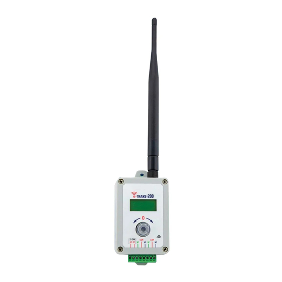
Screen Display in
operational mode>
To code remote handset:
Press remote button once > display will show ACCEPT REM 1, then screen will display CONFIRM REM 1.
Press remote button again and screen will display REM 1 CODED.
You can then follow on with a second remote in which ACCEPT REM 2 will display. If no further remote
buttons are pressed, CODE DEVICE will exit back to main screen after 5 seconds.
To code e-Loop – first option:
Rotate dial to CODE DEVICE then hold e-Loop next to the Transceiver antenna. Now press PB
and release. Display will show E-LOOP CODED. CODE DEVICE will exit and return to main screen.
To code e-Loop – second option:
Rotate dial to CODE DEVICE then press PB, CODE LEARN will be displayed. Now press and release
e-Loop CODE button. Screen will display E-LOOP CODED and will exit back to main screen,
(for commercial e-Loop, use the magnet provided to activate the CODE button)
E. sales@aesglobalonline.com
T: +44 (0) 288 639 0 693
www.aesglobalonline.com
.
Advertisement
Table of Contents

Related Manuals for AES e-TRANS-200


Summary of Contents for AES e-TRANS-200
- Page 1 Specifications Voltage: 10-36V ACDC. Current draw standby: Radio Awake state 16 m/a – Radio Sleep state 4.5 m/a. Frequency: 433.39 MHz. Remote storage: 200 remotes / 4 x e-Loops / 4 x Keypads / 4 x Entry Buttons. Remote storage allocation: Each remote can be set to a unit number ID. Relay: 1-amp contact rating, COM and N/O connections x 2 relays (Pulse, Latch and Hold modes).
- Page 2 Menu options To enter MENU options, rotate to ENTER MENU then press PB Main menu selection 1. CODED DEVICES Press PB to enter sub menu / rotate dial to select options / press PB to confirm or exit options. Sub menu options: 2.
- Page 3 1. CODED DEVICES sub menu ALLOCATION options menu (This menu allows you to set a device to Relay 1 or Relay 2) ALLOCATE BUTTON: Press to enter, screen will display RELAY 1 / BUTTON 1. Press PB to enter selection, rotate dial to change button number, press dial to confirm and move to. RELAY 2 / BUTTON 2. Press PB to enter selection or rotate dial to move to ALLOCATE LOOP.
- Page 4 SET ID Setting REMOTE ID: Press PB to enter, screen will display REM 1 / No ID. Press PB again to enter selection, rotate dial right to select UNIT 1 – UNIT 200, rotate left to select SPARE. Press PB to confirm and screen will now display REM 2 / No ID. Follow the same procedure to change, or rotate left to EXIT MENU, then press PB to exit back to sub menu.
- Page 5 (MAIN MENU) 2. RELAY FUNCTION sub menu RELAY FUNCTION (Options in this menu allow you to set relay to pulse, hold, or latch, and to set pulse time) Setting RELAY FUNTION: Press PB to enter, screen will display RELAY 1 / PULSE. Press PB again to enter selection, rotate dial right to select LATCH or HOLD.
- Page 6 Setting e-LOOP cont. (DIAGNOSTIC MENU): READING / 85 > rotate to TRIP LVL / 1000 > rotate to MOVEMENT / 0 > rotate to TEMP / 23 > rotate to EXIT/ MENU, press PB to exit. (NOTE: To set e–Loop into diagnostic mode, place magnet on the Mode recess. Both Yellow LEDs will flash.
- Page 7 (MAIN MENU) 4. RADIO SETTINGS sub menu RADIO SETTINGS (This allows you to set the receiver to sleep function mode to reduce standby current) (MAIN MENU) 5. TEST MODE sub menu TEST MODE (This allows you to test signal strength or to check background interference as well as testing each relay activation) TEST MODE: Press PB to enter, screen will display TEST SIG in top line.
Need help?
Do you have a question about the e-TRANS-200 and is the answer not in the manual?
Questions and answers