Table of Contents
Advertisement
Quick Links
Advertisement
Table of Contents

Subscribe to Our Youtube Channel
Related Manuals for Nordic Semiconductor nRF52 DK


Summary of Contents for Nordic Semiconductor nRF52 DK
- Page 1 DK Hardware v2.x.x User Guide 4397_500 / 2022-10-19...
-
Page 2: Table Of Contents
Contents Revision history ........Introduction ........Kit content . -
Page 3: Revision History
25 • Preparing the DK on page 25 • NFC antenna interface February 2017 • Created PDF for nRF52 DK v1.1.x (valid for all DK versions) • Added on page 8 • Updated: • Interface MCU firmware on page 7 •... -
Page 4: Introduction
The nRF52 Development Kit (DK) is a hardware development platform used to design and develop application firmware on the nRF52832, nRF52810, or nRF52805 System on Chip (SoC)s. To set up the nRF52 DK, see Getting started with the nRF52 DK. To start developing your application, see Software development Getting Started Guides. -
Page 5: Kit Content
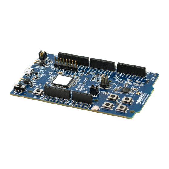
Kit content The nRF52 DK includes hardware, preprogrammed firmware, documentation, hardware schematics, and layout files. The nRF52 DK (PCA10040) comes with a Near Field Communication (NFC) antenna. Figure 1: nRF52 DK (PCA10040) and NFC antenna Hardware files The hardware design files including schematics, Printed Circuit Board (PCB) layout files, bill of materials,... -
Page 6: Interface Mcu
Interface MCU The interface MCU on the nRF52 DK runs SEGGER J-Link OB or Mbed OB interface firmware and is used to program and debug the firmware of the nRF52832 SoC. Figure 2: Interface MCU 3.1 IF Boot/Reset button The nRF52 DK has an IF Boot/Reset button (SW5). -
Page 7: Dynamic Hwfc Handling
Interface MCU The following table shows an overview of the UART connections on the nRF52832 SoC and the interface MCU. GPIO nRF52832 nRF52832 UART Interface MCU UART P0.05 P0.06 P0.07 P0.08 Table 1: Relationship of UART connections on nRF52832 and interface MCU The UART signals are routed directly to the interface MCU. -
Page 8: Msd
Interface MCU Note: When in bootloader mode, do not drag and drop any files except those downloaded from www.nordicsemi.com for use with the interface MCU. If a wrong file is used, it can overwrite the bootloader and ruin the interface MCU firmware without the possibility of recovery. 3.4 MSD The interface MCU features an MSD. -
Page 9: Hardware Description
Hardware description The nRF52 DK (PCA10040) features an onboard programming and debugging solution. In addition to radio communication, the SoC can communicate with a computer through Universal Serial Bus (USB) and a virtual COM port provided by the interface MCU. -
Page 10: Block Diagram
IF Boot/Reset 32.768 kHz 32 MHz Figure 5: Block diagram 4.3 Power supply The nRF52 DK has three power options: USB (5 V), external power supply (1.7–3.6 V), and coin cell battery. Figure 6: Power supply options (front) 4397_500... - Page 11 Hardware description Figure 7: Power supply options (back) The 5 V from the USB is regulated down to 3.3 V through an onboard voltage regulator. The battery and external power supply are not regulated. The power from the regulator and external supply is routed through diodes for reverse voltage protection (D1 and D7), where the circuit is supplied from the source with the highest voltage.
-
Page 12: Connector Interface
Note: Connect only one power source at the time. Shorting the solder bridges removes the reverse voltage protection. 4.4 Connector interface Access to the nRF52832 General-Purpose Input/Output (GPIO)s is available from connectors P2, P3, P4, P5, and P6. The P1 connector provides access to ground and power on the nRF52 DK. 4397_500... - Page 13 Some of the signals are also available on connectors P7, P8, P9, P10, P11, and P12, located on the back side of the DK. By mounting pin lists on the connector footprints, the nRF52 DK can be used as a shield for 3.3 V Arduino motherboards or other boards that follow the Arduino standard.
-
Page 14: Buttons And Leds
Hardware description Figure 11: Arduino signals routing on the nRF52 DK 4.5 Buttons and LEDs The four buttons and four LEDs on the nRF52 DK are connected to dedicated GPIOs on the nRF52832 SoC. Part GPIO Short Button 1 P0.13 Button 2 P0.14... -
Page 15: I/O Expander For Buttons And Leds
Figure 13: Button and LED configuration 4.5.1 I/O expander for buttons and LEDs The onboard GPIOs for the buttons and LEDs can conflict with boards that follow the Arduino standard. Therefore, the nRF52 DK has an I/O expander to avoid such conflicts. 4397_500... - Page 16 LED 4 Table 4: GPIO connection The I/O expander releases these GPIOs for general use when the nRF52 DK is used together with boards that follows the Arduino standard. The I/O expander can be permanently enabled by shorting solder bridge SB18, or permanently disabled by cutting the shorting track on SB19. You must also short SB18 when cutting SB19 for full compatibility with the Arduino standard.
-
Page 17: Khz Crystal
The nRF52832 SoC can use an optional 32.768 kHz crystal (X2) for higher accuracy and lower average power consumption. On the nRF52 DK, P0.00 and P0.01 are used for the 32.768 kHz crystal by default and are not available as GPIO on the connectors. -
Page 18: Debug Input
Figure 18: Debug input 4.8 Debug output The nRF52 DK supports programming and debugging external boards with nRF51 Series or nRF52 Series SoCs. To debug an external board with SEGGER J-Link OB IF, connect to the Debug out connector (P19) using a 10-pin cable. -
Page 19: Connectors For Programming External Boards
Hardware description Figure 19: Debug output connector When the external board is powered, the interface MCU detects the supply voltage of the board and programs/debugs the target chip on the external board instead of the onboard nRF52832 SoC. Note: The voltage supported by external debugging/programming is 3.0 V. You can also use P20 as a Debug out connection to program shield-mounted targets. -
Page 20: Nfc Antenna Interface
Table 7: Pinout of connector P20 for programming target on shields 4.10 NFC antenna interface The nRF52 DK supports an NFC tag. NFC-A Listen Mode operation is supported on the nRF52832 SoC. The NFC antenna input is available on connector P23 on the nRF52 DK. - Page 21 Hardware description Figure 20: NFC antenna connector NFC uses two pins, pin 11 (NFC1) and pin 12 (NFC2), to connect the antenna. These pins are shared with GPIOs (P0.09 and P0.10). The PROTECT field of the NFCPINS register in UICR defines the usage of these pins and their protection level against abnormal voltages.
-
Page 22: Solder Bridge And Test Point Overview
4.11 Solder bridge and test point overview The nRF52 DK has a range of solder bridges for enabling or disabling functionality on the DK. It also has test points available for use. Changes to these are not needed for normal use of the DK. - Page 23 This function is not recommended because it bricks your DK unless you have the tools needed to reprogram the interface MCU. Note: While this is shorted, you cannot program and debug the on-board device. The following table is a complete overview of the test points on the nRF52 DK. 4397_500...
- Page 24 Hardware description Designator Description Size Layer DHSD_P USB connector D+ 1.0 mm DHSD_N USB connector D- 1.0 mm VBUS USB voltage before power 1.0 mm switch Ground 1.0 mm IMCU_CTS UART CTS 1.0 mm IMCU_RxD UART RXD 1.0 mm IMCU_RTS UART RTS 1.0 mm IMCU_TxD...
-
Page 25: Measuring Current
Measuring current The current drawn by the nRF52832 SoC can be monitored on the nRF52 DK. Current can be measured using the following test instruments: • Power analyzer • Oscilloscope • Ampere meter • Power Profiler Kit II (PPK2) Power analyzer and PPK2 measurements are not described in this document. See the... -
Page 26: Using An Oscilloscope For Current Profile Measurement
Measuring current Figure 22: Preparing the DK for current measurements • To put P22 in series with the load, cut the PCB track shorting solder bridge SB9. • If using external power supply, short solder bridge SB12 to bypass the protection diode, which would otherwise give a voltage drop. -
Page 27: Using An Ampere Meter For Current Measurement
Measuring current Figure 23: Current measurement with an oscilloscope Some tips to reduce noise: • Use probes with 1× attenuation • Enable averaging mode to reduce random noise • Enable high resolution function if available Use a minimum of 200 kSa/s (one sample every 5 µs) to get the correct average current measurement. 5.3 Using an ampere meter for current measurement The average current drawn by the nRF52832 SoC can be measured using an ampere meter. - Page 28 Measuring current Figure 24: Current measurement with an ampere meter Note: An ampere meter measures the average current drawn by the nRF52832 SoC if: • The average timing for the ampere meter is long (for example, 1 s or more). •...
-
Page 29: Rf Measurements
RF measurements The nRF52 DK is equipped with a small coaxial connector (J1) for conducting measurements of the RF signal with a spectrum analyzer. The connector is of SWF type (Murata part no. MM8130-2600) with an internal switch. By default, when no cable is attached, the RF signal is routed to the onboard trace antenna. -
Page 30: Glossary
Glossary Clear to Send (CTS) In flow control, the receiving end is ready and telling the far end to start sending. Data Terminal Ready (DTR) A control signal in RS-232 serial communications transmitted from data terminal equipment, such as a computer, to data communications equipment. Development Kit (DK) A hardware development platform used for application development. - Page 31 In flow control, the transmitting end is ready and requesting the far end for a permission to transfer data. Root Mean Square (RMS) An RMS meter calculates the equivalent Direct Current (DC) value of an Alternating Current (AC) waveform. A true RMS meter can accurately measure both pure waves and the more complex nonsinusoidal waves.
-
Page 32: Recommended Reading
Recommended reading In addition to the information in this document, you may need to consult other documents. Nordic documentation • nRF52832 Product Specification • nRF52832 Compatibility Matrix • nRF52832 Errata 4397_500... -
Page 33: Legal Notices
Nordic Semiconductor ASA customers using or selling these products for use in such applications do so at their own risk and agree to fully indemnify Nordic Semiconductor ASA for any damages resulting from such improper use or sale.
Need help?
Do you have a question about the nRF52 DK and is the answer not in the manual?
Questions and answers