Table of Contents
Advertisement
Quick Links
Advertisement
Table of Contents

Related Manuals for Nordic Semiconductor Power Profiler Kit


Summary of Contents for Nordic Semiconductor Power Profiler Kit
- Page 1 Power Profiler Kit User Guide v1.0 Doc. ID 4425_027 v1.0 2016-10-13...
-
Page 2: Table Of Contents
Chapter 4: Installing the Power Profiler Kit software package....13 Chapter 5: Configuring the Power Profiler Kit..........14 5.1 Measurement accuracy optimization......................14 5.2 Connecting the Power Profiler Kit to the nRF5x DK..................15 5.3 Current measurements on the nRF5x DK......................15 5.4 Current measurements on the nRF5x DK while debugging..............16 5.5 Current measurements on a custom hardware with nRF5x DK............ -
Page 3: Revision History
Revision history Table 1: Revision history Date Version Description October 2016 First release Page 3 Doc. ID 4425_027 v1.0... -
Page 4: Chapter 1: Power Profiler Kit Content And Key Features
Power Profiler Kit content and key features The Power Profiler Kit (PPK) is an affordable and flexible tool to obtain real-time power consumption measurements on your designs. The PPK measures current consumption for a connected nRF5x Development Kit or any external board. It can measure current from 1 uA up to 70 mA and give a detailed picture of the current profile for the user application. - Page 5 1 Power Profiler Kit content and key features • Real-time current measurement display • Long recording display, up to 20 seconds • Real-time display, down to 15 µs resolution • Internal/external trigger • Screen data export Applications • Quick power consumption measurements on a firmware running on an nRF5x DK •...
-
Page 6: Chapter 2: Quick Start
Chapter 2 Quick start Your Power Profiler Kit (PPK) can be up and running in just a few steps. In the simplest configuration, the PPK is connected to an nRF5x Development Kit (DK), which is not included in the present package. Configure the PPK for current measurements as described in... - Page 7 2 Quick start 4. Start the PPK desktop application as described in Using the Power Profiler Kit desktop application on page You are ready to perform measurements with the PPK. For firmware upgrade, see Upgrading the firmware on page 26.
-
Page 8: Chapter 3: The Power Profiler Kit Overview
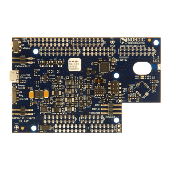
Chapter 3 The Power Profiler Kit overview The Power Profiler Kit (PPK) contains both hardware and software components. It offers a current measurement functionality through several configuration setups. The following subsections provide an overview of the measurement system and PPK components, such as connectors and switches. - Page 9 3 The Power Profiler Kit overview • DK interface • PPK on-board voltage regulator • External supply The power supply is selected by the power select switch (SW4). The PPK on-board voltage regulator is supplied by the 5 V USB power supply. Its output can be adjusted between 1.8 V and 3.6 V by the nRF52832 through the PPK desktop application.
-
Page 10: The Power Profiler Kit Connectors
3 The Power Profiler Kit overview The DUT can be turned on and off with a power switch controlled from the PPK desktop application. EEPROM On the PPK, there is an EEPROM memory connected to the nRF52832 SoC. EEPROM is used to store calibration data. -
Page 11: The Power Profiler Kit Switches
3.3 The Power Profiler Kit switches The Power Profiler Kit (PPK) has three switches that are used to select the DUT on which the measurements are performed, power supply, and SEGGER J-Link connection respectively. - Page 12 3 The Power Profiler Kit overview Switch Description DK: The measurements are performed on the nRF5x DK. • External: The measurements are performed on the external/custom hardware • connected to the External DUT (P16) connector. Power select (SW4) Used to select the power source for the PPK and DUT.
-
Page 13: Chapter 4: Installing The Power Profiler Kit Software Package
Installing the Power Profiler Kit software package This section describes the installation procedure for the Power Profiler Kit (PPK) software package. Python 2.7.12 environment, SEGGER J-Link and the nRF5x Command Line Tools for Microsoft Windows are required before the PPK software package is installed. -
Page 14: Chapter 5: Configuring The Power Profiler Kit
Chapter 5 Configuring the Power Profiler Kit This section describes four different configuration setups for the Power Profiler Kit (PPK) and methods for current measurement. To configure the PPK, complete the following steps: 1. For measurement accuracy, some adjustments are needed. For details, see... -
Page 15: Connecting The Power Profiler Kit To The Nrf5X Dk
5 Configuring the Power Profiler Kit 5.2 Connecting the Power Profiler Kit to the nRF5x DK For all of the PPK configurations, except when the PPK is running standalone, the PPK needs to be connected to the nRF5x Development Kit. -
Page 16: Current Measurements On The Nrf5X Dk While Debugging
5 Configuring the Power Profiler Kit • The USB cable is inserted into the USB on the nRF5x DK and connected to a computer with the PPK desktop application. 5.4 Current measurements on the nRF5x DK while debugging The purpose of this setup is to be used at a design and optimization stage where no custom hardware is available yet. - Page 17 5 Configuring the Power Profiler Kit The power supply is provided either by the PPK on-board regulator or an external power source. The power supply is applied to the nRF5x DK, which in turn powers the PPK board. This is used to supply power to the on-board analog measurement circuitry and the on-board regulator with 5 V.
-
Page 18: Current Measurements On A Custom Hardware Without Using An Nrf5X Dk
5 Configuring the Power Profiler Kit • The custom hardware (DUT) is connected to the External DUT (P16) connector of the PPK. • The power source is one of the following: • The PPK on-board regulator: Set the Power select (SW4) switch in the "Reg" position. - Page 19 5 Configuring the Power Profiler Kit Figure 14: Current measurements standalone with an external power source Make sure that the following are configured: • The DUT select (SW2) switch is in the "External" position. • The custom hardware (DUT) is connected to the External DUT (P16) connector of the PPK.
-
Page 20: Chapter 6: Connecting The Power Profiler Kit To A Computer
Connecting the Power Profiler Kit to a computer You need to connect the Power Profiler Kit (PPK) to a computer with a USB cable in order to use it. 1. Use a USB cable to connect the PPK to your computer. -
Page 21: Chapter 7: Using The Power Profiler Kit Desktop Application
Chapter 7 Using the Power Profiler Kit desktop application The Power Profiler Kit (PPK) must be configured correctly, connected to your computer, and powered before the desktop application can be started. To start the PPK desktop application, do the following: 1. -
Page 22: Configuration Settings
7 Using the Power Profiler Kit desktop application 7.1 Configuration settings A continuously updated calculation of average, RMS, maximum, and minimum current consumption is made during the measurement and displayed in the Settings window of the PPK desktop application. The available configuration settings in the Settings window of the PPK desktop application are: DUT On/Off Allows you to turn the power on and off for the DUT. - Page 23 7 Using the Power Profiler Kit desktop application automatically update their calculations also when a plot is stopped. This makes it easy to select the average data consumption at specific events. Change graph color Used to adjust the color of the graph (plot) displayed in the Plots window of the PPK desktop application.
-
Page 24: Options For The Plots Window
7 Using the Power Profiler Kit desktop application • Hi: 5.6 mA - 70 mA 7.2 Options for the Plots window The Plots window consists of two parts: the Average plot for longer acquisition times and the Trigger plot for high-accuracy plots of triggered events. - Page 25 7 Using the Power Profiler Kit desktop application You can also select the export format (image file, scalable vector graphics, or CSV from plot data). The Matplotlib Window option is not in use in the current version of the PPK.
-
Page 26: Chapter 8: Upgrading The Firmware
Chapter 8 Upgrading the firmware The Power Profiler Kit (PPK) firmware on the nRF52832 SoC can be upgraded in either one of two ways. Option 1 The nRF5x DK will enumerate as a mass storage device. To update the firmware of the PPK, make sure the COM switch is set in the DK position, and drag and drop the HEX file to the "JLINK"... -
Page 27: Chapter 9: Electrical Specifications
Chapter 9 Electrical specifications These specifications contain the property values that are essential for using the Power Profiler Kit (PPK). Table 5: Environmental specifications Item Name Unit Description Operating Op_Temp °C temperature Table 6: Power supply specifications Item Name Unit... - Page 28 9 Electrical specifications Item Name Unit Description Sampling rate Meas_Frequency Fixed value Page 28 Doc. ID 4425_027 v1.0...
-
Page 29: Chapter 10: Troubleshooting
Chapter 10 Troubleshooting Here are some basic troubleshooting steps to help you fix issues you may encounter when using the Power Profiler Kit (PPK). My PPK desktop application won't start Make sure the PPK board is powered and connected to the computer. Try running the desktop application from the command line as described in Using the Power... -
Page 30: Liability Disclaimer
Liability disclaimer Nordic Semiconductor ASA reserves the right to make changes without further notice to the product to improve reliability, function or design. Nordic Semiconductor ASA does not assume any liability arising out of the application or use of any product or circuits described herein. - Page 31 All rights reserved. Reproduction in whole or in part is prohibited without the prior written permission of the copyright holder.
Need help?
Do you have a question about the Power Profiler Kit and is the answer not in the manual?
Questions and answers