Table of Contents
Advertisement
Advertisement
Table of Contents

Related Manuals for Nordic Semiconductor nRF52 Preview Development Kit


Summary of Contents for Nordic Semiconductor nRF52 Preview Development Kit
- Page 1 nRF52 Preview Development User Guide v1.2 4397_497 v1.2 / 2017-02-15...
-
Page 2: Table Of Contents
Contents Revision history ........Introduction ........Setting up the development kit . -
Page 3: Revision History
Revision history Date Version Description February 2017 • Created PDF • Added on page 10 • Updated Interface MCU firmware (FW) on page 10 4397_497 v1.2... -
Page 4: Introduction
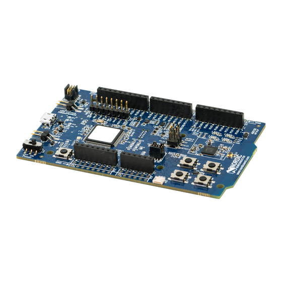
• Drag-and-drop Mass Storage Device (MSD) programming • Supporting NFC-A listen mode For access to firmware source code, hardware schematics, and layout files, see www.nordicsemi.com. Figure 1: 1 × nRF52 Preview Development Kit board (PCA10036) and 1 × NFC adhesive tag 4397_497 v1.2... - Page 5 Introduction 4397_497 v1.2...
-
Page 6: Setting Up The Development Kit
Setting up the development kit Before you start developing, prepare your development kit hardware by completing a few easy steps and download the required software. 1. To set up the hardware, follow the instructions in Getting started with the nRF52 Development Kit. -
Page 7: Software Tools
Software tools We have an extensive range of supporting software tools to help you with testing and programming on your chip. • nRFgo Studio: This is our tool for programming and configuring devices. It supports the programming of nRF52 SoftDevices, applications, and bootloaders. nRF5 SDK: The nRF5 Software Development Kit (SDK) provides source code of examples and libraries •... -
Page 8: Start Developing
Start developing After you have set up the development kit and installed the toolchain, it is time to start developing. There are several ways to continue from here: • Running precompiled examples See the step by step instructions on how you can quickly test a precompiled example without having to use the full toolchain, it is a matter of copying and pasting a precompiled hex file onto your development kit board. -
Page 9: Interface Mcu
Figure 2: Interface MCU 5.1 IF Boot/Reset button The nRF52 Preview Development Kit board is equipped with a boot/reset button (SW5). This button is connected to the Interface MCU on the board and has two functions: • Resetting the nRF52832 device. -
Page 10: Interface Mcu Firmware (Fw)
Interface MCU • Flexible baudrate setting up to 1 Mbps. • Dynamic Hardware Flow Control (HWFC) handling. • Tri-stated UART lines when no terminal is connected. Table 1: Relationship of UART connections on nRF52832 and Interface MCU on page 10 shows an overview of the UART connections on nRF52832 and the interface MCU. - Page 11 Interface MCU Important: • Windows might try to defragment the MSD part of the interface MCU. If this happens, the interface MCU will disconnect and be unresponsive. To return to normal operation, the development kit must be power cycled. • Your antivirus software might try to scan the MSD part of the interface MCU. It is known that a certain antivirus program triggers a false positive alert in one of the files and quarantines the unit.
-
Page 12: Hardware Description
Hardware description The nRF52 Preview Development Kit board (PCA10036) can be used as a development platform for the nRF52832 device. It features an onboard programming and debugging solution. In addition to radio communication, the nRF52832 device can communicate with a computer through a virtual COM port provided by the interface MCU. -
Page 13: Block Diagram
32.768 kHz 32 MHz Figure 5: nRF52 Preview Development Kit board block diagram 6.3 Power supply The nRF52 Preview Development Kit board has three power options: 5 V from the USB, external power supply, and coin cell battery. 4397_497 v1.2... - Page 14 Hardware description Figure 6: Power supply options The 5 V from the USB is regulated down to 3.3 V through an on-board voltage regulator. The battery and external power supply are not regulated. The power sources are routed through a set of diodes (D1A, D1B, and D1C) for reverse voltage protection, where the circuit is supplied from the source with the highest voltage.
-
Page 15: Connector Interface
Important: Connect only one power source at the time. Shorting the solder bridges removes the reverse voltage protection. 6.4 Connector interface Access to the nRF52832 GPIOs is available from connectors P2, P3, P4, P5, and P6. The P1 connector provides access to ground and power on the nRF52 Preview Development Kit board. 4397_497 v1.2... - Page 16 The signals are also available on connectors P7, P8, P9, P10, P11, and P12, which are on the bottom side of the board. By mounting pin lists on the connector footprints, the nRF52 Preview Development Kit board can be used as a shield for Arduino motherboards or other boards that follow the Arduino standard.
-
Page 17: Buttons And Leds
Hardware description Figure 10: Arduino signals routing on the nRF52 Preview Development Kit board 6.5 Buttons and LEDs The four buttons and four LEDs on the nRF52 Preview Development Kit board are connected to dedicated I/Os on the nRF52832 chip. Part... -
Page 18: I/O Expander For Buttons And Leds
6.5.1 I/O expander for buttons and LEDs The nRF52 Preview Development Kit board has an I/O expander to avoid conflicts with boards that follow the Arduino standard, the on-board GPIOs for the buttons and LEDs would otherwise possibly conflict with such boards. - Page 19 LED 4 Table 4: GPIO connection The I/O expander will release these GPIOs for general use when the nRF52 Preview Development Kit is used together with boards that follows the Arduino standard. The I/O expander can be permanently enabled by shorting solder bridge SB18 or permanently disabled by cutting the shorting track on SB19. You must also short SB18 when cutting SB19 for full compatibility with the Arduino standard.
-
Page 20: Khz Crystal
32.768 kHz crystal (X2) for higher accuracy and lower average power consumption. On the nRF52 Preview Development Kit board, P0.00 and P0.01 are by default used for the 32.768 kHz crystal and are not available as a GPIO on the connectors. -
Page 21: Measuring Current
Figure 16: 32.768 kHz crystal and SB1 to SB4 schematic 6.7 Measuring current The current drawn by the nRF52832 device can be monitored on the nRF52 Preview Development Kit board. To measure the current, you must first prepare the board by cutting the shorting of solder bridge SB9. -
Page 22: Rf Measurements
Virtual COM port. 6.8 RF measurements The nRF52 Preview Development Kit board is equipped with a small size coaxial connector (J1) for conducted measurements of the RF signal. The connector is of SWF type from Murata (part no. MM8130-2600) with an internal switch. By default, when there is no cable attached, the RF signal is routed to the on-board PCB trace antenna. -
Page 23: Debug Input
Hardware description Figure 19: Connecting a spectrum analyzer The connector and test probe will add loss to the RF signal which should be taken into account when doing measurements, see Table 6: Typical loss in connector and test probe on page 23. Frequency (MHz) Loss (dB) 2440... -
Page 24: Debug Output
Figure 20: Debug input connector 6.10 Debug output The nRF52 Preview Development Kit board supports programming and debugging external boards. To debug an external board, connect to the Debug out connector (P19) with a 10 pin cable. Figure 21: Debug output connector When the external board is powered, the interface MCU will detect the supply voltage of the board and program/debug the target chip on the external board instead of the on-board nRF52832. -
Page 25: Nfc Antenna Interface
Hardware description 6.11 NFC antenna interface The nRF52 Preview Development Kit board supports a Near Field Communication (NFC) tag. NFC-A listen mode operation is supported on nRF52832. The NFC antenna input is available on connector P23 on the nRF52 Preview Development Kit board. - Page 26 Hardware description Figure 23: NFC input schematic 4397_497 v1.2...
-
Page 27: Legal Notices
Nordic Semiconductor ASA customers using or selling these products for use in such applications do so at their own risk and agree to fully indemnify Nordic Semiconductor ASA for any damages resulting from such improper use or sale.
Need help?
Do you have a question about the nRF52 Preview Development Kit and is the answer not in the manual?
Questions and answers