Table of Contents
Advertisement
Quick Links
Instruction Manual
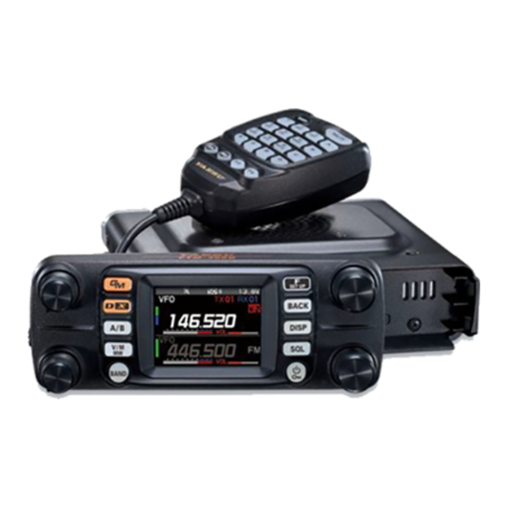
The ADMS-12 software provides convenient editing of the FTM-300DR/DE memory channel
frequencies, channel information and alpha tags, using a personal computer. Also, the
transceiver parameters and the setup menu items may be edited and configured easily from
the computer keyboard.
Data files (********.FTM300D) saved on the PC with prior ADMS-12 Ver. 1.0.0.0 may not be opened with the
new version of ADMS-12.
In such a case, after installing the latest version of ADMS-12, load the memory channel and set mode data
from the FTM-300DR/DE and save the file on the PC.
ADMS-12
Important Notice
YAESU MUSEN CO., LTD.
Advertisement
Table of Contents

Related Manuals for Yaesu ADMS-12


Summary of Contents for Yaesu ADMS-12
- Page 1 Data files (********.FTM300D) saved on the PC with prior ADMS-12 Ver. 1.0.0.0 may not be opened with the new version of ADMS-12. In such a case, after installing the latest version of ADMS-12, load the memory channel and set mode data from the FTM-300DR/DE and save the file on the PC.
-
Page 2: Table Of Contents
Necessary PC peripheral interfaces ......4 Window ............... 21 Trademarks ............4 Setting the Template Items ....22 The flow of a setup of ADMS-12 ......5 Memory ............... 22 Setup of ADMS-12 ........6 • Memories ..............22 Preparation ..............6 •... - Page 3 • Offset Direction ............26 • Operating Mode ............26 • DIG/ANALOG ............26 • Name ..............26 • Tone Mode .............. 26 • CTCSS Frequency ..........27 • DCS Code .............. 27 • User CTCSS ............27 • RX DG-ID ............... 27 •...
-
Page 4: Introduction
• Do not resell the software or manuals. • All responsibility for the use of this software lies with the customer. Yaesu cannot be held re- sponsible in any way for any damages or losses, which may be incurred by the customer as a result of using this software. -
Page 5: System Requirements
System Requirements Supported Operating Systems Microsoft Windows ® ® Microsoft Windows ® ® Microsoft Windows ® ® The performance of the CPU must satisfy the operating system requirements. RAM (System Memory) The capacity of the RAM (system memory) must be more than sufficient to satisfy the operating system requirements. -
Page 6: The Flow Of A Setup Of Adms-12
The flow of a setup of ADMS-12 The procedure when using ADMS-12 for the first time is as follows: ADMS-12 Programming Software Installation (6 page) ↓ SCU-58/SCU-40 USB Driver Software Installation (7 page) ↓ Connect the FTM-300DR/DE and the PC (7 page) ↓... -
Page 7: Setup Of Adms-12
Preparation Download the ADMS-12 software from the Yaesu Website for details (http://www.yaesu.com/). Download the ADMS-12 Programming Software to the same folder, and extract the downloaded zip file. ADMS-12 Programming Software Installation 1. Start up the computer as an “Administrator” user. -
Page 8: Scu-58/Scu-40 Usb Driver Software Installation
Before using the SCU-56/SCU-20 PC connection cable, installation of the driver software for the SCU-58/ SCU-40 is required. Download the driver software for the SCU-58/SCU-40 in advance. Download the designated driver software from the Yaesu website (http://www.yaesu.com/). Read the installation manual thoroughly and install the driver. The SCU-56/SCU-20 is included in the optional SCU-58/SCU-40 WIRES X Connection Cable Kit. -
Page 9: Execute Adms-12
Click “Exit” in the “File” menu to close the ADMS-12. Be sure to read the transceiver data information before using ADMS-12 It is necessary to read the data information from the transceiver first. If the data is not read, it will not be possible to load the saved file or transfer the data to the transceiver. -
Page 10: Display Examples
Display examples First Screen This is the first screen to be displayed when starting the ADMS-12 software. Menu Bar Click the left mouse button on each Menu in the Menu bar to import/export the setting data file, get data form FTM-300DR/DE and send data to FTM-300DR/DE. -
Page 11: Set Mode Screen
Set mode screen Basic setting items which are not related to memory channels can be configured from “Set Mode”. Click the left mouse button on “Settings” in the “Settings” menu to open the item “Set Mode” window. For more details, see “Set Mode”. -
Page 12: Names And Functions Of Menu Bar
Names and Functions of Menu Bar File • New Click the “New” parameter in the “File” menu to open a new configuration file. Multiple configuration files may be created and opened at the same time. Standard values are preset for each memory channel, VFO and set mode. •... -
Page 13: Import
• Import ADMS-12 data files may be created using a spreadsheet such as Microsoft Excel. To create a data file for the import of data, save the spreadsheet in the “CSV” comma separated file format. A spreadsheet may be easily created by exporting the template data in the “CSV” format using the ADMS- 12 “Export”... -
Page 14: Import With Ft3D Format
To change the specific printer settings, go to the Printer properties by clicking the the “Printer setup” button. • Exit To exit the ADMS-12 programmer, click the “Exit” parameter in the “File” menu to close the ADMS-12 soft- ware. If the following pop-up screen appears to confirm saving, follow the on-screen instruction to select the... -
Page 15: Edit
Edit Click the row to edit, then perform the following each operations. Part of setting items of each row cannot be cut, copy, and paste is not possible. • Undo To undo the edited data, click the “Undo” parameter in the “Edit” menu. •... -
Page 16: Find Next
• Find Next Click the “Find Next” parameter in the “Edit” menu to move to the next candidate character string. • Go to Channel Move the cursor to the desired channel, click the “Goto Channel” parameter in the “Edit” menu to open the screen where you can specify the channel you want to move to. -
Page 17: Add Frequency Range
• Add Frequency Range New channels may be created in designated frequency steps from the starting frequency by clicking the left mouse button on the “Add Frequency Range” parameter in the “Edit” menu. The “Add Frequency Range” window will open. A specified number of memory channels may be created, beginning from the starting frequency in the specified frequency steps. -
Page 18: Communications (Data Communication With The Ftm-300Dr/De)
Communications (Data communication with the FTM-300DR/DE) Get Data from SD card This command imports the settings data from the microSD memory card to the ADMS-12 programmer, and creates a new data file. 1. Insert the microSD memory card with the saved data from FTM-300DR/DE to the computer. -
Page 19: Send Data To Sd Card
Send Data to SD card Memories and settings from the ADMS-12 programmer may be transferred to the microSD memory card. 1. Insert a microSD memory card to write data for transfer from PC to FTM-300DR/DE. 2. Click [Send Data to SD card] in the “Communications” menu, then select the data area to write from the following. -
Page 20: Get Data From Ftm-300D
Get Data from FTM-300D This command transfers the settings data of the FTM-300DR/DE to the ADMS-12 programmer. To commu- nicate with the FTM-300DR/DE and create a new data file. Click the [Get Data from FTM-300D] parame- ter in the “Communications” menu. The “Get Data From FTM-300D” window will open. Connect the PC connection cable SCU-56 or SCU-20 between the FTM-300DR/DE and the computer. -
Page 21: Settings
From the set mode menu, you can customize the various functions of the FTM-300DR/DE according to your preferences. The ADMS-12 software displays the set mode menu in an easy-to-understand manner where you can change and save the setting values. Click the “Settings” parameter in the “Settings” menu to open the “SetMode” window. -
Page 22: Tool Bar
A check mark appears next to the “Status Bar” parameter when the Status Bar is displayed. Window This menu sets the operating window parameters of the ADMS-12 programmer. • Click the “Tile (up and down)” parameter in the “Window” menu to display multiple template files by dividing the window into two lists (upper and lower parts). -
Page 23: Setting The Template Items
Setting the Template Items Memory Use this page to edit the Memory channels data, Skip Memory channels, or PMS (Programmable Memory Scan) memory channels. • Memories Enter and edit the frequencies you normally use to the memory channels. Up to 999 channels can be registered. -
Page 24: Operating Mode
• Operating Mode Select the operating mode for receive channel. The selected frequency band is set to FM mode. The selected frequency band is set to AM mode. • DIG/ANALOG The AMS, V/D mode (DN), the Voice FR mode (VW) and the ANALOG mode (FM/AM mode) are select- able. -
Page 25: Vfo A / Vfob
• Receive Frequency Enter the VFO frequencies for each band. The FTM-300DR/DE default Frequencies are pre-entered into the ADMS-12 standard template. A frequency that is out of the transceiver’s range cannot be entered. When the error pop-up window is opened, enter the correct frequency. -
Page 26: Dig/Analog
• DIG/ANALOG The AMS, V/D mode (DN), the Voice FR mode (VW) and the ANALOG mode (FM/AM mode) are select- able. When the Setup Menu [TX/RX] [2 DIGITAL] [5 DIGITAL VW] is set to “ON”, the Voice FR mode (VW) can be selected. -
Page 27: Home A / Home B
• Receive Frequency / Transmit Frequency Enter any desired changes into Home Channel frequency. The FTM-300DR/DE default Frequencies are pre-entered into the ADMS-12 standard template. A frequency that is out of the transceiver’s range cannot be entered. When the error pop-up window is opened, enter the correct frequency. - Page 28 • CTCSS Frequency This item selects the Tone Frequency of the Tone Squelch. • DCS Code Select the DCS code when DCS is set. • User CTCSS Select the idle line frequency to remove signals such as idle line signals used by private railways and con- trol signals of MCA radio system.
- Page 29 Troubleshooting • The FTM-300DR/DE cannot receive or transmit data to the computer. • The Data transfer does not start. • Verify that the programming cable is correctly connected to the FTM-300DR/DE data port and to the Computer. Connect correctly. • Is the computer COM Port setting correct? Set the COM Port correctly.
- Page 30 Copyright 2022 YAESU MUSEN CO., LTD. All rights reserved. No portion of this manual may be reproduced without the permission of YAESU MUSEN CO., LTD. YAESU MUSEN CO., LTD. Tennozu Parkside Building 2-5-8 Higashi-Shinagawa, Shinagawa-ku, Tokyo 140-0002 Japan YAESU USA 6125 Phyllis Drive, Cypress, CA 90630, U.S.A.
Need help?
Do you have a question about the ADMS-12 and is the answer not in the manual?
Questions and answers