
Subscribe to Our Youtube Channel
Related Manuals for TAVRIDA ELECTRIC VCB15


Summary of Contents for TAVRIDA ELECTRIC VCB15
- Page 1 WITHDRAWABLE VCB VACUUM 17,5 kV, …31,5 kA, …3150 A CIRCUIT 24 kV, …25 kA, …2500 A BREAKER PRODUCT GUIDE VERSION 6...
-
Page 3: Table Of Contents
Contents 1. Introduction ..............................5 1.1 Abbreviations ............................ 6 1.2 Definitions ............................7 1.3 Disclaimers ............................7 1.4 Precautions ............................7 1.5 Warranty ............................8 2. Presentation ..............................9 2.1 Product Application Field ........................10 2.2 Key Benefits ............................10 2.3 Compliance ............................ -
Page 5: Introduction
1. Introduction... -
Page 6: Abbreviations
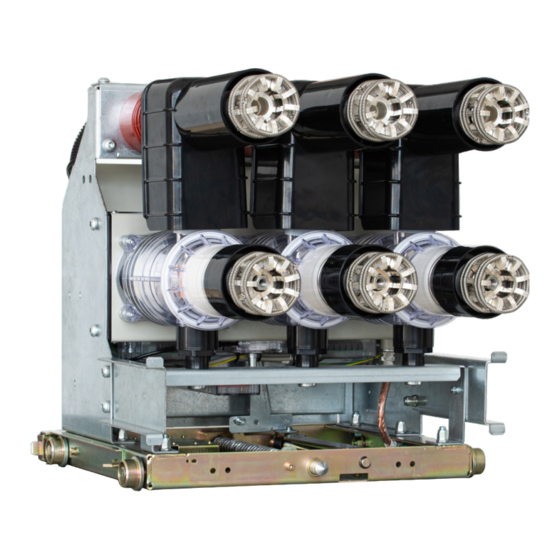
The breakers consist of the following main components: • Indoor Switching Module (ISM) - The air-insulated ISM incorporates Tavrida Electric vacuum interrupters incorporated in solid dielectric insulator controlled by per phase monostable magnetic actuators. No SF-6 or oil insulation is used in the ISM. -
Page 7: Definitions
1.3 Disclaimers Tavrida Electric will not accept any claims for damages caused by improper transport, storage as well as unpacking. Transport damage must be reported in writing to the supplier as soon as it is discovered. -
Page 8: Warranty
1.5 Warranty Unless otherwise stated in the contract, the warranty period is stated in Standard Warranty Policy. If otherwise agreed to, the contract conditions apply. No warranty is given in the following cases: a) The warranty period has run out during the period of storage with the customer. b) The operating conditions, ambient conditions, transport and storage conditions have not been adhered to according to the application description or the Installation and Operating Instructions. -
Page 9: Presentation
2. Presentation... -
Page 10: Product Application Field
• Switching different types of load in normal and fault modes. • Isolating faults in the cable or overhead network. Due to their short closing and opening times (see “Technical Parameters” on page 23), Tavrida Electric circuit breakers can bring significant benefits to the following applications: •... -
Page 11: Product Coding
3. Product Coding... -
Page 12: Circuit Breaker Coding
CM and VCB implementation type Table 1 - Product Group Description Code Description VCB15 Vacuum Circuit Breaker with rated voltage up to 17.5 kV VCB25 Vacuum Circuit Breaker with rated voltage up to 24 kV Table 2 - ISM Type Description... - Page 13 Table 4 - Circuit Breaker Parameters Description Parameter Parameter description Applicable options Code 150 mm Par5 Phase center distance 210 mm 275 mm 205 mm Par6 Terminal centre distance 310 mm 260 mm 280 mm Par7 Lower terminal height 325 mm 345 mm Basic circuit breaker functionality Par8...
- Page 14 The nameplate contains information about the VCB type, the VCB technical parameters and the serial number. The placement of the electrical data label is shown below. ISM electrical data label ISM electrical data label a) VCB15_LD8_16D labeling b) VCB15_MD1_16D labeling ISM electrical data label ISM electrical data label c) VCB15_HD1_16D labeling...
-
Page 15: Circuit Breaker Component Coding
3.2 Circuit Breaker Component Coding 3.2.1 ISM Coding ISM15_MD_1(Par1_(Par2)) Indoor switching module Rated voltage ISM type The following ISM types are available: • ISM15_LD_8(Par1_Par2) – Three-phase Light duty Indoor switching module with rated normal current up to 800 A. • ISM15_MD_1(Par1_Par2) – Medium duty indoor switching module with rated normal current up to 1250 A. •... -
Page 16: Cm Coding
3.2.2 CM Coding CM_16_1(Par1_Par2_Par3_Par4_Par5) Control module Control module series CM type Table 6 - CM Parameters Description Parameter Parameter Applicable options Code description English Par1 Language Spanish Portuguese Rated supply voltage 24-60V DC, version 2 60.2 Par2 and CM hardware 110-220 V AC/DC, version 2 220.2 version... - Page 17 Figure 7 Information label with terminals connections and main parameters 1. Serial number label 2. Label with applicable ISM designation 3. Warning label 4. Firmware version label 5. Information label with terminals connections and main parameters Figure 8 CM labels arrangement...
-
Page 18: Auxiliary Plugs Kit Coding
3.2.3 Auxiliary Plugs Kit Coding CBkit_Plug_1(Par1) Circuit breaker kit Auxiliary plugs kit Kit type CBkit_Plug_1 is used to provide a counterpart for the DOU auxiliary circuits connector in the switchgear panel. Table 7 - Circuit Breaker Kit Parameters Description Parameter Parameter description Applicable options Code... -
Page 19: Optional Main Circuits Connectors Kit Coding
3.2.4 Optional Main Circuits Connectors Kit Coding SGkit_Connector_1(Par1_Par2) Switchgear kit Main circuits connector kit Kit type The SGkit_Connector_1 is used to provide the switchgear fixed contact counterpart for the DOU main circuits connection. Table 8 - Switchgear Kit Parameters Description Parameter Parameter description Applicable options... -
Page 20: Optional Circuit Breaker Interlock Kit Coding
3.2.5 Optional Circuit Breaker Interlock Kit Coding CBkit_Interlock_6(Par1) Circuit breaker kit Interlock kit Kit type The CBkit_Interlock_6 is used with the DOU to provide it with optional interlock in case this interlock is required after DOU production. The interlock blocks the DOU rack in/out functionality in case auxiliary voltage (provided for solenoid installed on DOU plate) is unavailable. -
Page 21: Optional Kit For Control Module Installation On A Din Rail
3.2.6 Optional Kit for Control Module Installation on a DIN Rail CBmount_CM_1 Circuit breaker mounting kit Control module Kit type The CBmount_CM_1 is used to mount CM_16_1 on DIN rail. Figure 13 CBmount_CM_1... -
Page 22: Optional Manual Generator Coding
3.2.7 Optional Manual Generator Coding CBunit_ManGen_N(Par1) Circuit breaker unit Manual generator Generator type CBunit_ManGen is used to charge the CM_16_1 in cases where the main auxiliary power supply is not available. Table 10 - Generator Type Description Code N Description Manual generator for use with CM_16_1(Par1_220.2_Par3_Par4_Par5) Manual generator for use with CM_16_1(Par1_60.2_Par3_Par4_Par5) Table 11 - CBunit_ManGen Parameters Description... -
Page 23: Technical Parameters
4. Technical Parameters... - Page 24 Main technical data and circuit breaker technical parameters are presented in the tables below. Table 12 - VCB15 Technical Parameters Type VCB15_LD8 VCB15_MD1 VCB15_HD1 Rated voltage (Ur) 17.5 kV 17.5 kV 17.5 kV Phase centre distance (PCD), mm 210/275 Rated normal current (Ir)
- Page 25 Table 12 - VCB15 Technical Parameters Type VCB15_LD8 VCB15_MD1 VCB15_HD1 Altitude above sea level 1000 m Relative humidity in 24 hours ≤ 95 % Relative humidity over 1 month ≤ 90 % Temperature Range -25 °C ... +55 °C Degree of protection of main circuit terminals in accordance with IEC 60529...
- Page 26 Table 12 - VCB15 Technical Parameters Type VCB15_LD8 VCB15_MD1 VCB15_HD1 Preparation time for the close operation of the CM after a previous close operation ≤ 10 s Preparation time for the trip operation of the CM after switching on the auxiliary power supply ≤...
- Page 27 Table 12 - VCB15 Technical Parameters Type VCB15_LD8 VCB15_MD1 VCB15_HD1 “Close” and “Trip” Dry Contacts Inputs of the CM Output voltage ≥ 30 V Contacts closed current ≥ 50 mA Steady state current ≥ 5 mA 1) The rating depends on the metal-enclosed switchgear ventilation. Temperature rise type test at 2500 A in Cradle was successfully passed in KEMA.
- Page 28 Table 13 - VCB25 Technical Parameters Type VCB25_Shell2 Rated voltage (Ur) 24 kV Phase centre distance (PCD), mm 210/275 630 A Rated normal current (Ir) 2500 A 1250 A Rated power frequency withstand voltage (Ud) 60 kV Rated lightning impulse withstand voltage (peak) (Up) 125 kV Rated short-circuit breaking current (Isc) 25 kA...
- Page 29 Table 13 - VCB25 Technical Parameters Type VCB25_Shell2 Weight (depending on Phase Centre Distance) 101-190 kg Altitude above sea level 1000 m Relative humidity in 24 hours ≤ 95 % Relative humidity over 1 month ≤ 90 % Temperature Range -25 °C ...
- Page 30 Table 13 - VCB25 Technical Parameters Type VCB25_Shell2 Preparation time for the operation of the CM after switching on the auxiliary power supply ≤ 15 s Preparation time for the close operation of the CM after a previous close operation ≤...
- Page 31 Table 13 - VCB25 Technical Parameters Type VCB25_Shell2 Switching time 5 ms “Close” and “Trip” Dry Contacts Inputs of the CM Output voltage ≥ 30 V Contacts closed current ≥ 50 mA Steady state current ≥ 5 mA 1. At 34 % DC component. 2.
- Page 32 Table 14 - CM EMC Parameters Parameter Applicable standard Rated Value Electromagnetic Compatibility (EMC) Requirements IEC 60255-26 8 kV contact Electrostatic discharge IEC 61000-4-2 15 kV air 80 MHz – 3 GHz IEC 60255-26 Radiated EM field Immunity Sweep & spot IEC 61000-4-3 AM 1 kHz 80% 10 V/m IEC 60255-26...
-
Page 33: Design And Operation
5. Design and Operation... -
Page 34: Design
5.1 Design 5.1.1 Draw-Out Unit The draw-out plate, with its racking mechanism, allows the VCB to be racked into or out of the service position to test positions inside the switchgear. The main position indicating device is mechanically joined with the synchronizing shaft of the ISM to reliably indicate the status of the ISM. - Page 35 Control wiring plug Figure 18 Main contacts position indication VCB15_MD1_16D PCD 150 mm Manual trip button Racking mechanism of draw-out plate Fixing mechanism of draw-out plate Main contact upper terminal Main contact lower terminal Draw-out plate auxiliary switches module Control wiring plug Figure 19 Main contacts position indication VCB15_HD1_16D 3150 A, PCD 275 mm...
-
Page 36: Indoor Switching Module
The draw-out plate auxiliary switches module is not shown in the Figure 20. 5.1.2 Indoor Switching Module The Tavrida Electric vacuum circuit breaker consists of two main components: • The ISM (ISM15_LD_8 - Figure 21; ISM15_MD_1 – Figure 22; ISM15_HD_1 – Figure 23; ISM25_Shell_2 - Figure 24);... - Page 37 The result is up to 30,000 CO cycles at rated current or up to 50 operations at maximum short-circuit breaking current without replacing or adjusting any parts of the circuit breaker. Tavrida Electric vacuum circuit breakers are completely maintenance-free over a total life expectancy of at least 30 years.
-
Page 38: Control Module
ISM15_LD_8, ISM15_MD_1, ISM15_HD_1 and ISM25_Shell_2 interface 5.1.3 Control Module Tavrida Electric Control modules provide the following advantages: Low Power Consumption Low energy required to close or trip the ISM, no energy consumption by the ISM in its closed or open state and optimization of the CM electrical diagrams leads to low CM power consumption –... -
Page 39: Operation
Earthing stud Terminals for power supply Terminals for I/O (control and indication) Terminals for Switching Module “Power“ LED indicator USB port (for CM programming during production, not used under service conditions) “Malfunction“ LED indicator “Ready“ LED indicator Figure 27 CM_16_1 5.2 Operation 5.2.1 VCB Racking In and Out of the Switchgear To change the VCB position from test to service and vice versa, the DOU plate is equipped with a racking mechanism. -
Page 40: Ism Closing
5.2.2 ISM Closing To close the ISM main contacts, the CM close command should be applied. It is a “dry contact“ input; no external voltage is required. The close command will be accepted in the following cases: • The CM state is “Ready” (Ready LED flashes green). •... -
Page 41: Ism Emergency Opening
5.2.4 ISM Emergency Opening The ISM can also be opened manually. To open the ISM manually, apply force to the manual trip button. See Figure 31 below. Figure 31 ISM manual trip execution The button moves the ISM synchronization plate. When the synchronizing plate is moved, a force exceeding the magnetic attraction forces of the ring magnet is applied to the ISM armature, which subsequently starts to move. -
Page 43: Functionality
6. Functionality... -
Page 44: Interlocks
6.1 Interlocks The VCB provides all the interlocks required to provide high level of safety and reliability during installation, commissioning and operation. Standard safety interlocks included: • The draw-out unit can only be moved in case the ISM is open and locked against closing. •... -
Page 45: Optional Interlocks
6.2 Optional interlocks Optionally the VCB can be equipped with the following interlocks (in any combination): • The Interlock preventing VCB auxiliary circuits plug connection to the switchgear if the VCB is not in the test position. The interlock is available when the VCB has plastic auxiliary circuits plug. In case the VCB has IP2X front cover it is already equipped with this interlock;... - Page 46 The self-diagnostic system inside the CM detects possible malfunctions and reports them via the Malfunction LED blink signals and “Malfunction or Loss of auxiliary supply” relay state. Detailed explanations of the blink codes are provided in the Table 15. Table 15 - CM Self-Diagnostic Indication Indication Type of CM State...
- Page 47 The CM performs the checkup of ISM main contacts position and updates the “ISM Main Contacts Position” relay status in the following cases: • If the Close command was applied from the CM. In this case, the update is performed within 150 ms after the ISM main contacts closing.
-
Page 49: Application Notes
7. Application Notes... -
Page 50: Protective Earthing
7.1 Protective Earthing The draw-out unit is earthed by the truck wheels. Optionally the earthing can be arranged via the earthing bar connected to the bottom of the truck. In this case, corresponding earthing must be made in the switchgear (not as part of the delivery). earthing bars a) Standard Draw-Out plate b) The Draw-Out plate for VCB with PCD of 275 mm only... -
Page 51: Secondary Equipment
7.3 Secondary Equipment 7.3.1 VCB Secondary Connections The secondary circuits cable of the VCB can either be equipped by a plastic (58 pins) or a metal (108 pins) plug. The arrangement of the secondary plugs is presented in Table 16 (Plastic Plug Arrangement) and in Table 17 (Metal Plug Arrangement). - Page 52 Table 17 - Metal Plug Arrangement Pin No Connection Pin No Connection ISM auxiliary switch XT2.7 ISM auxiliary switch XT2.9 ISM auxiliary switch XT2.11 ISM auxiliary switch XT3.7 ISM auxiliary switch XT3.9 Actuator coil XT1.1 ISM auxiliary switch XT3.11 ISM auxiliary switch XT2.1 ISM auxiliary switch XT2.3 ISM auxiliary switch XT2.5 ISM auxiliary switch XT3.1...
- Page 53 Table 17 - Metal Plug Arrangement Pin No Connection Pin No Connection DOU plate position switch SQ1.9 DOU plate position switch SQ1.10 DOU plate position switch SQ1.11 DOU plate position switch SQ1.12 Earthing Figure 39 The metal plug with 108 pins...
-
Page 54: Cm Secondary Connections
Relay functionality and the number of relays which share the same functionality can be changed upon request. Please contact the nearest Tavrida Electric sales representative for more information. The CM is connected only to the ISM actuator coil circuits. The position of the ISM main contacts is determined by... -
Page 55: Auxiliary Supply
7.3.3 Auxiliary supply Connection of CM_16_1 to power supply is shown below. ~ (+) ~ (-) Power supply inputs Figure 41 CM_16 power supply connection The type of MCB shall be selected according to the CM consumption data given in Chapter 4. If the manual generator CBunit_ManGen is used for charging, its DC voltage outputs should be connected to power supply inputs of CM_16_1. -
Page 57: Appendix 1. Type Tests
Appendix 1. Type Tests... - Page 58 Type Tests of ISM15_MD Test center Standard Chapter Test name Test report name IEC 62271-100 6.2.6.1 Power-frequency withstand voltage test KEMA KEMA 1398-18 IEC 62271-100 6.2.6.2 Lightning impulse withstand voltage test KEMA KEMA 1398-18 IEC 62271-100 6.2.9 Partial discharge tests KEMA KEMA 1398-18 IEC 62271-100...
- Page 59 Type Tests of ISM15_HD Test center Standard Chapter Test name Test report name KEMA 1656-18 KEMA IEC 62271-100 6.2.6.1 Power-frequency withstand voltage test KEMA 1717-18 KEMA 1656-18 KEMA IEC 62271-100 6.2.6.2 Lightning impulse withstand voltage test KEMA 1717-18 KEMA 1656-18 KEMA IEC 62271-100 6.2.9...
- Page 60 Type Tests of CM_16 Standard Test name Test center name Test report IEC 60255-26 Electrostatic discharge immunity test KEMA KEMA TIC 1371-14 IEC 61000-4-2 IEC 60255-26 Radiated electromagnetic field immunity test KEMA KEMA TIC 1371-14 IEC 61000-4-3 IEC 60255-26 IEC 62271-1 Fast transient burst immunity test KEMA KEMA TIC 1371-14...
-
Page 61: Appendix 2. Withdrawable Vcb Package Dimensions
Appendix 2. Withdrawable VCB Package Dimensions... - Page 62 Withdrawable VCB Package Dimensions Package Dimensions, Withdrawable VCB not more than (LxWxH), mm 780x780x937 VCB15_LD8_16D 780x780x937 780x780x937 VCB15_MD1_16D 780x780x937 780x780x937 VCB15_HD1_16D 1150x990x997 905x805x997 VCB25_Shell2_16D 1150x990x997...
-
Page 63: Appendix 3. Overall Drawings
Appendix 3. Overall Drawings... - Page 64 VCB15_LD8_16D VCB15_LD8_16D = 687 mm 17.5kV, 800 A, PCD: 150 mm, = 535 mm weight: 70 kg = 528 mm...
- Page 65 VCB15_LD8_16D = 677 mm 17.5kV, 800 A, PCD: 210 mm, = 682 mm weight: 76 kg = 528 mm...
- Page 66 VCB15_LD8_16D = 687 mm 17.5kV, 800 A, PCD: 150 mm, with IP2X front cover, = 535 mm weight: 74 kg = 633 mm...
- Page 67 VCB15_LD8_16D = 677 mm 17.5kV, 800 A, PCD: 210 mm, with IP2X front cover, = 682 mm weight: 81 kg = 633 mm...
- Page 68 VCB15_MD1_16D VCB15_MD1_16D = 677 mm 17.5kV, 1250 A, PCD: 150 mm, = 535 mm weight: 72 kg = 515 mm...
- Page 69 VCB15_MD1_16D = 677 mm 17.5kV, 1250 A, PCD: 210 mm, = 682 mm weight: 74 kg = 515 mm...
- Page 70 VCB15_MD1_16D = 677 mm 17.5kV, 1250 A, PCD: 150 mm, with IP2X front cover, = 535 mm weight 76 kg = 633 mm...
- Page 71 VCB15_MD1_16D = 677 mm 17.5kV, 1250 A, PCD: 210 mm, with IP2X front cover, = 682 mm weight 88 kg = 633 mm...
- Page 72 VCB15_HD1_16D VCB15_HD1_16D = 656.5 mm 17.5kV, 2500 A, PCD: 210 mm, = 682 mm weight: 128 kg = 704 mm...
- Page 73 VCB15_HD1_16D = 656.5 mm 17.5kV, 2500 A, PCD: 275 mm, = 882 mm weight: 140 kg = 704 mm...
- Page 74 VCB15_HD1_16D = 656.5 mm 17.5kV, 3150 A, PCD: 275 mm, = 882 mm weight: 158 kg = 704 mm...
- Page 75 VCB15_HD1_16D = 656.5 mm 17.5kV, 2500 A, PCD: 210 mm, with IP2X front cover, = 682 mm weight 133 kg = 704 mm...
- Page 76 VCB15_HD1_16D = 656.5 mm 17.5kV, 2500 A, PCD: 275 mm, with IP2X front cover, = 882 mm weight 147 kg = 704 mm...
- Page 77 VCB15_HD1_16D = 656.5 mm 17.5kV, 3150 A, PCD: 275 mm, with IP2X front cover, = 882 mm weight 165 kg = 742 mm...
- Page 78 VCB25_Shell2_16D VCB25_Shell2_16D = 813.5 mm 24kV, 630 A, PCD: 210 mm, 370 mm depth of movable part of cassette, = 682 mm weight: 101 kg = 695 mm...
- Page 79 VCB25_Shell2_16D = 813.5 mm 24kV, 1250 A, PCD: 210 mm, 370 mm depth of movable part of cassette, = 682 mm weight: 112 kg = 694 mm...
- Page 80 VCB25_Shell2_16D = 813.5 mm 24kV, 630 A, PCD: 275 mm, 370 mm depth of movable part of cassette, = 882 mm weight: 115 kg = 695 mm...
- Page 81 VCB25_Shell2_16D = 813.5 mm 24kV, 1250 A, PCD: 275 mm, 370 mm depth of movable part of cassette, = 882 mm weight: 126 kg = 694 mm...
- Page 82 VCB25_Shell2_16D = 803.5 mm 24kV, 2500 A, PCD: 275 mm, 370 mm depth of movable part of cassette, = 882 mm weight: 180 kg = 719 mm...
- Page 83 VCB25_Shell2_16D = 813.5 mm 24kV, 630 A, PCD: 210 mm, 420 mm depth of movable part of cassette, = 682 mm weight: 102 kg = 695 mm...
- Page 84 VCB25_Shell2_16D = 813.5 mm 24kV, 1250 A, PCD: 210 mm, 420 mm depth of movable part of cassette, = 682 mm weight: 113 kg = 694 mm...
- Page 85 VCB25_Shell2_16D = 813.5 mm 24kV, 630 A, PCD: 275 mm, 420 mm depth of movable part of cassette, = 882 mm weight: 117 kg = 695 mm...
- Page 86 VCB25_Shell2_16D = 813.5 mm 24kV, 1250 A, PCD: 275 mm, 420 mm depth of movable part of cassette, = 882 mm weight: 128 kg = 694 mm...
- Page 87 VCB25_Shell2_16D = 803.5 mm 24kV, 2500 A, PCD: 275 mm, 420 mm depth of movable part of cassette, = 882 mm weight: 163 kg = 719 mm...
- Page 88 VCB25_Shell2_16D = 813.5 mm 24kV, 630 A, PCD: 210 mm, 370 mm depth of movable part of cassette, with IP2X front cover, = 682 mm weight: 109 kg = 792 mm...
- Page 89 VCB25_Shell2_16D = 813.5 mm 24kV, 1250 A, PCD: 210 mm, 370 mm depth of movable part of cassette, with IP2X front cover, = 682 mm weight: 120 kg = 792 mm...
- Page 90 VCB25_Shell2_16D = 813.5 mm 24kV, 630 A, PCD: 275 mm, 370 mm depth of movable part of cassette, with IP2X front cover, = 882 mm weight: 124 kg = 792 mm...
- Page 91 VCB25_Shell2_16D = 813.5 mm 24kV, 1250 A, PCD: 275 mm, 370 mm depth of movable part of cassette, with IP2X front cover, = 882 mm weight: 135 kg = 792 mm...
- Page 92 VCB25_Shell2_16D = 803.5 mm 24kV, 2500 A, PCD: 275 mm, 370 mm depth of movable part of cassette, with IP2X front cover, = 882 mm weight: 190 kg = 836 mm...
- Page 93 VCB25_Shell2_16D = 813.5 mm 24kV, 630 A, PCD: 210 mm, 420 mm depth of movable part of cassette, with IP2X front cover, = 682 mm weight: 110 kg = 792 mm...
- Page 94 VCB25_Shell2_16D = 813.5 mm 24kV, 1250 A, PCD: 210 mm, 420 mm depth of movable part of cassette, with IP2X front cover, = 682 mm weight: 121 kg = 792 mm...
- Page 95 VCB25_Shell2_16D = 813.5 mm 24kV, 630 A, PCD: 275 mm, 420 mm depth of movable part of cassette, with IP2X front cover, = 882 mm weight: 126 kg = 792 mm...
- Page 96 VCB25_Shell2_16D = 813.5 mm 24kV, 1250 A, PCD: 275 mm, 420 mm depth of movable part of cassette, with IP2X front cover, = 882 mm weight: 137 kg = 792 mm...
- Page 97 VCB25_Shell2_16D = 803.5 mm 24kV, 2500 A, PCD: 275 mm, 420 mm depth of movable part of cassette, with IP2X front cover, = 882 mm weight: 173 kg = 836 mm...
- Page 98 Dimensions of Control Module 16 11 CM_16_1(Par1_Par2_Par3_Par4_Par5) = 165 mm Weight: 1 kg = 190 mm = 45 mm...
- Page 99 Dimensions of the Accessories Dimensions of Manual Generator CBunit_ManGen_1, CBunit_ ManGen_2 Control wiring plastic plug counterpart Control Wiring Plug Counterparts Control wiring plastic plug counterpart...
- Page 100 Control wiring metal plug counterpart Switchgear Fixed Contact Counterparts 17,5 kV, 1250 A fixed contact...
- Page 101 24 kV, 1250 A fixed contact 2000 A fixed contact...
- Page 102 3150 A fixed contact...
-
Page 103: Appendix 4. Secondary Schemes
Appendix 4. Secondary Schemes... - Page 104 VCB15_LD8_16D with Plastic Plug...
- Page 105 VCB15_LD8_16D with Metal Plug...
- Page 106 VCB15_MD1_16D with Plastic Plug...
- Page 107 VCB15_MD1_16D with Metal Plug...
- Page 108 VCB15_HD1_16D with Plastic Plug...
- Page 109 VCB15_HD1_16D with Metal Plug...
- Page 110 VCB25_Shell2_16D with Plastic Plug...
- Page 111 VCB25_Shell2_16D with Metal Plug...
-
Page 112: List Of Changes
List of Changes Documents Change Version Scope of change Reason of change version Date author 16.10.2018 Document creation Products development 21.02.2019 Mistypes correction Document elaboration 09.10.2019 Change of VCB, ISM and CM classification. Product range change 29.10.2019 Adding of the CBmount_CM_1 Product range change 21.05.2020 Adding of the new options... - Page 116 Tavrida Electric applies a policy of ongoing development and reserves the right to change product without notice. Tavrida Electric does not accept any responsibility for loss or damage incurred as a result of acting or refraining from action based on information in this document.
Need help?
Do you have a question about the VCB15 and is the answer not in the manual?
Questions and answers