Table of Contents
Advertisement
Advertisement
Table of Contents
Troubleshooting

Related Manuals for TAVRIDA ELECTRIC VCB Series


Summary of Contents for TAVRIDA ELECTRIC VCB Series
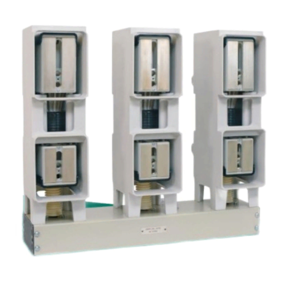
- Page 1 COMPATIBLE SERIES USER GUIDE...
-
Page 3: Table Of Contents
Contents Product description ............................5 1.1 Abbreviations ............................6 1.2 Main technical parameters ........................7 1.3 Disclaimers ............................. 12 1.4 Precautions ............................12 1.5 Warranty ..............................12 Nameplates and seals ..........................13 Product handling ............................18 3.1 Transportation ............................19 3.2 Storage 19 3.3 Unpacking and inspection ........................ -
Page 5: Product Description
1 Product description... -
Page 6: Abbreviations
The breakers are comprised of following main components: Indoor Switching Module (ISM) - The air insulated ISM incorporates Tavrida Electric vacuum interrupters with monostable magnetic actuators and solid dielectric insulating materials. No SF-6 or oil insulation is used in the ISM;... -
Page 7: Main Technical Parameters
1.2 Main technical parameters Main technical data and circuit breaker technical parameters are presented in the tables below. Table 1 - Main technical parameters Type VCB15_LD1 VCB15_LD3 VCB15_LD6 VCB15_LD8 VCB15_MD1 VCB15_MD3 VCB15_Shell2 VCB15_HD1 VCB25_LD1 VCB25_LD2 VCB25_LD3 Rated voltage (Ur) 12 kV 17.5 kV 12 kV 12 kV... - Page 8 Type VCB15_LD1 VCB15_LD3 VCB15_LD6 VCB15_LD8 VCB15_MD1 VCB15_MD3 VCB15_Shell2 VCB15_HD1 VCB25_LD1 VCB25_LD2 VCB25_LD3 Standards IEC 62271-100 GB 1984- 2003 IEC 62271-100 Mechanical vibration withstand capability according to Class 4M4 Class 4M4 Class 4M4 Class 4M4 Class 4M4 Class 4M4 Class 4M4 Class 4M4 Class 4M4 Class 4M4...
- Page 9 Type VCB15_LD1 VCB15_LD3 VCB15_LD6 VCB15_LD8 VCB15_MD1 VCB15_MD3 VCB15_Shell2 VCB15_HD1 VCB25_LD1 VCB25_LD2 VCB25_LD3 Design, switching capacity of gold-plated auxiliary contacts Number of available auxiliary contacts for three-phase 6 NO + 6 NC Minimum current for 5 V AC / DC 1 mA 1 mA 1 mA 1 mA...
- Page 10 Type VCB15_LD1 VCB15_LD3 VCB15_LD6 VCB15_LD8 VCB15_MD1 VCB15_MD3 VCB15_Shell2 VCB15_HD1 VCB25_LD1 VCB25_LD2 VCB25_LD3 Inrush current of ≤ 120 A CM_16_1(Par1_60.1_Par3_Par4_Par5) with discharged capacitors Inrush current of ≤ 18 A CM_16_1(Par1_220.1_Par3_Par4_Par5) with discharged capacitors Inrush time constant of ≤ 0.5 ms CM_16_1(Par1_60.1_Par3_Par4_Par5) with discharged capacitors Inrush time constant of ≤...
- Page 11 At 5 min short-term duty. Continuous current – 5 A. 15) Gold-plated auxiliary contacts are availbale on request. Contact your nearest sales representatives. In case of Dry contacts “Close” and “Trip” are open. At Cos j >0.66. At Cos j >0.33.
-
Page 12: Disclaimers
1.3 Disclaimers Tavrida Electric will not accept any claims for damages caused by improper transport, storage as well as unpacking. Transport damage must be reported in writing to the supplier as soon as it is discovered. The present User Guide contains information necessary for the installation, commissioning and operation. It is absolutely necessary for the proper use of the Vacuum Circuit Breakers to read the User Guide carefully before starting and to adhere to the instructions and the relevant regulations. -
Page 13: Nameplates And Seals
2 Nameplates and seals... - Page 14 The Vacuum Circuit Breakers itself does not have nameplates or seals but main components (ISM, CM and manual generators) it is comprised of have them. ISM nameplates and seals Each ISM has the following plate and labels: Label Serial number plate ...
- Page 15 c) ISM15_Shell_2 labeling d) ISM15_MD_1 labeling e) ISM15_HD_1 labeling Figure 4 Serial number and designation label arrangement CM nameplates and seals Each CM has the following labels: Serial number label Label with applicable ISM designation Warning label ...
- Page 16 Figure 7 Figure 8 Warning label Firmware version label Figure 9 Information label with terminals connections and main parameters Serial number label Label with applicable ISM designation Warning label Warranty seal Firmware version label Information label with terminals connections and main parameters Figure 10 CM labels placement...
- Page 17 Manual generator nameplates Each manual generator has the following labels: Designation label Serial number label Figure 11 Designation label Figure 12 Serial number label...
-
Page 18: Product Handling
3 Product handling... -
Page 19: Transportation
3.1 Transportation The VCBs are transported in the original packing only. Any kind of transport and combinations thereof are applicable. Transportation shall be provided in waterproof compartments. If air transport is used all products shall be transported inside heated, pressurized compartments. The packed goods shall be handled in accordance with the handling symbols. - Page 20 Figure 15 Lifting of ISM15_HD_1 All items should be checked visually for: mechanical damage, scratches, discoloration, corrosion; damage to the seals Figure 3, Figure 5). Any transport damage must be reported immediately to the carrier in writing. Damages shall be photographically documented.
- Page 21 The VCB scope of supply is presented in Appendix 1. This side up Fragile Protect from rain Max. weight on the delivery unit Figure 16 Label 1 Handling symbols Figure 17 Label 2 Logistics data Figure 18 Carton box VCB has in its package: Indoor Switching Module (ISM);...
- Page 22 Figure 20 CM packaging Manufacturer Type of device Product code Product name Serial number Handling symbols Figure 21 CM packaging labels The CM shall have undamaged warranty seals (its placement on the CM is shown in Figure 10). The CM designation and serial number shall comply with data in the VCB packing list and the CM routine test certificate (appearance of the CM serial number label and designation label are shown in Figure 5 and Figure 6, their placement on the CM –...
- Page 23 a) ISM b) screwdriver Unit_Screwdriver_1 Figure 23 ISM15_LD_1, ISM15_LD_3, ISM25_LD_1, ISM25_LD_2, ISM25_LD_3 scope of supply ISM15_LD_8 has different supply options. Depending on the order ISM15_LD_8 can be supplied with 1 set or 2 sets of auxiliary switches boards (with 3NO + 3NC, 4NO + 4NC, 6NO + 6NC contacts) or without them. In addition, the optional position indicator can be included in the package.
- Page 24 Each of ISM15_MD_1, ISM15_MD_3, ISM15_SHELL_2, ISM15_HD_1 is supplied with the following components: screwdriver Unit_Screwdriver_1 auxiliary board EA_ASboard_28 position indicator CBkit_PosInd_1 Figure 25 ISM15_MD_1 scope of supply a) ISM b) screwdriver Unit_Screwdriver_1 position indicator CBkit_PosInd_1 Figure 26 ISM15_MD_3 scope of supply...
- Page 25 position indicator screwdriver CBkit_PosInd_1 Unit_Screwdriver_1 Figure 27 ISM15_Shell_2 scope of supply screwdriver Unit_Screwdriver_1 auxiliary board EA_ASboard_28 position indicator CBkit_PosInd_1 Figure 28 ISM15_HD_1 scope of supply...
- Page 26 CBkit_Ins_3 scope of supply 24 kV variants of VCB25_LD1_16.F and VCB25_LD3_16.F include CBkit_Ins_3. As part of a VCB CBkit_Ins_3 is placed inside the VCB package. If the kit is delivered separately as a spare part of the VCB it is packed in a plastic bag.
- Page 27 Screw StandDet_Screw_DIN912(M16_100_Fe88-Zn) Screw StandDet_Screw_DIN912(M16_110_Fe88-Zn) Terminal CBdet_Terminal_1 Washer StandDet_Washer_DIN125-1A (17_Fe-Zn) Washer CBcomp_Washer_1 Plastic insulation CBdet_PlastIns_2(310_50_H) Plastic insulation CBdet_PlastIns_1(50) Figure 31 CBkit_Shell15_1(310) scope of supply Two variants of bolts are included in CBkit_Shell15_1: StandDet_Screw_DIN912(M16_100_Fe88-Zn) - for case of single busbar connection (10 mm thickness); ...
- Page 28 Indicator CBdet_Indicator_1 Lever CBunit_Lever_1 Plastic insulation CBdet_PlastIns_4 Plastic insulation CBdet_PlastIns_3(1) Plastic insulation CBdet_PlastIns_3(2) Plastic insulation CBdet_PlastIns_3(3) Rubber ring Det_RubberRing_12 Guide CBdet_Guide_1 Lever CBunit_Lever_1 Figure 33 CBkit_LD15_3 scope of supply VCB accessories unpacking and check CBkit_Interlock_1 packaging and scope of supply CBkit_Interlock_1 can be used with the VCB15_LD1_16.F and VCB25_LD1_16.F as an interface for various manual trip / indication / lockout accessories.
- Page 29 CBkit_Ins_4 scope of supply CBkit_Ins_4 provides the dielectric strength of busbars connection to the VCB15_MD1_16.F. The kit has components for one pole of ISM15_MD, so three such kits are necessary for one VCB15_MD1_16.F insulation and one – for VCB15_MD3_16.F. The kit is delivered separately and packed in a plastic bag. The kit includes one variant of the following options depending on the parameter value: Rubber insulator CBdet_RubberIns_2 Rubber insulator CBdet_RubberIns_3...
- Page 30 CBkit_Interlock_8 packaging and scope of supply CBkit_Interlock_8 can be used with the VCB15_Shell2_16.F only as an accessory. It is an interface for manual trip / lockout accessories connection to the ISM. The kit is packed in a cardboard box. Figure 38 CBkit_Interlock_8 packing Manufacturer Product name...
- Page 31 CBkit_Interlock_3 packaging and scope of supply CBkit_Interlock_3 can be used with the VCB15_Shell2_16.F via CBkit_Interlock_8 installed on this ISM, with VCB15_LD8_16.F, VCB15_MD1_16.F, VCB15_MD3_16.F and VCB15_HD1_16.F as an accessory for manual trip / lockout of the ISM by key switch. The kit is packed in a cardboard box. Figure 41 CBkit_Interlock_3 packing Manufacturer...
- Page 32 CBkit_Interlock_3 is used with the ISM15_LD_8, ISM15_MD_1, ISM15_MD_3 and ISM15_HD_1. In addition CBkit_Interlock_3 is used with the ISM15_Shell_2 via CBkit_Interlock_8 CBkit_Interlock_4 packaging and scope of supply CBkit_Interlock_4 can be used with the VCB15_Shell2_16.F via CBkit_Interlock_8 installed on this ISM, with VCB15_LD8_16.F, VCB15_MD1_16.F, VCB15_MD3_16.F and VCB15_HD1_16F as an accessory for manual trip / lockout of the ISM by rotary switch.
- Page 33 CBkit_Interlock_4 is used with the ISM15_LD_8, ISM15_MD_1, ISM15_MD_3 and ISM15_HD_1. In addition CBkit_Interlock_4 is used with the ISM15_Shell_2 via CBkit_Interlock_8 CBkit_Interlock_5 packaging and scope of supply CBkit_Interlock_5 can be used with the VCB15_Shell2_16.F via CBkit_Interlock_8 installed on this ISM, with the VCB15_LD8_16.F VCB15_MD1_16.F, VCB15_MD3_16.F and VCB15_HD1_16.F as an accessory for manual trip of the ISM as a manual trip button.
- Page 34 CBkit_Interlock_5 is used with the ISM15_LD_8, ISM15_MD_1, ISM15_MD_3 and ISM15_HD_1. In addition CBkit_Interlock_5 is used with the ISM15_Shell_2 via CBkit_Interlock_8. CBunit_ ManGen_1 and CBunit_ ManGen_2 packaging and scope of delivery CBunit_ManGen is used to charge the CM_16_1 in cases where the main auxiliary power supply is not available.
- Page 35 CBkit_PosInd_1 packaging and scope of supply CBkit_PosInd_1 is used to indicate the ISM main circuit position. VCB15_MD1_16.F, VCB15_MD3_16.F, VCB15_SHELL2_16.F, VCB15_HD1_16.F, and ISM15_Shell_2 already include CBkit_PosInd_1. In case of separate delivery the position indicator is packed in a plastic bag. Figure 53 CBkit_PosInd_1 scope of supply CBcomp_RelCable_3 packaging and scope of supply CBcomp_RelCable_3 is a flexible trip and lock cable used for connection of...
-
Page 36: Handling
Manufacturer Type of device Product name Product code Figure 56 CBmount_CM_1 package labeling 1. Holder CBunit_Holder_15 2. Washer StandDet_Washer_DIN127-A(4_Fe-Zn) 3. Screw StandDet_Screw_DIN7985-Ph(M4_12_Fe48-Zn) 4. Washer StandDet_Washer_DIN125-1A(4.3_Fe-Zn) 5. Screw StandDet_Screw_ISO7046-Ph(M4_6_Fe48-Zn) 6. Holder StandComp_Holder_DIN(1) Figure 57 CBmount_CM_1 delivery set 3.4 Handling To avoid equipment damage follow the handling recommendations listed below: handling in accordance with pictorial symbols;... -
Page 37: Installation
4 Installation... -
Page 38: Primary Part
4.1 Primary part Preparation The following regulations must be adhered to during installation, commissioning and operation: IEC 62271-1//DIN VDE 0101, General specification for high-voltage switchgear and control gear standards; VDE 0105, Operation of electrical installations; DIN VDE 0141, Earthing systems for electrical power installations with nominal voltages above 1 kV; ... - Page 39 Figure 58 Withdrawable unit with ISM15_HD_1, vertical arrangement, actuator down Figure 59 Figure 60 Fixed compact installation of ISM15_Shell_2, vertical Withdrawable unit with ISM15_MD_1, tilted arrangement, actuator up arrangement Busbars and cables shall be connected with the ISM primary terminals mechanically in a stress-free manner. No pressure, tension or torsion forces shall act on the ISM.
- Page 40 Figure 62 Bolt sizes and torques Figure 63 ISM15_LD_8 mounting points 1 - Mandatory mounting points, 3 – additional mounting points (required in case uncontrolled horizontal force will be applied to ISM terminals, ex. draw-out unit) Figure 64 Bolt sizes and torques for ISM15_LD_8...
- Page 41 Important: It is not allowed to perform any close or trip operation for ISM LD series while the nut M10 on the stud of the ISM upper terminal (Figure 62 and Figure 64) is not tightened. Eight threads on both sides of the frame for obligatory ISM fixing (M10, torque is 25±3 Nm).
- Page 42 To provide 95 kV BIL between ISM15_HD_1 main terminals and external frame, it is required to use the additional spacers. Spacers are included in the CBMount_ISM15_1 kit. Figure 68 ISM15_HD_1 mounting with help of spacers from CBmount_ISM15_1 Main terminal connections of ISM15_LD_1, ISM15_LD_3, ISM15_LD_6 , ISM15_LD_8 , ISM25_LD_1, ISM25_LD_2, ISM25_LD_3 Primary terminals connection Busbars can be connected to terminals of ISM LD series by means of M10 screws.
- Page 43 Electromagnetic clearances Short-circuit current magnetic field influences the ISM magnetic actuator. To avoid unwanted tripping, the minimum clearances between busbars and the ISM frame should be not less than 120 mm (Figure 69). Figure 69 Electromagnetic clearances Insulation clearances The recommended minimum phase-to-phase and phase-to-ground air clearances are stated in Table 3.
- Page 44 Figure 72 CBkit_Ins_3 installation If the insulation cap set CBkit_Ins_3 will not be used the compliance with the rated insulation level shall be verified by a voltage test. Busbar for 24 kV ISM If the PCD of the ISM25_LD_1 is 210 mm, the connected busbars shall have the shape as shown in Figure 73.
- Page 45 Figure 74 Figure 75 Edges of bars 40x10 mm at the place to ISM terminal Edges of bars 80x10 mm at the place to ISM connection terminal connection M12 bolts fixing busbars (or contact arms) to ISM15_MD_1 or ISM15_MD_3 terminals should be tightened with a torque of 50±2 Nm.
- Page 46 Figure 77 Details of ISM15_MD terminals connection to rectangular cross-shaped busbars (at fixed installation, for example) Figure 78 Figure 79 Details of ISM15_MD terminals connection to rectangular Details of ISM15_MD terminals connection to rectangular cross-shaped busbars with help of CBkit_Ins_4(1) (at fixed cross-shaped busbars with help of CBkit_Ins_4(2) (at fixed installation, for example) installation, for example)
- Page 47 The gap between the busbar and the ISM terminal just before this fastening should be not more than one millimeter. Details of ISM15_Shell_2 terminals Details of ISM15_Shell_2 terminals connection to rectangular cross-shaped connection to cylindrical cross- busbars (at fixed installation, for example) shaped busbars (withdrawable unit contact arm, for example) Details of ISM15_Shell_2 terminals...
- Page 48 Figure 81 Details of ISM15_HD_1 terminals connection to rectangular cross-shaped busbars (at fixed installation, for example) Figure 82 Figure 83 Details of ISM15_HD_1 terminals connection to single rectangular Details of ISM15_HD_1 terminals connection to double cross-shaped busbars (at fixed installation, for example) rectangular cross-shaped busbars (at fixed installation, for example) Electrodynamic forces clearances...
- Page 49 Figure 84 ISM support insulators installation distance Table 5 - Additional support insulators installation minimum distances Short-circuit current 20 kA 25 kA 31.5 kA L1, mm ISM15_MD_1(150_L) ISM15_MD_1(210_L) ISM15_MD_3 ISM15_MD_3 1100 ISM15_Shell_2(150_L) ISM15_Shell_2(210_L) ISM15_Shell_2(210_H) ISM15_Shell_2(275_H) 1200 ISM15_HD_1(210) 1000 ISM15_HD_1(275) 1000 1000 In case ISM15_MD_3 is installed close to the other ISM15_MD_3.
- Page 50 Figure 85 Electromagnetic clearances Table 6 - Electromagnetic clearances Short circuit current Minimum clearance (a) Applicable for 100 mm ISM15_MD_1 100 mm ISM15_MD_3 ≤20 kA 120 mm ISM15_Shell_2, ISM15_HD_1 120 mm ISM15_HD_1 120 mm ISM15_MD_1 120 mm ISM15_MD_3 25 kA 150 mm ISM15_Shell_2 190 mm...
- Page 51 Figure 86 Figure 87 ISM15_MD insulation clearances - 75 kV BIL ISM15_MD insulation clearances - 95 kV BIL...
- Page 52 Figure 88 Figure 89 ISM15_Shell_2 with low upper terminal insulation ISM15_Shell_2 with high upper terminal clearances insulation clearances Figure 90 ISM15_HD_1 insulation clearances Coordination of minimum clearances Based on electromagnetic influence and rated insulation voltage, the largest value clearance should be selected.
- Page 53 Figure 91 Interlocking interface of ISM15_LD_1, ISM25_LD_1, LD_2 A = 19,5...50 mm; B = 22...50 mm; the length of A, B depends on the particular installation. Figure 92 Example of connection between interlocking lever and synchronizing shaft...
- Page 54 The following conditions must be fulfilled when designing mechanical interlocking: If the interlocking mechanism is attached to one of the interlocking pins, the weight of the directly attached movable part to the interlocking pins shall not exceed 0.35 kg. If both interlocking pins are used, the sum of the attached weights shall not exceed 0.35 kg (Figure 93).
- Page 55 Design of mechanical interlocking at the side stub shafts Single phase ISM15_LD_3 and ISM25_LD_3 are supplied with an installed interlocking lever: Holder Det_Holder_22; Bolt StandDet_Bolt_DIN933(M8_40_Fe88-Zn) - bolt M8x40; Holder Det_Holder_20; Bolt StandDet_Bolt_DIN933(M6_20_Fe88-Zn) - bolt M6x20. Figure 95 Interlocking lever assembly design for single phase ISM An interlocking lever can be installed on three phase ISM15_LD_1 and ISM25_LD_1, LD_2 as shown below.
- Page 56 Fix Det_Holder_22 on the CBdet_Shaft_1 with StandDet_Bolt_DIN933(M6_20_Fe88-Zn) Figure 96 Interlocking lever assembly design for three phase ISM An electrical interlock can be provided by connecting the ISM actuator coil in series with the contacts of a position switch of the relevant device (disconnector or draw-out truck, etc.) as shown in the Figure 97. AC —...
- Page 57 Figure 98 ISM15_LD_8 interlocking shaft Figure 99 ISM15_Shell_2, ISM15_MD_1, ISM15_HD_1 interlocking shafts Figure 100 Interlocking shaft positions...
- Page 58 Interlocking shaft in unlatched position. Interlocking shaft in unlatched ISM is open position. ISM is closed Interlocking shaft in “open and Initial state. ISM is closed. Turn locked“ position. ISM is open interlocking shaft counterclockwise to “open and locked“ position (manual tripping) Initial state: ISM is open and locked.
- Page 59 Unscrew two captive screws 1 as shown in the Figure 101; Take off the plastic cover 2; Install release cable 3 in cam 4 as show below; Put the plastic cover back and tighten two screws 1. Figure 102 Release cable connection to the interlocking shaft of ISM15_LD_8, MD_1, MD_3, HD_1 Figure 103 Interlocking shaft of ISM15_LD_8, MD_1, MD_3, HD_1 operation by release cable The release cable operating stroke is 37±0,5 mm, which is equal 90 degrees rotation angle of cam as shown...
- Page 60 “e-f” – switching module turns to “open and locked” position (point “f”); “f-a” – turning switching module to “unlatched” position (point “a”). “g-h” -- electrical interlock action. The allowed deviations are indicated by hatching. For ISM15_Shell_2 interlocking shaft torque is as follows: When ISM15_Shell_2 is closed and interlocking shaft is counterclockwise rotated: where: ...
- Page 61 Connection of CBkit_Interlock_8 to ISM15_Shell_2 interlocking shaft CBkit_Interlock_8 can be used with the ISM15_Shell_2 as an accessory for next manual trip / interlock connection to the ISM. The installation of the CBkit_Interlock_8 is shown below (Figure 107).The ISM15_Shell_2 shall be in unlatched position.
- Page 62 Figure 108 Remove the four screws that fix the central part of plastic cover of ISM The removed screws shall not be used later for CBkit_lnterlock_2 connection to the ISM Install CBdet_Holder_14 on the ISM with help of StandDet_Screw_DIN7982(4.2_25_Fe-Zn) from the delivery kit of CBkit_lnterlock_2;...
- Page 63 Figure 109 Installation of CBunit_Interlock_3 with connected flexible release cable on the ISM. Connection of CBkit_Interlock_3 to CBkit_Interlock_8 is shown for instance. Connection of CBkit_Interlock_3 to ISM15_LD_8, MD_1, MD_3, Shell_2, HD_1 interlocking shaft CBkit_Interlock_3 can be used with the ISM15_LD_8, ISM15_MD_1, ISM15_MD_3 and ISM15_HD_1 as an accessory for manual trip / lockout of the ISM by key switch.
- Page 64 Installation and adjustment of CBkit_Interlock_3 in the Switchgear is shown in the Figure 112– Figure 118. Install CBdet_Stopper_2 on the CBunit_Interlock_1(1) with help of StandDet_Screw_DIN912(M10_20_Fe88-Zn) from the delivery kit of CBkit_Interlock_3. The orientation of CBdet_Stopper_2 depends on the way of next installation of CBunit_Interlock_1(1). During fixation of StandDet_Screw_DIN912(M10_20_Fe88-Zn) the rod of CBunit_Interlock_1(1) shall not be loaded...
- Page 65 Figure 114 Adjustment of CBunit_Interlock_1(1) installation for variant with one or with two straddling disconnectors Figure 115 Installation of CBunit_Interlock_1(1) for variant with two disconnectors...
- Page 66 The state of the disconnector - unlocked, the state of the ISM - locked. Figure 116 Adjustment of CBunit_Interlock_1(1) installation for variant with two disconnectors Figure 117 Fixation of CBunit_Interlock_1(1) CBunit_Interlock_1(1) shall be fixed with help of: StandDet_Screw_DIN7985-Ph(M5_25_Fe48-Zn); StandDet_Washer_DIN125-1A(5.3_Fe-Zn);...
- Page 67 from the delivery kit of CBkit_Interlock_3. Alternatively StandDet_Screw_DIN7504-K(4.8_19_Fe-Zn) from the delivery kit of CBkit_Interlock_3 can be used. The flexible release cable shall be fixed in the Switchgear with help of StandDet_CableTie_LS(4.6_150_40) from the delivery kit of CBkit_Interlock_3. If necessary the stroke of flexible release cable can be adjusted as shown in the Figure 118.
- Page 68 The connection of the CBkit_Interlock_4 to the ISM15_LD_8, ISM15_MD_1, ISM15_MD_3 and ISM15_HD_1 interlocking shaft is shown in the Figure 110 and Figure 120. The ISM shall be in Unlatched position. Notes: the bending radius of the flexible release cable shall be not less than 100 mm; ...
- Page 69 Notes: the bending radius of the flexible release cable shall be not less than 100 mm; it is recommended to install ISM in the Switchgear and connect its auxiliary circuits prior interlock connection to simplify the connection and adjustment process; ...
- Page 70 Figure 124 Figure 125 Drop the boss of the wire horizontally into the slot. Return the cover and fasten it to the ISM. Insert the end of the sheath into the V-shape spring contact. Figure 127 Position indicator shows that main contacts are open Figure 128 Figure 126 Position indicator shows that main contacts are closed...
- Page 71 Installation of insulation kit CBkit_Ins_4 CBkit_Ins_4 can be used with the ISM15_MD as an accessory to comply with the rated impulse withstand voltage of 95 kV according to IEC 62271-1. The installation of the CBkit_Ins_4 is shown in the Figure 129 and Figure 130.
- Page 72 cover the bar by shrinkable put insulator CBdet_RubberIns_3 on the busbar tube in case it is required screw the bolt M12 with torque 50±2 H*m and cover the ISM terminal tightly by put insulator CBdet_RubberIns_3 Figure 130 Installation of CBkit_Ins_4(2) in case of busbars 80x10 mm usage Protective earthing For personnel protection the metal housing of the ISM must be connected according to the applicable regulations, such as IEC 62271-1, IEC 62271-100, IEC 62271-200 via the marked earth screw of the ISM to...
- Page 73 Figure 131 ISM protective earthing connection method ISM15_LD_1, LD_6, ISM25_LD_1, LD_2, earthing shown the Figure 133, method of ISM15_LD_8 earthing is shown in the Figure 132. Figure 132 ISM15_LD_8 earthing Figure 133 Figure 134 ISM15_LD1, LD_6, ISM25_LD_1, LD_2 earthing ISM15_MD_1 earthing An example of one side copper bar earthing is represented in Figure 137.
- Page 74 Figure 135 Figure 136 ISM15_Shell_2 earthing ISM15_HD_1 earthing Figure 137 Example of earthing the ISM15_Shell_2 by copper busbar...
-
Page 75: Secondary Part
4.2 Secondary part Three-phase ISM secondary connections All three-phase ISM15_LD_1, ISM15_LD_6, ISM15_Shell_2, ISM25_LD_1 and ISM25_LD_2 have secondary connectors as shown below. Figure 138 Terminal arrangement of the three-phase ISM15_LD_1, ISM15_LD_6, ISM15_Shell_2, ISM25_LD_1 and ISM25_LD_2 Table 9 - Three-phase ISM15_LD_1, LD_6, Shell_2, ISM25_LD_1, LD_2 terminal arrangement Terminal No. - Page 76 ISM15_LD_8, ISM15_MD_1 and ISM15_HD_1 have secondary connectors as shown below. a) ISM actuator coil terminal b) Auxiliary switches board EA_Asboard_28 (XT2, XT3) Figure 139 Terminal arrangement of the ISM15_LD_8, ISM15_MD_1 and ISM15_HD_1 Each of the ISM15_MD_1 and ISM15_HD_1 has two auxiliary switches boards EA_Asboard_28. Note: Depending on the order ISM15_LD_8 can be supplied with or without auxiliary switches board (auxiliary switches boards can be ordered separately).
- Page 77 Single-phase ISM secondary connections Single-phase ISM15_LD_3 and ISM25_LD_3 have secondary connectors as shown below. Figure 140 Terminal arrangement of the single-phase ISM15_LD_3 and ISM25_LD_3 Table 11 - Single-phase ISM15_LD_3 and ISM25_LD_3 terminal arrangement Terminal No. Connection Auxiliary switch SF1 (AS1) Auxiliary switch SF1 (AS2) Auxiliary switch SF2 Auxiliary switch SF2...
- Page 78 ISM15_MD_3 are connected in parallel to one control module. In such case the interlock of one of these ISMs can be used. Please contact the nearest Tavrida Electric sales representative for case when three single-phase ISM15_MD_3 are connected in parallel to one control module for more information.
- Page 79 Table 12 - CM terminal arrangement Terminal No. Connection Terminal No. Connection Power supply input (+) Actuator coil output Power supply input (-) Actuator coil output Relay output 1 NC Relay output 1 Com Relay output 1 NO Relay output 2 NC Relay output 2 Com Relay output 2 NO Relay output 3 NC...
- Page 80 CM packing label - Figure 21) shall be confirmed. Warning! If the CM label does not show the correct ISM type connection shall not be established. It can lead to damage of the ISM. Contact your nearest Tavrida Electric partner for replacement. –...
- Page 81 Figure 146 Secondary cables between ISM15_Shell_2 and CM Figure 147 Secondary cables between ISM15_LD_8 or ISM15_MD_1 or ISM15_HD_1 and CM...
- Page 82 Figure 148 Secondary cables between three phases ISM15_LD_1, LD_6 or ISM25_LD_1, ISM25_LD_2 and CM Figure 149 Secondary cables between single phase ISM15_LD_3 or ISM25_LD_3 ISM and CM...
- Page 83 Figure 150 Secondary cables between ISM15_MD_3 and CM Even after the CM is disconnected from all the power supplies there still may be hazardous voltage on the CM connectors. Achievement of safe voltage level is indicated by the extinction of all LEDs on the CM front panel. This may take up to 15 minutes after the CM is deenergized.
- Page 84 Figure 152 CM_16 power supply connection Type of MCB shall be selected according to CM consumption data given in Table 1. If the CM is connected to DC voltage, pay special attention to the correct polarity for CM_16_1(Par1_60.1_Par2Par3_Par4_Par5). If Manual generators CBunit_ManGen are used for charging the CM, DC voltage outputs shall be connected to power supply inputs of CM_16_1.
- Page 85 Table 13 - CM self-diagnostic indication Indication CM state LED Power LED Ready LED Malfunction Power supply voltage is absent more than 3 minutes "Close" operation is preparing continuous CM is ready and operable continuous continuous Power supply voltage is absent continuous 1 blink for more than 1.5 seconds...
- Page 86 CM relay contacts operation Relay contacts of CM_16_1 change their state as described below. Table 14 - CM relay “Ready” contacts operation Relay “Ready“ contacts state CM state NO (terminals 7-8 by default) NC (terminals 6-7 by default) CM is ready for close or open operation Open Closed CM is not ready for close or open operation...
-
Page 88: Commissioning
Commissioning... - Page 89 The list of commissioning operations and checks is shown in Table 17 below. Initial state of VCB components before checks: ISM - open, CM - deenergized. Main circuits of ISM shall be disconnected/isolated from the main circuits of substation to avoid high voltage being applied to the ISM before the commissioning procedure completion.
- Page 90 Operation description Required tool Approximate timing Operation check Turn on the CM auxiliary power supply then check Visual check, no tool is required 1 minute the following: The “Power“ LED must light up immediately; The “Ready“ LED must light up continuously within 15 s after switching on;...
- Page 91 Operation description Required tool Approximate timing Do not remove trip command and apply close Visual check, no tool is required 1 minute command to the CM then check the following: The “Power“ LED must light continuously; The “Ready“ LED must light continuously; The “Malfunction“...
- Page 92 Operation description Required tool Approximate timing Primary circuits insulation check Observe safety precautions listed in the danger Equipment to provide safety in the test and warning advisories. Construct proper barriers 10 minutes area and warning light systems Ground each pole of ISM that is not under Wires 2 minutes test...
- Page 93 Operation description Required tool Approximate timing Primary circuits contact resistance check ISM shall be closed before the test, there Visual check, no tool is required 1 minute should not be any external circuits connected to ISM main terminals that provide parallel circuit with the ISM main circuits otherwise tests will be invalid.
- Page 94 Figure 155 The connection points of the contact resistance meter...
-
Page 96: Operation
6 Operation... -
Page 97: Switching
6.1 Switching Closing To close the ISM main contacts the CM close command shall be applied. It is a “dry contact“ input so no external voltage should be applied. The Close command will be accepted if: CM state is “Ready” (Ready LED flashes green); ... - Page 98 Opening To open the ISM main circuits, a trip command should be applied to the CM trip command input. It is a “dry contact“ input so no external voltage should be applied. The trip command will be accepted if: CM state is “Ready”...
- Page 99 Figure 159 ISM15_Shell_2 manual trip execution (ISM15_LD_8, ISM15_MD_1, ISM15_MD_3 and ISM15_HD_1 have same manual trip execution)
-
Page 100: Maintenance And Troubleshooting
Maintenance and troubleshooting... -
Page 101: Primary Circuits
7.1 Primary circuits Under normal operating conditions (see Table 1) the ISM is maintenance free for a period of at least 30 years or until it has reached the permissible number of operating cycles. However when maintenance is carried out on the switchgear then the commissioning tests should be repeated. Check that the ISM is disconnected from all voltage sources before inspecting its insulating parts. - Page 102 Operation description Required tool Approximate timing Primary circuits contact resistance check ISM shall be closed before the test, there Visual check, no tool is required 1 minute should not be any external circuits connected to ISM main terminals that provide parallel circuit with the ISM main circuits otherwise tests will be invalid.
-
Page 103: Secondary Circuits
7.2 Secondary circuits The CM is inherently maintenance free. However when maintenance is carried out on the switchgear then commissioning tests should be repeated. It is also recommended to conduct regular visual checks of the module housing and insulation of the wires connected to the CM. Test results should be treated as given in the Table 19. -
Page 104: Troubleshooting
If during installation, commissioning, operation or maintenance any non-conformity occurs, contact your nearest Tavrida Electric sales representative. The contact data and web site links are listed at the end of this document. In case of a non-conformity any repairs are strictly prohibited without permission from the sales representative. -
Page 106: Disposal
8 Disposal... -
Page 107: Appendix 1. Vcb Package Dimensions And Weights
All Tavrida Electric Vacuum Circuit Breakers and their components are manufactured from environmentally friendly materials, therefore no special waste disposal is required. Appendix 1. VCB package dimensions and weights... - Page 108 VCB package dimensions and weights Package dimensions, not more Gross weight, not more than, kg than (LxWxH), mm VCB15_LD1_16.F 645x330x550 39.1 VCB15_LD3_16.F 645x290x550 17.1 VCB15_LD6_16.RD 470x410x700 62.3 VCB15_LD8_16F 790x290x550 31,3 VCB15_MD1_16.F 760x315x490 41.5 VCB15_MD3_16.F 300x315x190 16.1 VCB15_Shell2_16.F 790x275x800 68.4 VCB15_HD1_16.F 830x330x680 79.5 VCB25_LD1_16.F...
-
Page 109: Appendix 2: Overall Drawings
Appendix 2: Overall Drawings... - Page 110 Dimensions of Indoor Switching Modules ISM15_LD_1(67), PCD 150 mm Weight: 34 kg ISM15_LD_1(55), PCD 210 mm Weight: 36 kg...
- Page 111 ISM15_LD_1(80), two lower terminals (continuous busbar), PCD 150 mm Weight: 36 kg ISM15_LD_1(90), PCD 180 mm Weight: 36 kg...
- Page 112 ISM15_LD_3, Weight: 13 kg ISM15_LD_6, PCD 133 mm Weight: 55 kg...
- Page 113 ISM15_LD_8, PCD 210 mm Weight: 26 kg...
- Page 114 ISM15_MD_1(150_L), PCD 150 mm, Weight: 33 kg ISM15_MD_1(210_L), PCD 210 mm, Weight: 35 kg...
- Page 115 ISM15_MD_3, Weight: 13 kg ISM15_Shell_2(150_L), PCD 150 mm, Weight: 51 kg...
- Page 116 ISM15_Shell_2(150_L) with CBkit_Shell15_1(205) installed*, PCD 150 mm, Weight: 59,5 kg *- busbars shown for reference and are not supplied. ISM15_Shell_2(210_L), PCD 210 mm, Weight: 52 kg...
- Page 117 ISM15_Shell_2(210_L) with CBkit_Shell15_1(205) installed*, PCD 210 mm, Weight: 60,5 kg *- busbars shown for reference and are not supplied. ISM15_Shell_2(210_H), PCD 210 mm, Weight: 53 kg...
- Page 118 ISM15_Shell_2(210_H) with CBkit_Shell15_1(310) installed*, PCD 210 mm, Weight: 61,5 kg *- busbars shown for reference and are not supplied. ISM15_Shell_2(275_H), PCD 275 mm, Weight: 55 kg...
- Page 119 ISM15_Shell_2(275_H) with CBkit_Shell15_1(310) installed*, PCD 275 mm, Weight: 63,5 kg *- busbars shown for reference and are not supplied. ISM15_HD_1(210), PCD 210 mm, Weight: 70 kg...
- Page 120 ISM15_HD_1(275), PCD 275 mm, Weight: 72 kg ISM25_LD_1(210_Par2), PCD 210 mm Weight: 36 kg...
- Page 121 ISM25_LD_1(210_Par2) with CBkit_Ins_3 installed*, PCD 210 mm, Weight: 36,5 kg *- upper busbars shown for reference and are not supplied. ISM25_LD_1(275_S), PCD 275 mm Weight: 38 kg...
- Page 122 ISM25_LD_1(275_S) with CBkit_Ins_3 installed*, PCD 275 mm, Weight: 38,5 kg *- upper busbars shown for reference and are not supplied. ISM25_LD_2(1), PCD 150 mm Weight: 35 kg...
- Page 123 ISM25_LD_2(2), PCD 150 mm Weight: 37 kg ISM25_LD_3, Weight: 14 kg...
- Page 124 ISM25_LD_3 with CBkit_Ins_3 installed*, Weight: 14,5 kg *- upper busbar shown for reference and is not supplied.
- Page 125 Dimensions of Control Module CM_16_1(Par1_Par2_Par3_Par4_Par5) Weight: 1 kg...
- Page 126 Dimensions of accessories Dimensions of Position Indicator Rope length L=1m CBkit_PosInd_1 Dimensions of Manual Generator CBunit_ManGen_1, CBunit_ ManGen_2...
- Page 127 Dimensions of Interlocking Kits CBkit_Interlock_1 CBkit_Interlock_3...
- Page 128 CBkit_Interlock_4 CBkit_Interlock_5...
-
Page 129: Appendix 3: Secondary Schemes
Appendix 3: Secondary Schemes... - Page 141 List of changes Documents Version Change Date Scope of change Reason of change version author 25.08.2015 Document creation Document correction according to changes in the TES 01.10.2015 TES MD request development procedure 07.10.2015 Front page pictures and text correction TES MD request Really Malfunction functionality is changed from Malfunction 30.10.2015 to Malfunction OR Loss of supply Rated operating...
- Page 142 ó â Bartlett,...
Need help?
Do you have a question about the VCB Series and is the answer not in the manual?
Questions and answers