Sign In
Upload
Manuals
Brands
Tektronix Manuals
Laboratory Equipment
TSG130A
Tektronix TSG130A Signal Generator Manuals
Manuals and User Guides for Tektronix TSG130A Signal Generator. We have
1
Tektronix TSG130A Signal Generator manual available for free PDF download: Instruction Manual
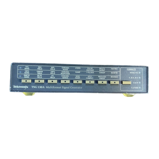
Tektronix TSG130A Instruction Manual (330 pages)
Multiformat Signal Generator
Brand:
Tektronix
| Category:
Laboratory Equipment
| Size: 6 MB
Table of Contents
List of Figures
7
Table of Contents
7
Figure 3-3: y Channel - 75% Bars
8
Figure 3-4: C Channel - 75% Bars
9
Figure 3-8: C Channel - 100% Bars
9
Figure 3-9: y Channel - SMPTE Bars
11
Figure 3-10: C Channel - SMPTE Bars
11
Figure 3-19: y Channel - Blue Field
12
Figure 3-20: C Channel - Blue Field
12
Figure 3-21: y Channel - Green Field
12
List of Tables
15
Figure 1-1: TSG130A Front Panel
23
Figure 1-2: TSG130A Rear Panel
23
For Option
24
Table 1-2: Available Outputs for Standard TSG130A in Various
25
Table 1-3: Available Outputs for TSG130A Option 2
26
Table 1-4: TSG130A Test Signal Summary, for Option 01 and 01/02 Mll Signals
26
Table 1-5: Available Outputs for TSG130A Option 01
27
Table 1-6: Available Outputs for TSG130A, Opt 01/02
28
Table 1-7: TSG130A Test Signal Summary, for Option 2J Signals
28
Table 1-8: TSG130A Rear Panel Output, in Various Formats
29
Table 1-9: TSG130A Test Signal Summary, for Option 03 Signals
29
Table 1-10: TSG130A Rear Panel Output, in Various Formats, for Option 03
30
Table 1-11: TSG130A Test Signal Summary, for Option 04 Mll
31
Table 1-12: TSG130A Rear Panel Outputs, in Various Formats
31
Table 1-13: TSG130A Test Signal Summary, for Option 05
32
Table 1-14: Available Outputs for TSG130A, Opt 05
33
Table 1-15: TSG130A Option Signal Comparison
34
Table 1-16: Power Cord Identification
36
Figure 2-1: TSG130A Front Panel
39
Figure 2-2: Determining the Signal Selected
40
Figure 2-3: TSG130A Rear Panel
41
Figure 2-4: NTSC/YC Format Signal Locations
43
Table 2-1: NTSC/YC Format Available Signals
43
Figure 2-5: NTSC/YC Format Rear Panel Signal Locations
44
Figure 2-6: Y, B-Y, R-Y Format Signal Locations
44
Table 2-2: NTSC/YC Format Rear Panel Outputs
44
Table 2-3: Y, B-Y, R-Y Format Available Signals
44
Figure 2-7: Y, B-Y, R-Y Format Rear Panel Signal Locations
45
Figure 2-8: GBR Format Signal Locations
45
Table 2-4: Y, B-Y, R-Y Format Rear Panel Outputs
45
Table 2-5: GBR Format Available Signals
45
Figure 2-10: Y-CTDM Format Signal Locations
46
Figure 2-9: GBR Format Rear Panel Signal Locations
46
Table 2-6: GBR Format Rear Panel Outputs
46
Table 2-7: Y-CTDM Format Available Signals
46
Figure 2-11: Y-CTDM Format Rear Panel Signal Locations
47
Table 2-8: Y-CTDM Format Rear Panel Outputs
47
Table 3-1: Certifications and Compliances
52
Table 3-2: General Test Signal Characteristics
53
Table 3-3: General NTSC/YC Signal Characteristics (NTSC/YC Formats Only)
54
Table 3-4: NTSC/YC Test Signal Definitions
55
Figure 3-1: Options 01/02, 02, and 03 Black Burst Output
71
Figure 3-2: Option 2J Black Burst Output
71
Figure 3-5: y Channel - 75% Red (same as Red Field)
73
Figure 3-6: C Channel - 75% Red (same as Red Field)
73
Figure 3-7: y Channel - 100% Bars
74
Figure 3-11: y Channel - SMPTE Reverse Blue Bars
76
Figure 3-12: C Channel - SMPTE Reverse Blue Bars
76
Figure 3-13: y Channel - SMPTE Bars (IYQB)
77
Figure 3-14: C Channel - SMPTE Bars (IYQB)
77
Figure 3-15: y Channel - NTC7 Composite
78
Figure 3-16: C Channel - NTC7 Composite
78
Figure 3-17: y Channel - Chroma Frequency Response
79
Figure 3-18: C Channel - Chroma Frequency Response
79
Advertisement
Advertisement
Related Products
Tektronix TSG1001
Tektronix TSG 120
Tektronix TSG1
Tektronix TSG 131A
Tektronix TSG4102A
Tektronix TSG4106A
Tektronix TSG 601
Tektronix TSG4100A Series
Tektronix TSG4100A-RM1
Tektronix TSG4100A-RM2
Tektronix Categories
Test Equipment
Measuring Instruments
Amplifier
Portable Generator
Printer
More Tektronix Manuals
Login
Sign In
OR
Sign in with Facebook
Sign in with Google
Upload manual
Upload from disk
Upload from URL