
Related Manuals for Droplet Dual-Column CCN


Summary of Contents for Droplet Dual-Column CCN
- Page 1 Dual-Column Cloud Condensation Nuclei Counter Operator Manual for Dual-Column CCN DOC-0128 Revision F 2400 Trade Centre Avenue Longmont, CO 80503 USA...
- Page 2 Droplet Measurement Technologies. Although every precaution has been taken in the preparation of this document, Droplet Measurement Technologies assumes no responsibility for errors or omissions. Neither is any liability assumed for damages resulting from the use of the information contained herein.
- Page 3 Great care must be taken to avoid exposure to the laser, Do not remove protective barriers. CAUTION: Use of control or adjustments or performance of procedures other than specified in this manual may result in hazardous radiation exposure. DOC-0128 Rev F © 2017 DROPLET MEASUREMENT TECHNOLOGIES...
-
Page 4: Table Of Contents
C O N T E N T S Setting up the Dual-Column CCN (CCN-200) ............8 Unpacking ..........................8 Connecting the Instrument Components ................9 USB Memory Stick ....................... 11 Setting the Flow and Humidifying the CCN-200 ..............12 Checking out the CCN-200 ....................14 1.5.1... - Page 5 Appendix F: CCN-200 Aircraft Inlet ................108 Appendix G: Sheath Flow Filter Testing and Replacement..........109 18.0 Appendix H: CCN Accessories ................. 110 18.1 Spares and Consumable Supplies ..................110 Appendix I: Revisions to Manual ................. 111 DOC-0128 Rev F © 2017 DROPLET MEASUREMENT TECHNOLOGIES...
- Page 6 Table 1: Dual Column CCN Fuse Listing ................52 Figure 33: Nafion Insertion .................... 54 Figure 34: Typical Healthy Membrane ................54 Figure 35: Typical Bad Membrane Note Kinks and Flat spots .......... 54 DOC-0128 Rev F © 2017 DROPLET MEASUREMENT TECHNOLOGIES...
- Page 7 Figure 65: Using Playback Controls for Zooming ............95 Figure 66: Selectable Chart Control Panel ..............96 Figure 67: Shutdown Button ..................99 Figure 68: Percentage of CCN Counted vs. Particle Concentration for Different SS% ..105 DOC-0128 Rev F © 2017 DROPLET MEASUREMENT TECHNOLOGIES...
-
Page 8: Setting Up The Dual-Column Ccn (Ccn-200)
Setting up the Dual-Column CCN (CCN-200) Several steps are required for initial CCN-200 set-up: • Unpacking and mounting the instrument Connecting CCN components such as the power cables, supply and drain bottles, and touch • screen monitor • Setting the flow and humidifying the instrument (humidification can take up to 12 hours and must be performed every time the CCN is dry when started) •... -
Page 9: Connecting The Instrument Components
4) Fill supply bottle with distilled or deionized water and set it in the front of the bottle tray. 5) For airborne applications, install the bottle hold-down clamp. Figure 2 shows the hold-down clamp on a CCN-100 instrument; the clamp is identical on the CCN-200. DOC-0128 Rev F © 2017 DROPLET MEASUREMENT TECHNOLOGIES... -
Page 10: Figure 2: Bottle Hold-Down Clamp
8) Remove plugs from inlet and outlet fitting on the side of the unit. 9) Proceed to the following section. DOC-0128 Rev F © 2017 DROPLET MEASUREMENT TECHNOLOGIES... -
Page 11: Usb Memory Stick
White papers describing the theory behind the CCN design • • A copy of the CCN-200 manual • Detailed spreadsheets for use in instrument calibration LabVIEW software programs used to operate the CCN-200 • Figure 3: USB Memory Stick DOC-0128 Rev F © 2017 DROPLET MEASUREMENT TECHNOLOGIES... -
Page 12: Setting The Flow And Humidifying The Ccn-200
5. The flow ratio between the sheath and sample flow is displayed directly in the center window. Adjust the green knobs on the sheath flow metering valves (See Figure 26) until these ratios read 10.0 +/- 0.3. DOC-0128 Rev F © 2017 DROPLET MEASUREMENT TECHNOLOGIES... -
Page 13: Figure 5: Drying System Time Switch (In Center, Circled)
2-second position will speed the removal of water vapor. (The switch should be returned to the 16- second position after the fog has dissipated.) For more details on the OPC drying system, see section 10.1. DOC-0128 Rev F © 2017 DROPLET MEASUREMENT TECHNOLOGIES... -
Page 14: Checking Out The Ccn-200
1) Install the filter on the inlet while the instrument is running. 2) Wait 15 minutes for system to clean out. Counts should now be less than five per second. DOC-0128 Rev F © 2017 DROPLET MEASUREMENT TECHNOLOGIES... -
Page 15: Counting Test
6) Repeat the above procedure for both columns. The concentrations for the two columns should not differ by more than 15% for the same supersaturation setting and sample source. DOC-0128 Rev F © 2017 DROPLET MEASUREMENT TECHNOLOGIES... -
Page 16: Leak Test (For Dual Ccns Installed In Pressurized Aircraft)
You can also close Windows first by turning off the computer and then turning off the power switch on the side of the unit when the screen goes blank. DOC-0128 Rev F © 2017 DROPLET MEASUREMENT TECHNOLOGIES... - Page 17 If additional water has entered the system, contact Droplet Measurement Technologies immediately. WARNING! The CCN Counter must be prepared for shipping by drying the column and draining the OPC.
-
Page 18: Installation
CCN-200. If problems occur when operating the CCN-200 in an aircraft environment, check the line voltage to 28 VDC supply. A 28 VDC aircraft cable with a filter is included and should be used for aircraft operation. DOC-0128 Rev F © 2017 DROPLET MEASUREMENT TECHNOLOGIES... -
Page 19: Product Description
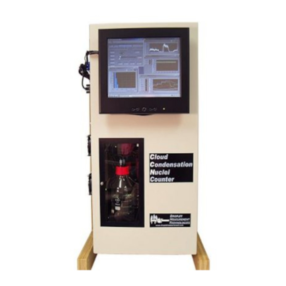
The CCN-200 (Figure 9) is based on the design of Dr. Greg Roberts of Scripps Institute of Oceanography. Dr. Athanasios Nenes of Georgia Institute of Technology did the CCN-200’s theoretical parameterization. The technology is patented, and Droplet Measurement Technologies possesses the exclusive license to manufacture the instrument. -
Page 20: Specifications
Replace sheath flow filter Recommended Service Annual cleaning and calibration at DMT service facility Front Panel Display Computer monitor Within each column, the supersaturation is constant. However, the two columns can maintain different supersaturation rates. DOC-0128 Rev F © 2017 DROPLET MEASUREMENT TECHNOLOGIES... - Page 21 For lab use (with frame): 50 kg / 110 lb • For aircraft use (without frame): 43.8 kg / 96.5 lb Environmental Operating Conditions: Temp 5 – 40°C (41 – 104 °F) 0 – 100% RH non-condensing DOC-0128 Rev F © 2017 DROPLET MEASUREMENT TECHNOLOGIES...
-
Page 22: Operating Limits
B. The temperature at point C is lower than at point B, however, which means that there is more water vapor (corresponding to the saturation vapor pressure at point B) than thermodynamically allowed. Figure 10:Supersaturation Being Generated in the CCN Column DOC-0128 Rev F © 2017 DROPLET MEASUREMENT TECHNOLOGIES... -
Page 23: Details Of Ccn Design
Activated droplet counting is done with two Optical Particle Counters (OPCs), one for each column. The OPC has been specially designed for the CCN and uses side-scattering technology for the particle sizing. -
Page 24: Instrument Components
The picture on the inside of the manual’s front cover shows the front view of the CCN-200 with important components labeled. (Figure 11). Figure 11: Side View of CCN with Important Components Labeled DOC-0128 Rev F © 2017 DROPLET MEASUREMENT TECHNOLOGIES... -
Page 25: Figure 12: Traps And Pumps
Operator Manual, Dual-Column Cloud Condensation Nuclei Counter (CCN-200) Figure 12 , Figure 13, Figure 14, and Figure 15 show close-ups of some of the components that are not easily visible in the main photo. Figure 12: Traps and Pumps DOC-0128 Rev F © 2017 DROPLET MEASUREMENT TECHNOLOGIES... -
Page 26: Figure 13: Tec Current Controllers
Figure 13: TEC Current Controllers DOC-0128 Rev F © 2017 DROPLET MEASUREMENT TECHNOLOGIES... -
Page 27: Figure 14: Sheath Flow Filters And Frits
Operator Manual, Dual-Column Cloud Condensation Nuclei Counter (CCN-200) Figure 14: Sheath Flow Filters and Frits Proportional Valves Figure 15: Proportional Valves DOC-0128 Rev F © 2017 DROPLET MEASUREMENT TECHNOLOGIES... -
Page 28: Air And Water Flows
4.4 Air and Water Flows Diagrams of the air and water flows for the two CNN-200 columns (Figure 16)(Figure 17) Figure 16: Air and Water Flow for Column A DOC-0128 Rev F © 2017 DROPLET MEASUREMENT TECHNOLOGIES... -
Page 29: Figure 17: Air And Water Flow For Column B
Operator Manual, Dual-Column Cloud Condensation Nuclei Counter (CCN-200) Figure 17: Air and Water Flow for Column B DOC-0128 Rev F © 2017 DROPLET MEASUREMENT TECHNOLOGIES... -
Page 30: Sample And Sheath Air Flows
Do not allow unit to run when supply water bottle is empty or unit may not function properly when water is added. All index numbers given are for Column A diagram. The Column B diagram is very similar. DOC-0128 Rev F © 2017 DROPLET MEASUREMENT TECHNOLOGIES... - Page 31 CCN-200 measurements, the switch can be set in the 16 second position. If the OPC has fogged, switch to the 2-second position to quickly remove the water vapor. Switch back to 16 seconds for normal operation. DOC-0128 Rev F © 2017 DROPLET MEASUREMENT TECHNOLOGIES...
-
Page 32: Power And Communication Connections
Figure 18: Location of Power, Communications, Sample and Exhaust Connections The MAIN POWER switch is a 30-Amp circuit breaker for protection of the CCN=-200 instrument. The pilot light indicates instrument power ON. The data communication connectors are as follows: DOC-0128 Rev F © 2017 DROPLET MEASUREMENT TECHNOLOGIES... - Page 33 Finally, a leak check should be performed on the CCN-200 before operating in a pressurized cabin. Leaks that were not apparent prior to pressurization may become problematic in a pressurized cabin. Note: Both A and B Columns are controlled by the switch on “A” printed circuit board DOC-0128 Rev F © 2017 DROPLET MEASUREMENT TECHNOLOGIES...
-
Page 34: Printed Circuit Boards
Power is supplied to inlet heater Power is supplied to OPC heater TEC Relay is ON 28 V power is present in unit 5 V power supply on Power Supply Board is present DOC-0128 Rev F © 2017 DROPLET MEASUREMENT TECHNOLOGIES... -
Page 35: Figure 20: Cdpe Board. D1, D2, And D3
Figure 20: CDPE Board. D1, D2, and D3. NOTE: D1, D2, and D3 are lit all the time when there is power supplied to the instrument. These boards are installed behind other boards and are not visible DOC-0128 Rev F © 2017 DROPLET MEASUREMENT TECHNOLOGIES... -
Page 36: Figure 21: Power Supply Boards For Tec Current Control Module, With Led Circled
Figure 21 depicts the board for Column A, with the LED indicator circled. Figure 21: Power Supply Boards for TEC Current Control Module, with LED Circled Figure 22 shows the OPC board. Figure 22: OPC Board DOC-0128 Rev F © 2017 DROPLET MEASUREMENT TECHNOLOGIES... -
Page 37: Ccn Maintenance
Operator Manual, Dual-Column Cloud Condensation Nuclei Counter (CCN-200) CCN Maintenance Droplet Measurement recommends the following service and maintenance schedule for the Dual Column CCN. The maintenance schedule is based on the continuous operation of the instrument and may need to be modified for other operating conditions. -
Page 38: Every Year
These can also be replaced when their estimated lifetime expires. The pump diaphragm lifetime is approximately 4000 hours, while the pump motor lifetime is approximately 8000 hours. DOC-0128 Rev F © 2017 DROPLET MEASUREMENT TECHNOLOGIES... -
Page 39: Calibration Procedures
The CN Counter is used as a reference instrument. It will count 100% of all the particles that are fed into it from the DMA. The ratio of the number of particles the CCN could count if they activated can now be determined. DOC-0128 Rev F © 2017 DROPLET MEASUREMENT TECHNOLOGIES... -
Page 40: Ss% Calibration Procedure
Sheath:Sample Flow Ratio: 10:1 3-Degree Activation Curve (500 Vccm, 840 mb) 90 100 110 120 130 140 150 160 170 180 190 Dry Particle Diameter (nm) Figure 24: Activation Curve Used in SS% Calibration DOC-0128 Rev F © 2017 DROPLET MEASUREMENT TECHNOLOGIES... -
Page 41: Flow Calibrations
Volumetric displacement flow meter (the range should be from 10-1000 Vccm) • • USB stick that accompanies the CCN (this contains initial factory calibration data to be used as a reference, as well as a spreadsheet to run the regression analysis) DOC-0128 Rev F © 2017 DROPLET MEASUREMENT TECHNOLOGIES... -
Page 42: Flow Calibrations Procedure
6) Using the Valve Set M (V) field, adjust the valve voltage until the sample flow as measured on the external flow meter (not on the computer display) is in the range of 20-75 vccm. DOC-0128 Rev F © 2017 DROPLET MEASUREMENT TECHNOLOGIES... -
Page 43: Figure 27: Entering Values In The Calibration Spreadsheet For Regression Analysis
(You can record it for informational purposes, if you want to remember which settings are used to achieve specific flow rates.) Figure 27: Entering Values in the Calibration Spreadsheet for Regression Analysis DOC-0128 Rev F © 2017 DROPLET MEASUREMENT TECHNOLOGIES... -
Page 44: Figure 28: Sheath Flow Calibration Spreadsheet
1 in Figure 28. Record the displayed sample flow in the “sample” column (arrow 2). The spreadsheet will auto-calculate sheath flow (sheath flow = total flow – sample flow). Figure 28: Sheath Flow Calibration Spreadsheet DOC-0128 Rev F © 2017 DROPLET MEASUREMENT TECHNOLOGIES... -
Page 45: Pressure Calibration
4. Replace the cover on the CCN-200 instrument. 8.4 OPC Calibration 8.4.1 Recommended Calibration Equipment • Aerosol generator system for nebulizing polystyrene latex (PSL) particles, such as the DMT aerosol generator. • PSL calibration particles, 2.0 micron. DOC-0128 Rev F © 2017 DROPLET MEASUREMENT TECHNOLOGIES... -
Page 46: Opc Calibration Procedure
5. Note the bin where the calibration particles are measured. A good calibration exists if the particles are in the proper bin or slightly high. If the particles are in a lower size bin, the OPC could be dirty and will need cleaning and recalibration. Contact Droplet Measurement Technologies. -
Page 47: Figure 30: Column A's Beam Dump And Set Screws. Column B Has An Identical Opc
Insert the tube on the end of an inert dusting gas (such as Tech-Spray, Envi-ro-tech 1671 Duster) about halfway into the Beam Dump opening. Figure 32 contains an exploded view of the OPC that may be useful when following these steps. DOC-0128 Rev F © 2017 DROPLET MEASUREMENT TECHNOLOGIES... -
Page 48: Figure 31: Air Drying Opc With Canned Air
Figure 31: Air Drying OPC with Canned Air NOTE: image is a CNN-100, but the procedure is identical for the CCN-200 Reinstall the Beam Dump, ensuring that the O-ring is in place and the orientation is correct. DOC-0128 Rev F © 2017 DROPLET MEASUREMENT TECHNOLOGIES... -
Page 49: Figure 32: Opc Assembly, Exploded View
Operator Manual, Dual-Column Cloud Condensation Nuclei Counter (CCN-200) Figure 32: OPC Assembly, Exploded View DOC-0128 Rev F © 2017 DROPLET MEASUREMENT TECHNOLOGIES... -
Page 50: Troubleshooting
“Column Temps Stabilized No action required. If temperatures are too far from Temperatures stabilizing at Status” light is yellow. set point, Temperature Control Status will alarm. slightly more than 0.3 degrees from set point. DOC-0128 Rev F © 2017 DROPLET MEASUREMENT TECHNOLOGIES... - Page 51 DMT for further information. 4. If a zone is found to have a bad TEC element, contact DMT. Do not try to bypass the TEC as can be done with the CCN-100. DOC-0128 Rev F © 2017 DROPLET MEASUREMENT TECHNOLOGIES...
- Page 52 Touch screen 28 VDC spare 28 VDC spare power circuit circuit Nafion heater Nafion heater Inlet heater Inlet heater OPC heater OPC heater Table 1: Dual Column CCN Fuse Listing DOC-0128 Rev F © 2017 DROPLET MEASUREMENT TECHNOLOGIES...
- Page 53 Be careful not to let the Nafion membrane get pushed inside the block on both ends, as one end needs to be exposed for removal. Remove the o-rings on the top and bottom. DOC-0128 Rev F © 2017 DROPLET MEASUREMENT TECHNOLOGIES...
-
Page 54: Figure 33: Nafion Insertion
Turn on supply pump to wet membrane. If the problem persists, contact DMT. Figure 33: Nafion Insertion Figure 34: Typical Healthy Membrane Figure 35: Typical Bad Membrane Note Kinks and Flat spots DOC-0128 Rev F © 2017 DROPLET MEASUREMENT TECHNOLOGIES... - Page 55 DMA. isn’t properly Swap out suspect OPC with a known good OPC. calibrated Contact DMT for details. CCN unit itself isn’t properly Return unit for factory calibration. calibrated DOC-0128 Rev F © 2017 DROPLET MEASUREMENT TECHNOLOGIES...
- Page 56 (PLUM-0185 provided in start-up kit) installed. unnoticeable. Possible leak. Leak test unit; see section 0. Possible bad filter Replace filter. Leak in unit. Perform the leak test described in section 0. Leak is suspected. DOC-0128 Rev F © 2017 DROPLET MEASUREMENT TECHNOLOGIES...
-
Page 57: Preparing The Ccn For Shipping
Note that any time the instrument is dried out, it must be rehumidified before you operate it again. See section 1.4 for details. Note: Most leaks are operator induced. Bottle caps need to be tightened fully to seal properly. DOC-0128 Rev F © 2017 DROPLET MEASUREMENT TECHNOLOGIES... - Page 58 If DUAL COLUMN CCN is returned to DMT, NOT on a DUAL COLUMN CCN pallet: You will be charged for a new DUAL COLUMN CCN pallet COST: one hundred dollars ($100.00) per pallet DOC-0128 Rev F © 2017 DROPLET MEASUREMENT TECHNOLOGIES...
-
Page 59: Part Ii: Ccn-200 Software
(PADS) module for the CCN-200. This module allows integrated use of the CCN-200 with other DMT instruments. Screen shots in this document are taken from versions 5.0.3 (Single CNN.exe), 5.0.1 (SS Settings Config Editor.vi and CCN Calibration Config Editor.vi), and 5.0.2 (Single CCN Playback.exe). DOC-0128 Rev F © 2017 DROPLET MEASUREMENT TECHNOLOGIES... -
Page 60: Dual Ccn.exe (Main Program)
“Column Controls.” In the upper right of the display are fields showing the date, time, and other common indicators. These are described in section 12.1. DOC-0128 Rev F © 2017 DROPLET MEASUREMENT TECHNOLOGIES... -
Page 61: Common Indicators (Appear On All Ccn-200 Tabs)
The column controls appear on the left side of the Dual CCN window. As stated above, the controls and indicators for Column A appear above those for Column B. The Column A and Column B tabs are identical except for the very last tab. The tabs are discussed below. DOC-0128 Rev F © 2017 DROPLET MEASUREMENT TECHNOLOGIES... -
Page 62: Ss (Supersaturation) Settings Tab
After 4 – 12 hours, the unit will reset itself to normal mode. Dry Shut Down should only be selected when the unit needs to be totally dried out prior to shipping. DOC-0128 Rev F © 2017 DROPLET MEASUREMENT TECHNOLOGIES... - Page 63 In Manual SS mode, the Manual Input Selection radio button (Figure 40, bottom middle) specifies whether the user will enter Delta T Set (C) or enter the supersaturation directly. DOC-0128 Rev F © 2017 DROPLET MEASUREMENT TECHNOLOGIES...
-
Page 64: Figure 40: Supersaturation (Ss) Settings Tab Display In Manual Ss Mode
The default value for Delta T Set (C) is the last setting the program was previously running when Auto SS mode is switched off. Note that while the SS Table remains visible during Manual SS mode, the program is not using it. DOC-0128 Rev F © 2017 DROPLET MEASUREMENT TECHNOLOGIES... -
Page 65: Temps Tab (Temperatures)
Changes apply to the current session only. To change the permanent default values for these differentials, do so from the CNN Calibration Editor program; see section 14.0. Inlet Heater, Naf. Heater and OPC Heater indicators are illuminated when respective heater is ON. DOC-0128 Rev F © 2017 DROPLET MEASUREMENT TECHNOLOGIES... - Page 66 Current SS and the temperature gradient slope and intercept coefficients. (See sections 12.6.1.2 and 14.0.) In Manual SS mode, Delta T(C) becomes a control and can be set through the Temps tab or • through the serial port. DOC-0128 Rev F © 2017 DROPLET MEASUREMENT TECHNOLOGIES...
- Page 67 Sample Temp Setpoint is a temporary variable used by the software. It is equal to whatever TSample was when conditions 2 or 3 were last true. %TG is a temperature-gradient adjustment factor. For details, see section 14.0. DOC-0128 Rev F © 2017 DROPLET MEASUREMENT TECHNOLOGIES...
-
Page 68: Flows Tab
Valve Set M (V) controls the voltage supplied to the proportional control valve. This parameter is only used when the instrument is in manual override mode. Sample Flow (Vccm) displays the measured sample flow. Sheath Flow (Vccm) displays the measured sheath flow. DOC-0128 Rev F © 2017 DROPLET MEASUREMENT TECHNOLOGIES... - Page 69 High is useful if water supply has run dry or if it is necessary to wet the column quickly. Liquid Supply Pump switches the supply pump ON/OFF. The two drain pumps—i.e., the column and chiller pumps—run continuously. DOC-0128 Rev F © 2017 DROPLET MEASUREMENT TECHNOLOGIES...
-
Page 70: Opc Tab (Optical Particle Counter)
To the left of the Bin Setting table is the index field, which displays the number of the first bin setting displayed in the array. In Figure 44, for instance, the first bin setting displayed corresponds to the first row (index 0) in the SS Table. DOC-0128 Rev F © 2017 DROPLET MEASUREMENT TECHNOLOGIES... - Page 71 Laser current alarm level displays the level at which an alert will be given when the laser draws this amount or more of current. Such an alert indicates the laser is nearing the end of its life. DOC-0128 Rev F © 2017 DROPLET MEASUREMENT TECHNOLOGIES...
-
Page 72: Monitor Tab (Alarm Monitoring)
This sum is then made negative if any alarms (i.e., not just alerts) have been triggered. More information is given below about specific status fields, their corresponding alert codes, and whether the system ultimately generates an alarm for this problem. DOC-0128 Rev F © 2017 DROPLET MEASUREMENT TECHNOLOGIES... - Page 73 2 number, the sum of alarm codes will always indicate a unique set of issues.) A negative alarm code indicates problems severe enough that the instrument has gone into safe mode. DOC-0128 Rev F © 2017 DROPLET MEASUREMENT TECHNOLOGIES...
-
Page 74: Prog Control Tab
WARNING! It is important to use the Shutdown button when shutting down the instrument; this will ensure that the pumps are shut off in order and the files are saved properly. DOC-0128 Rev F © 2017 DROPLET MEASUREMENT TECHNOLOGIES... -
Page 75: Chart Tab
Figure 48 shows the Chart tab before a session has started. No data is available yet, but the chart display is set to show up to four hours of data once it becomes available. DOC-0128 Rev F © 2017 DROPLET MEASUREMENT TECHNOLOGIES... -
Page 76: Histograms
Figure 50 shows the Flow chart for Column A, with the legend in the upper-right corner. Note that Flows charts display Sample Flow, Sheath Flow and Total Flow. Figure 50: Flow A Chart DOC-0128 Rev F © 2017 DROPLET MEASUREMENT TECHNOLOGIES... -
Page 77: Serial Output Tab
A carriage return separates the first set of data from the second, which starts with a “C” and continues with the output channels specified in the column on the right in Figure 51. DOC-0128 Rev F © 2017 DROPLET MEASUREMENT TECHNOLOGIES... -
Page 78: Dmt Tab (Accesses Service Tabs)
1) Click just below the text window in the middle of the screen. 2) A white text box should appear (Figure 53). 3) Type in the password Service. Figure 53: Text Box for Entering Password to Access DMT-Service Tab DOC-0128 Rev F © 2017 DROPLET MEASUREMENT TECHNOLOGIES... -
Page 79: Figure 54: Dmt Service Tab - Pid Sub-Tab
Figure 54: DMT Service Tab – PID Sub-Tab The proportional valve voltage determines how open or closed the proportional valve will be, which in turn regulates total sample flow. DOC-0128 Rev F © 2017 DROPLET MEASUREMENT TECHNOLOGIES... - Page 80 (s) specifies the interval in seconds at which the PID routine is called. If this parameter is equal or less than zero, the PID routine estimates the time it was last called using an internal timer. Reinitialize (F) sets the PID parameters back to their DMT-supplied default values. DOC-0128 Rev F © 2017 DROPLET MEASUREMENT TECHNOLOGIES...
-
Page 81: Figure 55: Dmt Service Tab - Offset & Gains Sub-Tab
This tab allows users to enter the slope and intercept of the equation to convert SS% to Temperature Gradient. SS to TG (Temperature Gradient) stores the slope coefficient, while SS offset stores the offset. Refer to section 8.1 for the complete SS% calibration procedure. DOC-0128 Rev F © 2017 DROPLET MEASUREMENT TECHNOLOGIES... -
Page 82: Figure 56: Dmt Service Tab - Flow Calib. Sub-Tab
Refer to section 8.2 for the complete flow calibration procedure. The Supply Pump and Drain Pump indicators blink during normal operation when the pumps are on. DOC-0128 Rev F © 2017 DROPLET MEASUREMENT TECHNOLOGIES... -
Page 83: Figure 57: Dmt Service Tab - Error Sub-Tab
The service mode is also exited upon closing of the VI or rebooting the computer. DOC-0128 Rev F © 2017 DROPLET MEASUREMENT TECHNOLOGIES... -
Page 84: Program Input Files
Both of these files are in the C:\ directory, but they should not be modified directly. Instead, use the program SS Settings Config Editor.exe to modify CCN_SS_Settings.ini and CCN Calibration Editor.exe to modify CCN_Calibration.ini. DOC-0128 Rev F © 2017 DROPLET MEASUREMENT TECHNOLOGIES... -
Page 85: Program Output Data
N-1 data protocol. Connecting this port to another computer requires the use of a null modem between the computers so that pins 2 and 3 are swapped. Users can select three options for serial stream output: no output, normal output, or user-defined output. DOC-0128 Rev F © 2017 DROPLET MEASUREMENT TECHNOLOGIES... - Page 86 1st Stage Mon. B Valve Set B Alarm Code * Bin Array A and Bin Array B are arrays containing Bin 1, Bin 2, Bin 3… Bin 30 counts for Column A and B, respectively. DOC-0128 Rev F © 2017 DROPLET MEASUREMENT TECHNOLOGIES...
-
Page 87: Output Files
= the two digits for seconds • Example: May 6, 2004 at 4:18:27 would be 040506041827. This convention lists files created sequentially from start time, which provides an easy way to locate specific files. DOC-0128 Rev F © 2017 DROPLET MEASUREMENT TECHNOLOGIES... - Page 88 Alarm Sum Sheath Flow A Nafion Set B As with serial-stream data, all Bin channels store raw particle counts rather than concentration. For definitions of these channels, see the Glossary in Appendix A. DOC-0128 Rev F © 2017 DROPLET MEASUREMENT TECHNOLOGIES...
-
Page 89: Ss Settings Config Editor
The tables allow the following preconfigured settings to be loaded into the operating program: • Supersaturation rate Duration in minutes for the supersaturation setting • DOC-0128 Rev F © 2017 DROPLET MEASUREMENT TECHNOLOGIES... -
Page 90: Ccn Calibration Editor.exe
While the DMT Service tab allows the user to modify many of the parameters available on the CCN Calibration Editor.exe, the Calibration Editor program provides access to some unique parameters as well. DOC-0128 Rev F © 2017 DROPLET MEASUREMENT TECHNOLOGIES... -
Page 91: Standard Screen
0. In this way the values on the Flows tab will read out in volts. A new set of calibration coefficients can then be derived and entered into the program. DOC-0128 Rev F © 2017 DROPLET MEASUREMENT TECHNOLOGIES... -
Page 92: Figure 61: Ccn Calibration Editor.exe With Dmt Tabs
Additional parameters can be viewed by clicking on the Show DMT Settings button, which is visible in the upper left of the screen. Pressing this button brings up the window shown on the right-hand side of Figure 61. Figure 61: CCN Calibration Editor.exe with DMT Tabs DOC-0128 Rev F © 2017 DROPLET MEASUREMENT TECHNOLOGIES... - Page 93 P, I, D, and Flow Avg # are used in the PID control loop. dt (s) specifies the interval in seconds at which the PID routine is called. If this parameter is equal or less than zero, the PID routine estimates the time it was last called using an internal timer. DOC-0128 Rev F © 2017 DROPLET MEASUREMENT TECHNOLOGIES...
-
Page 94: Dual Ccn Playback.exe
Playback button is illuminated. To stop playback, click on the STOP button. Note: The software currently mislabels the y-axis for the number concentration chart. Units should be in particles/cc, not ccm. This bug will be fixed in an upcoming version of the program. DOC-0128 Rev F © 2017 DROPLET MEASUREMENT TECHNOLOGIES... -
Page 95: Changing The Current Time
The controls that show the start and end of displayed data can also be used for zooming in on the data. To do this, move the two controls closer to each other, as shown in Figure 65. Figure 65: Using Playback Controls for Zooming DOC-0128 Rev F © 2017 DROPLET MEASUREMENT TECHNOLOGIES... -
Page 96: Chart Options (For Dual Ccn.exe And Ccn Playback.exe Programs)
Unless you specify otherwise, output files will be saved in the time- and-date-specific output file directory for the current session. Clear Graph - This erases the currently displayed data points from the graph. DOC-0128 Rev F © 2017 DROPLET MEASUREMENT TECHNOLOGIES... -
Page 97: Remote Operation Of Ccn Programs Through Remote Desktop
Computer, and then clicking Properties. 2. Under Advance System Settings, Computer name, domain, and workgroup settings, you can find your computer name, and its full computer name if your computer is on a domain. DOC-0128 Rev F © 2017 DROPLET MEASUREMENT TECHNOLOGIES... - Page 98 After right- clicking to paste the files, it may take up to a minute for the program to respond. DOC-0128 Rev F © 2017 DROPLET MEASUREMENT TECHNOLOGIES...
-
Page 99: Shutting Down The Ccn-200
Control tab and press “shutdown” (Figure 67. This will properly shut down the software. Figure 67: Shutdown Button Next, close Windows by turning off the computer through Windows. Then turn off the power switch on the side of the unit when the screen goes blank. DOC-0128 Rev F © 2017 DROPLET MEASUREMENT TECHNOLOGIES... -
Page 100: Appendix A: Glossary
/min. The CCN Number Conc. readings include oversized particles but do not include particles in bins smaller than the Bin #. When CCN Number Conc falls below its threshold for a sustained period, the CCN-200 computer generates an alarm. 1 0 0 DOC-0128 Rev F © 2017 DROPLET MEASUREMENT TECHNOLOGIES... - Page 101 Down should only be selected when the unit needs to be totally dried out prior to shipping. Inlet Set (C): The set point temperature at the CCN-200 inlet manifold. Köhler Curve: A mathematical function representing the cloud-droplet formation process. Köhler curves are used to calibrate the CCN-200 and determine the relationship between temperature gradient and supersaturation.
- Page 102 Users can select among existing SS tables from the SS Tab, and they can create or modify available SS tables using the CCN-200 SS Config Editor program. 1 0 2 DOC-0128 Rev F © 2017 DROPLET MEASUREMENT TECHNOLOGIES...
- Page 103 Valve Set: The voltage setting for the proportional valve. This setting can be either computer- generated or manually defined by the user. Vccm: Volume cubic centimeters / minute. Vccm is a unit of flow. 1 0 3 DOC-0128 Rev F © 2017 DROPLET MEASUREMENT TECHNOLOGIES...
- Page 104 Zero-Count Test: A CCN-200 test performed by installing a filter that is known to be working well onto the CCN-200 inlet, so that no aerosol particles can enter. The zero-count test should result in a particle reading of 5/sec or less. 1 0 4 DOC-0128 Rev F © 2017 DROPLET MEASUREMENT TECHNOLOGIES...
-
Page 105: Appendix B: Relationship Between Ss%, Particle Concentration, And Percentage Of Ccn Counted
0.08%SS 0.12%SS 0.19%SS 0.33%SS 0.47%SS 0.61%SS 5000 10000 15000 20000 25000 30000 35000 Concentration Figure 68: Percentage of CCN Counted vs. Particle Concentration for Different SS% 1 0 5 DOC-0128 Rev F © 2017 DROPLET MEASUREMENT TECHNOLOGIES... -
Page 106: Appendix C: Assy, Cable 28V Power
Appendix C: Assy, Cable 28V Power 1 0 6 DOC-0128 Rev F © 2017 DROPLET MEASUREMENT TECHNOLOGIES... -
Page 107: Appendix D: Dual Ccn Mounting Hole Locations
Operator Manual, Dual-Column Cloud Condensation Nuclei Counter (CCN-200) Appendix D: Dual CCN Mounting Hole Locations 1 0 7 DOC-0128 Rev F © 2017 DROPLET MEASUREMENT TECHNOLOGIES... -
Page 108: Appendix E: Further Resources
The CCN-200 Aircraft Inlet Schematic is similar to the schematic listed below, which is for the CCN- 100. On the CCN-200, there are two inlet ports rather than one. 1 0 8 DOC-0128 Rev F © 2017 DROPLET MEASUREMENT TECHNOLOGIES... -
Page 109: Appendix G: Sheath Flow Filter Testing And Replacement
DMT will have a “tested” label on them. Please contact Duncan Axisa at Droplet Measurement Technologies if you have any questions or concerns, or if you need to order replacement filters. Email CCN-Info@dropletmeasurement.com; Phone: 303-440- 5576 EX. -
Page 110: Appendix H: Ccn Accessories
Spare Electronic Repair Kit replacement. Major items: • 1 Power supply PCB • 1 Control PCB • 1 OPC and OPC control electronics • 1 80 GB-hard drive preloaded with instrument calibration 1 1 0 DOC-0128 Rev F © 2017 DROPLET MEASUREMENT TECHNOLOGIES... -
Page 111: Appendix I: Revisions To Manual
1/24/14 Revised OPC Cleaning Procedure 8.4.3 7/10/17 Add Intel Atom N2600 (Win 7) to Specs, remove kits Update Verbiage, Font, spacing throughout. For 10/15/17 Consistency with the Single-column product. 1 1 1 DOC-0128 Rev F © 2017 DROPLET MEASUREMENT TECHNOLOGIES...
Need help?
Do you have a question about the Dual-Column CCN and is the answer not in the manual?
Questions and answers