Sign In
Upload
Manuals
Brands
Droplet Manuals
Measuring Instruments
Dual-Column CCN
Droplet Dual-Column CCN Manuals
Manuals and User Guides for Droplet Dual-Column CCN. We have
1
Droplet Dual-Column CCN manual available for free PDF download: Operator's Manual
Droplet Dual-Column CCN Operator's Manual (111 pages)
Brand:
Droplet
| Category:
Measuring Instruments
| Size: 8 MB
Table of Contents
Table of Contents
4
Setting up the Dual-Column CCN (CCN-200)
8
Unpacking
8
Figure 1: Dual CCN with Shipping Hood, Pallet and Fitted Case
8
Connecting the Instrument Components
9
Figure 2: Bottle Hold-Down Clamp
10
USB Memory Stick
11
Figure 3: USB Memory Stick
11
Setting the Flow and Humidifying the CCN-200
12
Figure 4: SS Tab with Dry Start up and Dry Shut down Buttons Active
12
Figure 5: Drying System Time Switch (in Center, Circled)
13
Checking out the CCN-200
14
Zero-Count Test
14
Figure 6: Green Status Light
14
Counting Test
15
Leak Test (for Dual Ccns Installed in Pressurized Aircraft)
16
Figure 7: Connecting Inlet a to Inlet B with Tubing
16
Installation
18
Mounting Considerations
18
Power Supply Considerations
18
Figure 8: Vents Connected to Bottle Caps (for Aircraft Operation)
18
Product Description
19
Introduction
19
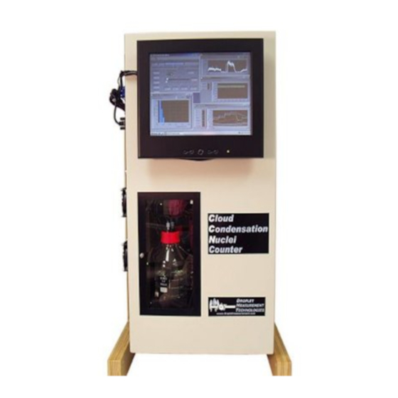
Figure 9: CCN-200 with Front-Mounted Touch Screen
19
Specifications
20
Operating Limits
22
Theory of Operation
22
How the CCN Generates Supersaturation
22
Figure 10:Supersaturation Being Generated in the CCN Column
22
Details of CCN Design
23
Instrument Components
24
Figure 11: Side View of CCN with Important Components Labeled
24
Figure 12: Traps and Pumps
25
Figure 13: TEC Current Controllers
26
Figure 14: Sheath Flow Filters and Frits
27
Figure 15: Proportional Valves
27
Air and Water Flows
28
Figure 16: Air and Water Flow for Column a
28
Figure 17: Air and Water Flow for Column B
29
Sample and Sheath Air Flows
30
How the System Maintains Pressure and Removes Excess Water
30
Power and Communication Connections
32
Figure 18: Location of Power, Communications, Sample and Exhaust Connections
32
Printed Circuit Boards
34
Figure 19: Power Supply and Controller Boards with Important Leds Identified
34
Figure 20: CDPE Board. D1, D2, and D3
35
Figure 21: Power Supply Boards for TEC Current Control Module, with LED Circled
36
Figure 22: OPC Board
36
CCN Maintenance
37
Every 2 Days / before Every Flight
37
Every Month
37
Every Three Months
37
Every Year
38
Pump Diaphragm and Motor Maintenance Requirements
38
Calibration Procedures
39
SS% Calibration
39
Recommended Calibration Equipment
39
Figure 23: Calibration Set-Up
39
SS% Calibration Procedure
40
Figure 24: Activation Curve Used in SS% Calibration
40
Flow Calibrations
41
Recommended Calibration Equipment
41
Figure 25: Temperature Gradient Curve for Different SS
41
Flow Calibrations Procedure
42
Figure 26: Sheath Flow Metering Valves
42
Figure 27: Entering Values in the Calibration Spreadsheet for Regression Analysis
43
Figure 28: Sheath Flow Calibration Spreadsheet
44
Pressure Calibration
45
Recommended Calibration Equipment
45
Pressure Calibration Procedure
45
OPC Calibration
45
OPC Calibration Procedure
46
OPC Cleaning Procedure
46
Figure 29: OPC 1St Stage Monitor Voltage
46
Figure 30: Column A's Beam Dump and Set Screws. Column B Has an Identical OPC
47
Figure 31: Air Drying OPC with Canned Air
48
Figure 32: OPC Assembly, Exploded View
49
Troubleshooting
50
Figure 33: Nafion Insertion
54
Figure 34: Typical Healthy Membrane
54
Figure 35: Typical Bad Membrane Note Kinks and Flat Spots
54
Preparing the CCN for Shipping
57
Dual Column CCN Drying Procedure Prior to Shipping
57
PART II: CCN-200 Software
59
Product Description
59
Introduction
59
Dual Ccn.exe (Main Program)
60
Figure 36: CCN-200 Window Quadrants
60
Common Indicators (Appear on All CCN-200 Tabs)
61
Column Controls
61
Figure 37: Indicators Visible on All CCN-200 Tabs
61
SS (Supersaturation) Settings Tab
62
Figure 38: SS Settings Tab
62
Figure 39: Dry Start up and Dry Shut down Buttons
62
Figure 40: Supersaturation (SS) Settings Tab Display in Manual SS Mode
64
Figure 41: SS Tab in Manual SS Mode with Delta T Selected as Manual Input
64
Temps Tab (Temperatures)
65
Figure 42: Temperature Tab Screen Shows Temp Set Points and CCN Temperatures
65
Flows Tab
68
Figure 43: Flows Control Tab
68
OPC Tab (Optical Particle Counter)
70
Figure 44: Optical Particle Counter Tab
70
Monitor Tab (Alarm Monitoring)
72
Figure 45: Monitor Tab
72
Prog Control Tab
74
Figure 46: Prog Control Tab
74
Chart Tab
75
Figure 47: Watch Dog Light
75
Figure 48: Chart Tab
75
Histograms
76
Time-Series Charts
76
Figure 49: Histograms
76
Figure 50: Flow a Chart
76
Serial Output Tab
77
Figure 51: Serial Output Tab in "Normal" Mode
77
DMT Tab (Accesses Service Tabs)
78
Figure 52: DMT Service Tab
78
Figure 53: Text Box for Entering Password to Access DMT-Service Tab
78
Figure 54: DMT Service Tab - PID Sub-Tab
79
Figure 55: DMT Service Tab - Offset & Gains Sub-Tab
81
Figure 56: DMT Service Tab - Flow Calib. Sub-Tab
82
Figure 57: DMT Service Tab - Error Sub-Tab
83
Program Input Files
84
Figure 58: DMT Service Tab - Timing Sub-Tab
84
Program Output Data
85
Serial Stream
85
Output Files
87
SS Settings Config Editor
89
Figure 59: Program for Setting the Supersaturation Tables
89
CCN Calibration Editor.exe
90
Standard Screen
91
Figure 60: CCN Calibration Editor.exe
91
Figure 61: CCN Calibration Editor.exe with DMT Tabs
92
Dual CCN Playback.exe
94
Figure 62: CCN Data Playback
94
Changing the Current Time
95
Figure 63: Playback Speed Control
95
Figure 64: Playback Timing Controls
95
Figure 65: Using Playback Controls for Zooming
95
Chart Options (for Dual Ccn.exe and CCN Playback.exe Programs)
96
Selectable Chart Options
96
Figure 66: Selectable Chart Control Panel
96
Remote Operation of CCN Programs through Remote Desktop
97
Shutting down the CCN-200
99
Figure 67: Shutdown Button
99
Appendix A: Glossary
100
Appendix B: Relationship between SS%, Particle Concentration, and Percentage of CCN Counted
105
Figure 68: Percentage of CCN Counted Vs. Particle Concentration for Different SS
105
Appendix C: Assy, Cable 28V Power
106
Appendix D: Dual CCN Mounting Hole Locations
107
Appendix E: Further Resources
108
Appendix F: CCN-200 Aircraft Inlet
108
Appendix G: Sheath Flow Filter Testing and Replacement
109
Appendix H: CCN Accessories
110
Spares and Consumable Supplies
110
Appendix I: Revisions to Manual
111
Advertisement
Advertisement
Related Products
Droplet APEX 2Q
Droplet CAS-DPOL
Droplet CCN-200
Droplet CDP-2
Droplet SP2
Droplet SP2-D
Droplet SP2-XR
Droplet Categories
Measuring Instruments
Laboratory Equipment
Indoor Fireplace
Water System
More Droplet Manuals
Login
Sign In
OR
Sign in with Facebook
Sign in with Google
Upload manual
Upload from disk
Upload from URL