
Related Manuals for Droplet CDP-2


Summary of Contents for Droplet CDP-2
- Page 1 Cloud Droplet Probe (CDP-2) Operator Manual DOC-0343, Rev A Includes Documentation on Particle-by-Particle Feature 2400 Trade Centre Avenue Longmont, CO 80301-5727 USA...
- Page 2 Droplet Measurement Technologies, LLC. Although every precaution has been taken in the preparation of this document, Droplet Measurement Technologies, LLC. assumes no responsibility for errors or omissions. Neither is any liability assumed for damages resulting from the use of the information contained herein.
- Page 3 Manual, Cloud Droplet Probe (CDP-2) Laser Safety Information The CDP contains a class IIIB laser. AVOID DIRECT EXPOSURE TO THE BEAM. Observe laser safety precautions and wear appropriate laser safety glasses. Avoid placing reflective materials in the beam that could redirect the beam, including watch bands, rings or tools. STRICT OBSERVANCE OF THE FOLLOWING WARNING LABELS IS ADVISED. The following label is located on the CDP: I I I DOC-0343 Rev A © 2017 DROPLET MEASUREMENT TECHNOLOGIES...
-
Page 4: Table Of Contents
7.2 Instructions .......................... 20 Appendix A: Revisions to Manual ................... 2 3 Appendix B: Glass Bead to Water Droplet Conversion Table for CDP‐2s...... 2 4 Appendix C: CDP Alignment Response ................ 2 5 Appendix D: Communications between the PC and CDP .......... 3 0 Communications Parameters ...................... 30 Initiating Communications ...................... 32 Communications Commands ...................... 32 SETUP DATA Command ........................ 32 Definition of the Declared Parameters ................... 34 CDP Response to SETUP DATA Command .................. 34 DOC-0343 Rev A © 2017 DROPLET MEASUREMENT TECHNOLOGIES... - Page 5 Manual, Cloud Droplet Probe (CDP-2) SEND DATA Command ........................ 35 CDP Response to the SEND DATA Command .................. 35 Definitions of the Send Data Response parameters .............. 37 Response Data Packet Length and Transmission Rate .............. 38 CDP Housekeeping Channels ...................... 39 SEND PbP DATA Command ...................... 40 CDP Response to the SEND PbP DATA Command ................ 40 Response Data Packet Length and Transmission Rate .............. 41 Definitions of the SEND PbP DATA Response parameters ............ 42 Changing the Serial Interface Type .................... 42 Appendix E: Mounting Considerations ................ 43 Appendix F: DMT Instrument Locator—Operator Guide .......... 45 Purpose ............................ 45 Installation ............................ 45 Operation............................ 45 Appendix G: CDP‐2 Dimensional Drawing ............... 46 Appendix H: Threshold Table for CDP‐2 ................. 48 ...
- Page 6 Figure 20: 20‐m glass beads CDP severe misalignment .......... 2 8 Figure 21: 40‐m glass beads CDP aligned .............. 2 8 Figure 22: 40‐m glass beads CDP moderate misalignment .......... 2 9 Figure 23: 40‐m glass beads CDP severe misalignment .......... 2 9 Figure 24: 20‐m glass beads calibration overload ............ 3 0 Figure 28: CDP Mounting Information ................ 4 3 Figure 29: CDP Electronics Mounting ................ 4 4 Figure 30: Instrument Locator .................. 4 6 DOC-0343 Rev A © 2017 DROPLET MEASUREMENT TECHNOLOGIES...
- Page 7 Manual, Cloud Droplet Probe (CDP-2) L i s t o f T a b l e s Table 1: PC‐CDP Communications Parameters .............. 31 Table 2: Data Structures Used in CDP‐Host Computer Communications...... 31 Table 3: Setup Command – Data Packet ................ 33 Table 4: CDP Response to Setup Command – Data Packet. .......... 35 Table 5: Send Data Command – Data Packet .............. 35 Table 6: CDP Response to Send Data Command ‐‐ Data Packet ........ 37 Table 7: Conversion Equations for Analog‐to‐Digital Housekeeping Channels .... 39 ...
-
Page 8: Product Description
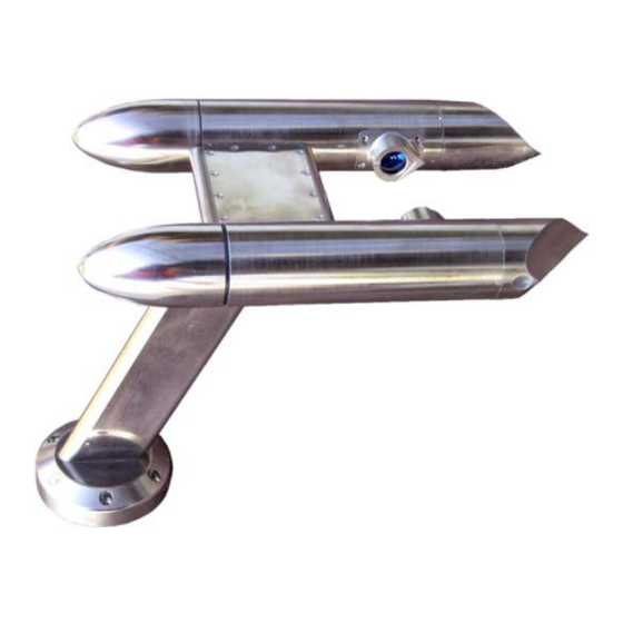
Product Description 1.1 Introduction The Cloud Droplet Probe (CDP) is designed to measure cloud droplet size distribution from 2 µm to 50 µm. The CDP and an appropriate data system can also calculate various other parameters including particle concentrations, effective diameter (ED), Median Volume Diameter (MVD), and Liquid Water Content (LWC). Droplet Measurement Technologies (DMT) has implemented state‐of‐the‐art electronics and optics that offer flexibility to the CDP user in a variety of applications. The miniaturized and streamlined housing allows use in a variety of ground‐based or airborne applications. The Particle Analysis and Display System (PADS) offers a graphical user interface at the host computer. PADS provides control of CDP measurement parameters while simultaneously displaying real‐time particle size distributions and derived parameters. All standard data interfaces are done via line drivers meeting the RS‐422 electrical specification, allowing cable lengths of up to 100 meters. Figure 1 shows the CDP. For details on specific components within the CDP housing, see Figure 3. Figure 1: Cloud Droplet Probe The CDP probe housing contains the forward‐scatter optical system, which includes a laser heating circuit, photodetectors, and analog signal‐conditioning. The signals are transmitted via a robust differential driver/receiver interface to the CDP Electronics Module, or CDPE. There, the signals are received and processed, particle pulses are digitized and categorized, eight different “housekeeping” parameters are tracked, and a serial data stream in either RS‐422 or RS‐232 standard format is sent on to the user’s data system. DOC-0343 Rev A © 2017 DROPLET MEASUREMENT TECHNOLOGIES... -
Page 9: General Specifications
Manual, Cloud Droplet Probe (CDP-2) 1.2 General Specifications Measured Parameters: Single-particle light scattering Particle diameter Particle number concentration Derived Parameters: Liquid water content (LWC) Effective diameter (ED) Median volume diameter (MVD) Measured Particle Size Range: 2 µm – 50 µm Number Concentration Range: 0 –... -
Page 10: Electrical Specifications
17.8 cm L x 8.9 cm W x 5.1 cm H (7.0” L x 3.5” H x 2.0” H) 1.5 Operating Limits Temperature: -40 to +40 °C Altitude: 0 - 50,000 feet Humidity: 0 - 100%, non-condensing DOC-0343 Rev A © 2017 DROPLET MEASUREMENT TECHNOLOGIES... -
Page 11: Probe Setup
Manual, Cloud Droplet Probe (CDP-2) Probe Setup For CDPs that are attached to Cloud Combination Probes, see the Probe Unpacking and Handling section in the Cloud Imaging Probe Operator Manual, DOC‐0028. Stand‐alone CDPs arrive in a padded carrying case. The instrument should be handled carefully; holding it by the strut is best. In the event that CDPs need to be shipped back to DMT, repack the CDP in its padded carrying case. Instructions for setting up the CDP are on the inside of the front cover. Theory of Operation The CDP uses a laser to illuminate particles and forward‐scatter their light. The detected scattered light is then used to size the particles. The intensity of the scattered light depends upon the size, composition, and shape of the particle. For accurate sizing, the CDP must accept and size only particles that pass through a uniform power region of the laser beam. This region of the laser is called the depth of field. The CDP “qualifies” particles that fall within the depth of field, and the instrument only sizes these particles. As particles pass through the laser beam, light scatters in all directions (Figure 2). The CDP collects forward‐scattered photons within a cone that is 4 to 12 from the laser beam. (Photons within the 0 to 4 range are considered part of the unobstructed laser beam and are diverted elsewhere so as not burn out the photodetectors.) The collected light is then directed onto a 50/50 optical beam splitter and finally to a pair of photodetectors. These two detectors are referred as the sizer and the qualifier. An optical mask filters the optical signal going to the qualifier, and only signals from particles that fall within the laser’s depth of field reach the qualifier in significant quantity and focus. Both photodetectors then convert the photon pulses into electrical pulses. The pulse from the qualifier is then multiplied by two. If the resulting signal exceeds the pulse from the sizer, a DOF flag is set to true, indicating the particle is within the depth of field. DOC-0343, Rev A © 2017 DROPLET MEASUREMENT TECHNOLOGIES... -
Page 12: Figure 2: Cdp Theory Of Operation
Figure 2: CDP Theory of Operation DOC-0343 Rev A © 2017 DROPLET MEASUREMENT TECHNOLOGIES... -
Page 13: Pbp Option
Manual, Cloud Droplet Probe (CDP-2) Figure 3 shows where these components are located on the actual CDP. Figure 3: CDP with Important Components Labeled Once the CDP’s electronics have recorded, amplified, and evaluated the particle signal to see if the particle falls within the depth of field, the analog voltage value is digitized. The peak digital value, which corresponds to the particle’s size, is then categorized into one of 30 bins. The histogram resulting from all particles sized during the sample interval is transmitted to an external computer via an RS‐232 or RS‐422 serial packet. 3.1 PbP Option An option for the CDP is the inclusion of Particle‐By‐Particle information. This information includes inter‐arrival time and the exact pulse height with 12‐bit resolution for the first 256 particles every sample interval. 3.2 CDP Data Acquisition Features The CDP provides the following data in its serial stream output: Classification of particle sizes in histogram form. DOC-0343, Rev A © 2017 DROPLET MEASUREMENT TECHNOLOGIES... -
Page 14: Particle Analysis And Display System (Pads)
Monitoring of multiple housekeeping variables, e.g. total particles, average transit time, laser current, dump spot monitor, CDP internal temperature (“Wingboard Temp” in the data packet), or particles rejected due to their transit time or DOF. Optional PbP data on up to 256 particles per sample interval. For more information on the instrument’s output, see Appendix D. The instrument also features user‐programmable sample rates, number of bins, and bin thresholds. There are zero deadtime losses. Particle Analysis and Display System (PADS) DMT’s Particle Analysis and Display System (PADS) is a Windows‐based, LabVIEW software package that is the default interface system for the CDP. It offers attractive display and analysis features, and data acquired with PADS can be stored to a file for later analysis. The program also stores all configuration information as a file header, so users can easily determine the system settings at the time of data acquisition. PADS automatically calculates variables such as particle number concentration and volume concentration, effective diameter, and liquid water content. It creates time‐series charts of user‐ specified variables and displays a histogram of particle counts by size. Any computer with an available serial port, PADS software, and a PADS hardware key can act as the data acquisition device. Figure 4 shows PADS displaying data acquired with the CDP. Figure 4: CDP Data, Histogram, and Particle Images DOC-0343 Rev A © 2017 DROPLET MEASUREMENT TECHNOLOGIES... -
Page 15: Dynamic Threshold Feature
Manual, Cloud Droplet Probe (CDP-2) PADS is also used to configure the setup for the CDP. For instance, the program allows users to specify the time interval at which the probe relays data to the computer, the locations of threshold tables used in particle sizing, and so on. See the PADS Operator Manual (DOC‐0116), the PADS CDP Module (DOC‐0177), and/or the PADS CDP‐PBP Module (DOC‐0192) for configuration and display details. Dynamic Threshold Feature The CDP’s dynamic threshold feature automatically adjusts the instrument’s sizer and qualifier signals to account for drifts due to temperature changes. 5.1 Dynamic Threshold for Sizer Signal The dynamic threshold feature works as follows. The instrument’s sizer signal voltage is digitized with a 12‐bit ADC, which yields a 0 to 4095 count. A histogram is created of all counts between 0 and 512. (Signals above 512 are assumed to be responses to particles, and thus not relevant to establishing the baseline.) The system then identifies the narrowest band that contains at least 75% of counts in the histogram. This band, referred to as the “noise band,” is the system’s attempt to identify a range for baseline noise when no particles are present. Figure 5: Identifying a Noise Band If the noise band exceeds 20 counts (i.e., the width is too wide), or if no noise band was identified, the previous noise band is used. These qualifications are imposed in order to distinguish the noise from actual particle events. The instrument then uses the noise band to adjust the sizer baseline and identify particles. The noise band updates at a rate of 10 Hz. CDPs with dynamic thresholding for the sizer signal have two additional channels included in their ... -
Page 16: Dynamic Threshold For Qualifier Signal
This will ensure your instrument is working properly and prolong its lifetime. The Cloud Droplet Probe is environmentally sealed and is water resistant but not waterproof. The optical path is protected with the sapphire windows that can be seen through the wetless window ports. Water residue can cause contamination on the windows and this contamination will distort or attenuate the amount of scattered light collected from a particular particle. To clean the sapphire windows, follow accepted optical cleaning techniques. Use white vinegar on a Q‐tip to remove water spots, then use alcohol or acetone for final cleaning procedures. 6.1 Troubleshooting with Housekeeping Channels Several of the CDP’s housekeeping channels offer information that helps diagnose instrument health. These are described below. For information on how to convert the housekeeping analog‐ digital values returned by the CDP into the units given below, see the section on CDP Housekeeping Channels in Appendix D. If you have PADS, the program will have already performed these conversions. Laser_Current (mA): The electrical current flowing through the instrument’s laser diode. A sudden change in current could reflect a problem with the instrument. A reading of 60 – 120 mA indicates the instrument is functioning properly. If the laser current is weak and the laser begins pulsing, the laser has become overheated. A current reading of zero indicates a failure. However, a temporary drop in laser current is normal when anti‐icing heaters are initially turned on. A high laser current can indicate the laser is nearing the end of its life. Dump_Spot_Monitor (V): The amount of focused, unobstructed laser light collected in the dump spot monitor. This channel can indicate overall system health. If the monitor reading goes down when there are no particles present, there may be a problem. (When particles are present, the laser light scatters, which reduces the focused light collected in the dump spot.) It is important to track the trend over a long period of time, for instance over several months, as this channel can change slowly. Overheated lasers or probe windows blocked by fog and/or ice could cause the laser monitor reading to go down even though no particles are present. The dump spot monitor is averaged over the timing interval. DOC-0343 Rev A © 2017 DROPLET MEASUREMENT TECHNOLOGIES... - Page 17 Manual, Cloud Droplet Probe (CDP-2) Wingboard_Temp_(C): The temperature at the CDP’s signal and power distribution board. This temperature gives an idea of the average temperature of the probe body. Wing_Board_Temp should be a few degrees higher than ambient temperature, since the board is enclosed in the instrument housing and since the anti‐ice heaters warm it. Laser_Temp (C): The temperature of the laser heat sink. The Laser_Temp reading should be relatively stable. Healthy Laser_Temp readings are 20°‐30° C. Sizer Baseline (V): The voltage output from the sizing detector, which is periodically sampled. This voltage will vary considerably based on whether particles are present at the time of the reading. When no particles are present, it ranges from .2 ‐ .5 V. Qualifier Baseline (V): The voltage output from the qualifier detector. This voltage, which is periodically sampled, varies considerably based on whether particles are present at the time of the reading. When no particles are present, it ranges from .2 ‐ .5 V. Its value is typically 20‐60 mV below the sizer baseline. +5V Monitor (V): The power 5‐volt reference for the CDP’s control system. In PADS this voltage is divided by two, digitized, and multiplied by two to allow an effective 0 – 10 volt range. The scaled value should be 4.75 – 5.25 volts. Values outside this range may indicate a problem in the power distribution board. Control Board Temp (C): The temperature at the digital board, which should fall between ‐40 and +50 °C. Values outside this range indicate a potential problem with the board. DOC-0343, Rev A © 2017 DROPLET MEASUREMENT TECHNOLOGIES...
-
Page 18: Calibration
Calibration Calibration of the CDP is typically verified with precision glass beads. Glass beads of a known size are injected into the sample area, and the instrument sizes them. The resulting particle‐size histogram should show a definite peak at a size slightly smaller than the size of the glass beads. DMT instruments are calibrated to measure water particles, and water and glass have different refractive indexes. As a result, the particle sizes measured by the instrument will be about 80% of the actual size of the glass beads. The conversion table in Appendix B provides corresponding water droplet sizes for given glass bead sizes. The water‐droplet size indicates where the number of particles detected during calibration testing should peak. For instance, if 17‐µm glass beads are used for testing, the particles detected by the instrument should peak at about 14 µm. See Figure 6. Figure 6: Display of Calibration Test Results. Note the definite peak in the 12-14 µm particle range. DOC-0343 Rev A © 2017 DROPLET MEASUREMENT TECHNOLOGIES... -
Page 19: Required Equipment
Manual, Cloud Droplet Probe (CDP-2) 7.1 Required Equipment To calibrate an instrument with glass beads, the following equipment is needed: Can of compressed gas (also called a “duster”) to clean the bead dispenser and calibration device. See Figure 7 for examples of dusters. These are generally available at electronics supply stores or computer stores. Bottle of certified glass beads, as shown in Figure 8. These are available from DMT. Glass bead dispenser (DMT #AD‐0164), pictured in Figure 9. Calibration fixture for the instrument (DMT # ASSY‐0035), designed to keep the glass beads within the appropriate depth of field. See Figure 12. Figure 7: Compressed Gas Cans or “Dusters” Figure 8: Bottle of Glass Beads, DMT OP-0591-0020 DOC-0343, Rev A... -
Page 20: Instructions
Figure 9: Glass Bead Dispenser, DMT AD-0164 7.2 Instructions 1.) Turn on the instrument system power and start the data acquisition system. 2.) Using the duster, clean the glass bead dispenser by blowing air through it (Figure 10). Make sure the bottom of the cap and tubes are cleaned as shown on the left in Figure 10. Also clean the dispenser’s glass canister as shown on the right. Figure 10: Cleaning the Glass Bead Dispenser 3.) Clean the calibration device with the duster by blowing air down the tube. Note: Steps 2 and 3 should be performed at the start of each calibration test session and whenever a new size of glass beads is being used. Steps 2 and 3 may be bypassed for repeated tests with the same size of glass beads. DOC-0343 Rev A © 2017 DROPLET MEASUREMENT TECHNOLOGIES... -
Page 21: Figure 11: Tapping The Bead Dispenser To Dislodge Beads
Manual, Cloud Droplet Probe (CDP-2) 4.) Turn the bottle of glass beads upside down and then right side up. This will leave a thin film of beads on the lid of the bottle. 5.) Place the lid of the bottle over the bead dispenser. Tap the dispenser lightly against a table to dislodge the beads on the lid. (See Figure 11.) A very thin film of beads should appear in the dispenser, as shown in Figure 12. Warning: Do not pour glass beads directly into the dispenser. Doing so will result in too many beads entering the sample space, which may compromise sizing. Figure 11: Tapping the Bead Dispenser to Dislodge Beads Figure 12: Dispenser with Film of Beads on Bottom 6.) Replace the lid on the glass bead bottle. This prevents water infiltrating the beads, which can cause clumping. ... -
Page 22: Figure 13: Cdp Calibration Fixture
Figure 14: Releasing Glass Beads into the CDP. Note this picture is of a CDP attached to a CCP; operation is the same for stand-alone CDPs. 9.) Keep pressing the duster as necessary, checking the data system display to see if the instrument is detecting the glass beads. Ideally, the histogram display should peak at the water droplet size that corresponds to the size of the glass beads being testing. See Appendix B for exact glass‐to‐water conversion values. DOC-0343 Rev A © 2017 DROPLET MEASUREMENT TECHNOLOGIES... -
Page 23: Appendix A: Revisions To Manual
Manual, Cloud Droplet Probe (CDP-2) Warning: Make sure to read the label on the bottle of glass beads carefully when determining bead size. Often the size listed most prominently is not the most exact size. The label on the bottle in Figure 8, for instance, lists the beads as size 20 µm, but further down the size is clarified as being 17.3 ± 1.4 µm. 10.) When calibration testing is complete, remove the calibration fixture from the instrument. Figure 6 shows the typical calibration response. Histogram results will look similar for the CDP. Note that the total number of particle counts is about 50 particles, which is an acceptable concentration. The nominal size of the glass beads is 17.3 µm. In consulting Appendix B, the equivalent water size is 14.5 µm. In Figure 6, there are two predominant peaks, one at 12 µm and the other at 14 µm. The designations are the upper boundaries of bins, so the major peak is 10‐12 µm and the other peak is 12‐14 µm sizing. While these peaks occur at particle sizes slightly smaller than one might expect, they are acceptable given the +/‐ 1.4 µm variation in glass bead size and a 12% coefficient of variation. Consult Appendix C for information on how to interpret results of glass‐beads tests. Appendix A: Revisions to Manual This document replaces DOC‐0029, the CDP Operator Manual. Note that this figure displays results for a Fog Monitor; however, the histogram for the CDP should be very similar. -
Page 24: Appendix B: Glass Bead To Water Droplet Conversion Table For Cdp-2S
Appendix B: Glass Bead to Water Droplet Conversion Table for CDP-2s All values are in microns. Water Glass Water Glass Water Glass 0.5 0.5 16 19.3 31.5 39.2 1 1.3 16.5 21.4 32 39.6 1.5 1.6 17 21.1 32.5 40 2 1.8 17.5 21.1 ... -
Page 25: Appendix C: Cdp Alignment Response
Manual, Cloud Droplet Probe (CDP-2) Appendix C: CDP Alignment Response The CDP is typically calibrated with precision glass beads. Figure 15 through Figure 23 show the results of such tests as the CDP is progressively moved out of alignment. Figure 15 through Figure 17 are for 8‐µm beads, Figure 18 through Figure 20 are for 20‐µm beads, and Figure 21 through Figure 23 for 40‐µm. Figure 15, Figure 18, and Figure 21 show the calibration with a properly aligned CDP. The CDP response to the calibration beads gives a narrow histogram with the bead sizing falling in the proper bin (see note below). As the CDP is moved out of alignment, the width of the histogram increases, as shown in Figure 16, Figure 19, and Figure 22. With severe misalignment, as seen in Figure 17, Figure 20, and Figure 23, the width of the histogram increases even more, and for the 40‐µm beads, the sizing of the beads is one bin low. In addition to the increased width of the histogram and the incorrect sizing of the beads, the misalignment will change the sample volume of the CDP, resulting in incorrect concentration measurements. Note: Due to the fact glass beads and water droplets have different refractive indexes (see previous appendix), a correctly aligned probe will size glass beads at approximately 80% of their size. Figure 15: 8- m glass beads CDP aligned ... -
Page 26: Figure 16: 8- M Glass Beads Cdp Moderate Misalignment
Figure 16: 8- m glass beads CDP moderate misalignment Figure 17: 8- m glass beads CDP severe misalignment DOC-0343 Rev A © 2017 DROPLET MEASUREMENT TECHNOLOGIES... -
Page 27: Figure 18: 20- M Glass Beads Cdp Aligned
Manual, Cloud Droplet Probe (CDP-2) Figure 18: 20- m glass beads CDP aligned Figure 19: 20- m glass beads CDP moderate misalignment DOC-0343, Rev A © 2017 DROPLET MEASUREMENT TECHNOLOGIES... -
Page 28: Figure 20: 20- M Glass Beads Cdp Severe Misalignment
Figure 20: 20- m glass beads CDP severe misalignment Figure 21: 40- m glass beads CDP aligned DOC-0343 Rev A © 2017 DROPLET MEASUREMENT TECHNOLOGIES... -
Page 29: Figure 22: 40- M Glass Beads Cdp Moderate Misalignment
Manual, Cloud Droplet Probe (CDP-2) Figure 22: 40- m glass beads CDP moderate misalignment Figure 23: 40- m glass beads CDP severe misalignment Figure 24 shows the calibration of a CDP in good alignment with an excess concentration of calibration beads. Under these conditions, there will be coincidence of the beads in the beam and over‐sizing will occur. A major peak can be seen in the 16‐µm bin, where the beads are correctly sized. The large numbers of beads shown at the larger sizes are the result of coincidence. If possible, the bead counts should be kept to less than 100 in the calibration bin of the proper size DOC-0343, Rev A © 2017 DROPLET MEASUREMENT TECHNOLOGIES... -
Page 30: Appendix D: Communications Between The Pc And Cdp
Figure 24: 20- m glass beads calibration overload Appendix D: Communications between the PC and Communications Parameters Any computer capable of communications over an RS‐232 or RS‐422 port should be capable of communicating with the CDP. The port parameters for communications should be set as follows: DOC-0343 Rev A © 2017 DROPLET MEASUREMENT TECHNOLOGIES... -
Page 31: Table 1: Pc-Cdp Communications Parameters
Manual, Cloud Droplet Probe (CDP-2) CDP CDP with PBP Option Baud Rate 38.4K 57.6K 8‐N‐1: 8‐N‐1: 8‐bit data bytes 8‐bit data bytes Data format No parity bit No parity bit One stop bit One stop bit Table 1: PC-CDP Communications Parameters Since binary data are sent across the interface, it is possible that some systems will react to the non‐ASCII characters that are sent as control characters. It is recommended that all communications with the CDP be programmed at a low level to avoid this problem. The CDP and host computer send data to each other in data packets. Within these packets, data are stored in different types of structures. More information about these structures appears in Table 2. Structure Abbreviation Bits ... -
Page 32: Initiating Communications
SETUP DATA Command This command allows the host computer to transmit data acquisition parameters to the CDP. The CDP automatically comes up with default parameters at power up, but to ensure these are correct, the data system should set up the parameters each time the instrument is used. These parameters will remain in effect until power is cycled or a new Setup command is sent. The following table displays the packet the host computer sends to the CDP probe to set up the data acquisition parameters. Full definitions of these parameters appear after the table. Note that parameters marked “unused” must still have data sent in them in order for the CDP to read the data packet correctly. The instrument will ignore unused data, however. Byte Parameter Description Data Type Start Byte Command Number ADC Threshold Unused See section 0 for explanations of data types. DOC-0343 Rev A © 2017 DROPLET MEASUREMENT TECHNOLOGIES... -
Page 33: Table 3: Setup Command - Data Packet
Manual, Cloud Droplet Probe (CDP-2) Byte Parameter Description Data Type Bin Count DOF Reject? Unused Unused Unused Unused Unused Bin 1 Upper Boundary Bin 2 Upper Boundary Bin 3 Upper Boundary Upper Boundaries for Bins 4-39 Bin 40 Upper Boundary Checksum Table 3: Setup Command –... -
Page 34: Definition Of The Declared Parameters
0000 hex or FFFF hex. The 16-bit sum of all the 8-bit characters in the packet. Checksum CDP Response to SETUP DATA Command The CDP and CDP‐PBP send a four‐byte response to the Setup Command. The first two bytes indicate whether the received and calculated checksums match. If they do, the instrument responds with two ACK characters (ASCII character 6, HEX = 06) and then two bytes containing the firmware revision number. If the checksums do not match, the instrument responds with two NAK characters (ASCII 15, Hex = 15). The last two bytes again indicate the revision number of the instrument’s code. This revision number allows for easy determination of which version of code is being used in a particular instrument. The setup response does not include the ESC char to begin the data packet, nor does it have a CKSUM of its own at the end of the packet. This is true for the CDP and CDP‐PBP. DOC-0343 Rev A © 2017 DROPLET MEASUREMENT TECHNOLOGIES... -
Page 35: Send Data Command
Manual, Cloud Droplet Probe (CDP-2) Byte Parameter Description Data Type Response Firmware Revision No. Firmware Revision No. Table 4: CDP Response to Setup Command – Data Packet. SEND DATA Command The second type of command the host computer sends to the CDP probe is the Send Data Command, command 2. This command instructs the probe to send back all the data it has acquired since it last relayed data to the host computer. PbP data are not included, although the command will work with a CDP‐PBP probe. The table below shows the packet that is sent to the CDP probe to request a data packet. Byte Parameter Description... - Page 36 Note that older CDPs may not have their eight housekeeping channels set to measure default parameters such as laser current, dump spot monitor, wingboard temp and so on. See Table 3 for an explanation of data types. DOC-0343 Rev A © 2017 DROPLET MEASUREMENT TECHNOLOGIES...
-
Page 37: Definitions Of The Send Data Response Parameters
Manual, Cloud Droplet Probe (CDP-2) Byte Parameter Data Comments Description Type ADC Overflow Bin 1 Counts Bin 2 Counts …Bins 3 – 29 … Bin 30 Counts Checksum Table 6: CDP Response to Send Data Command -- Data Packet Definitions of the Send Data Response parameters ... -
Page 38: Response Data Packet Length And Transmission Rate
CDP sizing bins during the current sampling interval. The 16-bit sum of all the 8-bit characters in the packet. Checksum Response Data Packet Length and Transmission Rate The data‐packet length for the CDP is 156 bytes. The packet is transmitted at 38,400 baud. DOC-0343 Rev A © 2017 DROPLET MEASUREMENT TECHNOLOGIES... -
Page 39: Cdp Housekeeping Channels
Manual, Cloud Droplet Probe (CDP-2) CDP Housekeeping Channels A list of CDP housekeeping channels appears in the table below, along with the equations used to convert analog housekeeping values to meaningful digital values. (For channel definitions and ranges, see section 6.1.) The following conventions are assumed: “ad” is the analog‐to‐digital converter value sent over the serial channel in the housekeeping slots. All temperatures are in degrees Celsius. The analog‐to‐digital converter on the CDP has a 12‐bit output and an input voltage range of 0 to 5 volts. Therefore, the solution of the input voltage, given a conversion value, (ad), is V = 5(ad/4095) # Name Equation to Convert Analog‐Digital Counts to Meaningful Values 1 Laser_Current (mA) mA = 0.061(ad) Dump_Spot_Monitor (V) 2 Volts = 5*(ad/4095) Two Steps: 1.) V = 5*(ad/4095) Wingboard_Temp (C) 3 2.) °C = ... -
Page 40: Send Pbp Data Command
Definitions for these parameters are the same as those given for the SETUP DATA command. CDP Response to the SEND PbP DATA Command The CDP responds to a SEND PbP DATA Command with a data packet identical to the one shown in Table 6 with the exception that PBP data are added. The CDP sends these data after the last Bin Count and before the Checksum. The PbP data consists of one extra long (the header in 1st_PbP_Time) followed by 256 unsigned longs (= one four‐byte variable for each particle). However, the unsigned long data does not conform to byte boundaries. The first 12 bits are peak height, with 4095 (hex FFF) representing an oversize particle. The remaining 20 bits are the time between the first detected particle and the current particle, which is given with a resolution of 1 µsec. If there are more than 256 particles in the sample interval, only the first 256 are reported. If there are fewer than 256 particles, these data are padded with zeros to fill 1024 bytes. See Table 3 for an explanation of data types DOC-0343 Rev A © 2017 DROPLET MEASUREMENT TECHNOLOGIES... -
Page 41: Response Data Packet Length And Transmission Rate
Manual, Cloud Droplet Probe (CDP-2) For a 30‐bin CDP, then, the CDP‐PbP would send a data packet with the bytes 0 – 153 looking identical to those shown in Table 6. The remainder of the data packet would continue as shown below. Byte Parameter Description Data Type 1st_PbP_Time Particle 1 PbP Data Particle 2 PbP Data …PbP Data for Particles 3 - 256 … 1184 Checksum 1185 Table 9: CDP-PBP Response to Send PBP Data Command – Data Packet ... -
Page 42: Definitions Of The Send Pbp Data Response Parameters
256 are reported. If there are less than 256 particles, data are padded with zeros to fill 1024 bytes. Changing the Serial Interface Type Typically DMT will already have configured the CDP for an RS‐422 serial type, which is the default for the CDP. The CDP can also work with an RS‐232 serial port, however. If you change serial port types, you will need to change the CDP board wiring as described below. The CDPE electronics box contains the power supply module, and underneath the CDP‐PSB is the FPGA module. On the FPGA module, there are five jumpers used to select either RS‐232 or RS‐422. (See the CDP schematics). J901 through J905 are used to select the expected protocol. In the five sets of 3‐pin jumpers, connect pins 1 and 2 for RS‐422, and pins 2 and 3 for RS‐232. Remember that RS‐232 is a 3‐wire serial protocol with a range of only 50 feet, while RS‐422 is a 4‐wire differential protocol rated for up to 1000 feet. The computer serial port must be of the same protocol as the instrument; built‐in serial ports are typically RS‐232. DOC-0343 Rev A © 2017 DROPLET MEASUREMENT TECHNOLOGIES... -
Page 43: Appendix E: Mounting Considerations
Manual, Cloud Droplet Probe (CDP-2) Appendix E: Mounting Considerations Figure 25 provides mounting information for the CDP. Consult DMT for recommendations for mounting the instrument on a particular aircraft. Figure 25: CDP Mounting Information DOC-0343, Rev A © 2017 DROPLET MEASUREMENT TECHNOLOGIES... - Page 44 Figure 26: CDP Electronics Mounting DOC-0343 Rev A © 2017 DROPLET MEASUREMENT TECHNOLOGIES...
-
Page 45: Appendix F: Dmt Instrument Locator-Operator Guide
Manual, Cloud Droplet Probe (CDP-2) Appendix F: DMT Instrument Locator—Operator Guide Purpose The Droplet Measurement Technologies (DMT) Instrument Locator tests whether a DMT instrument is responsive to an initialization command. This can be useful in determining if an instrument is powered on and has functional communications lines, or in verifying the serial port number that each instrument is connected to. Beyond this, the software does not ensure that the instrument is functioning properly. This document describes version 1.0.1 of the Instrument Locator. This version of the program supports the following DMT instruments: APSD FM‐100 BCP FSSP CAS and CAS‐DPOL MPS CDP and CDP‐PBP PCASP‐100X CIP and CIP‐GS ... -
Page 46: Appendix G: Cdp-2 Dimensional Drawing
Figure 27: Instrument Locator 2. Click on the DMT Instrument field to bring up a list of available instruments. (Grayed‐out instruments have not yet been tested with the Instrument Locator.) Select your instrument from the list. The Baud Rate will auto‐populate, though in some special cases you may need to adjust the baud rate for your specific instrument. 3. Select the COM port for the instrument you want to test. 4. Click on Ping Instrument. 5. The Instrument Locator will display the initialization string sent to the instrument and the instrument’s reply. All instruments reply with “0606” when sent a valid initialization command. If there is no reply, the Instrument Locator will indicate this with a No Reply indicator. The Instrument Locator also displays a possible reason for the communication failure in the Reply box. 6. To quit the Instrument Locator, click on Exit. Note: Several DMT instruments—the CDP, CDP‐PbP, BCP, FSSP, and FM‐100—all respond to the same initialization string. The instrument locator simply sends this string to the instrument. The program has no way of knowing if the instrument connected to the COM port is actually of the correct type. Thus, if you have multiple instruments in your system, it is important to specify the correct COM port for the instrument you wish to test. Appendix G: CDP-2 Dimensional Drawing This drawing appears on the following page. DOC-0343 Rev A © 2017 DROPLET MEASUREMENT TECHNOLOGIES... - Page 47 Manual, Cloud Droplet Probe (CDP-2) DOC-0343, Rev A © 2017 DROPLET MEASUREMENT TECHNOLOGIES...
-
Page 48: Appendix H: Threshold Table For Cdp-2
Appendix H: Threshold Table for CDP-2 Note: Bin 1’s lower threshold is nominally 2 µm; the exact value is unknown. Bin 1 Lower Size Threshold (µm): 2 Bin 1 Lower ADC Threshold: 60 Bin # Upper Bin Size (µm) Upper ADC Threshold 1 3 91 2 4 111 3 5 159 4 6 190 5 7 215 6 8 243 7 9 254 8 10 272 9 11 ...
Need help?
Do you have a question about the CDP-2 and is the answer not in the manual?
Questions and answers