
Related Manuals for Droplet SP2XR


Summary of Contents for Droplet SP2XR
- Page 1 Single Particle Soot Photometer Extended Range Operator Manual 2400 Trade Centre Avenue Longmont, CO 80503 USA DOC-0425 Revision A A L L R I G H T S R E S E R V E D...
-
Page 2: Table Of Contents
System Settings tab ......................30 5.11 Utility Window........................31 5.11.1 Utility – Data Reader ..................... 31 5.11.2 Utility – Log reader ......................31 5.12 Status Window ........................32 Laser Safety Interlocks ..................33 DOC-0425 Rev A © 2018 DROPLET MEASUREMENT TECHNOLOGIES LLC... - Page 3 Figure 23: Cabinet Interlock Switch ................33 Figure 24: SP2-XR Key in the locked (laser off) position ..........33 Figure 25: Cleaning port access to optics ............... 34 Figure 26: Cleaning the Optics ..................35 DOC-0425 Rev A © 2018 DROPLET MEASUREMENT TECHNOLOGIES LLC...
- Page 4 Figure 28: SP2-XR Aerosol Flow ..................37 Figure 29: SP2-XR Optical Diagram ................. 38 Figure 30: SP2-XR Particle trace schematic ..............39 DOC-0425 Rev A © 2018 DROPLET MEASUREMENT TECHNOLOGIES LLC...
-
Page 5: Specifications
Annual cleaning and calibration at DMT service facility Recommended Service under normal operating conditions, may need service on a more frequent basis depending on type of environment where the instrument is being used. DOC-0425 Rev A © 2018 DROPLET MEASUREMENT TECHNOLOGIES LLC... -
Page 6: Electrical Specifications
Durable Pelican Case ATA Transit Case that conforms to the Air Transport Association’s Specification 300 Shipping Container: Category 1 standards Suitable for airborne operation mounted in the aircraft Other: cabin 1.4 Operating Limits Altitude: 0-20,000 ft. DOC-0425 Rev A © 2018 DROPLET MEASUREMENT TECHNOLOGIES LLC... -
Page 7: General Information
General Information In no event will Droplet Measurement Technologies, LLC (DMT) be liable for direct, indirect, special, incidental or consequential damages resulting from any defect or omissions in this manual. DMT reserves the right to make changes to this manual and the products it describes at any time, without notice or obligation. -
Page 8: Safety Information
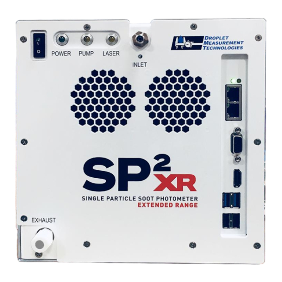
Strict observance of the following Warning labels is advised. Back panel of the SP2-XR Exterior of the laser frame: Interlock switches: Back panel of the SP2-XR DOC-0425 Rev A © 2018 DROPLET MEASUREMENT TECHNOLOGIES LLC... -
Page 9: Interface Features
DMT UHSAS integrated optical block. The SP2-XR uses one scattering and one incandescence detector. The particle peak processing is done in the instrument firmware and software which provides data without the need for two pass processing. DOC-0425 Rev A © 2018 DROPLET MEASUREMENT TECHNOLOGIES LLC... -
Page 10: Unpacking And Setup
The optional ground is generally used to protect the instrument in an airplane. 3. If there is a plug on the inlet tube, be sure to remove it before powering up the instrument. DOC-0425 Rev A © 2018 DROPLET MEASUREMENT TECHNOLOGIES LLC... -
Page 11: Steps For Powering-Up The System
NOTE: If the Laser is on and the pump has been turned off, the pump will be prevented from being re-activated until the laser is turned off. Turn off the laser, then the pump can be activated. DOC-0425 Rev A © 2018 DROPLET MEASUREMENT TECHNOLOGIES LLC... -
Page 12: Powering The System Down
3.) Shut down the SP2-XR software by selecting File > Exit. 4.) Turn off the SP2-XR instrument using the System Power switch located on the left front corner of the unit. DOC-0425 Rev A © 2018 DROPLET MEASUREMENT TECHNOLOGIES LLC... -
Page 13: Sp2-Xr Software
The data is automatically zipped when the preset number of particles are captured. • Threshold data files – Relates the A/D particle signal counts to the particle size. These tables are developed by the SP2-XR calibration program. DOC-0425 Rev A © 2018 DROPLET MEASUREMENT TECHNOLOGIES LLC... -
Page 14: Sp2-Xr Quick-Start
• Check the status area in the upper right (Figure 3) to make sure the Pump and laser are on and running. • Figure 3: Choose the correct Config file DOC-0425 Rev A © 2018 DROPLET MEASUREMENT TECHNOLOGIES LLC... -
Page 15: Figure 4: Choosing Parameters
“Auto Scale X/Y” option. Once the auto scale is turned off, the user can adjust minimum and maximum values of the graph by clicking on the axis and entering the desired value. DOC-0425 Rev A © 2018 DROPLET MEASUREMENT TECHNOLOGIES LLC... -
Page 16: Figure 5: File Tab
The data file name and location will be shown in the Data File Path box (Figure 7) on the upper left of the single particle SP2-XR screen. Figure 5: File tab Figure 6: Data File tab DOC-0425 Rev A © 2018 DROPLET MEASUREMENT TECHNOLOGIES LLC... -
Page 17: Sp2-Xr Main Screen
The Pause Display toggle (D) will pause the data visualization display for closer inspection of a particular data event, or to save a screen capture of the event. Figure 7: Verifying particle response DOC-0425 Rev A © 2018 DROPLET MEASUREMENT TECHNOLOGIES LLC... -
Page 18: Sequence Tab
The Sequence Tab (Figure 8) is a quick reference to all of the Sequences available. It shows which ones are running, and which state they are in. Specific sequences can be turned on and off by pressing the “Running” button. DOC-0425 Rev A © 2018 DROPLET MEASUREMENT TECHNOLOGIES LLC... -
Page 19: Histograms Tab
The particles per sample period are recorded in the top right field (A). The Pause Display toggle will pause the data visualization display for closer inspection of a particular data event, or to save a screen capture of the event. DOC-0425 Rev A © 2018 DROPLET MEASUREMENT TECHNOLOGIES LLC... -
Page 20: Single Particle Tab
.ini file when the SP2-XR program is closed. See Appendix A for a schematic of particle traces and how these parameters are applied. DOC-0425 Rev A © 2018 DROPLET MEASUREMENT TECHNOLOGIES LLC... -
Page 21: Custom Tab
(Figure 11) shows The Custom tab (Figure 13) has two Custom data displays (B). Each of the charts provided, are user configurable and can display up to 8 channels on two y axis’. Figure 11: Custom tab DOC-0425 Rev A © 2018 DROPLET MEASUREMENT TECHNOLOGIES LLC... -
Page 22: Config Tab
Reset to defaults: This button will reset the .ini file to the factory default values. Should the .ini file become corrupted, this method should get the user back to an operational state. DOC-0425 Rev A © 2018 DROPLET MEASUREMENT TECHNOLOGIES LLC... -
Page 23: Config / Acquisition Tab
The parameters: Laser Temp Set, Laser Current Set, Crystal Temp Set (not active), APD HV set, and PMT HV Set, are operationally critical defaults and should not be changed without consulting Droplet Management Technologies prior to making those changes. •... -
Page 24: Config / Settings Tab
Hysteresis allows the alarm to be configured such that small amounts of noise near the threshold value will not continually set and clear the alarm. For the < and <= commands, once DOC-0425 Rev A © 2018 DROPLET MEASUREMENT TECHNOLOGIES LLC... -
Page 25: Figure 15: Config / Alarms
Set this to 0 to have an alarm work as soon as the condition is detected. If Min Time is set to a larger value, short excursions past the alarm condition will not cause the action to be executed. DOC-0425 Rev A © 2018 DROPLET MEASUREMENT TECHNOLOGIES LLC... -
Page 26: Config / Sequences
It is also used programmatically to refer to the alarm so that its threshold can be changed by a sequence, CCL command, or another alarm. Figure 16: Config / Sequences tab DOC-0425 Rev A © 2018 DROPLET MEASUREMENT TECHNOLOGIES LLC... -
Page 27: Config / Custom
Graph 1 Plots and Graph 2 plots allows the selection of up to seven channels to display. The Y axis (left or right) for each plot can be individually selected. Figure 17: Config / Custom tab DOC-0425 Rev A © 2018 DROPLET MEASUREMENT TECHNOLOGIES LLC... -
Page 28: Alarms Window
Min Time: 0 Set Value: 0 Sequence: near. Target Channel: near. This alarm causes the program to begin writing data to a file after the program has run for 60 seconds. DOC-0425 Rev A © 2018 DROPLET MEASUREMENT TECHNOLOGIES LLC... - Page 29 This alerts the user to the error condition even when the program is not displaying the status tab. Example 4: Name: Reduce Laser Cur Channel: YAG Crystal Temp Condition: > Threshold: 35 Hysteresis: 0 Action: Set Channel Min Time: 60 Set Value: 2000 Sequence: near. DOC-0425 Rev A © 2018 DROPLET MEASUREMENT TECHNOLOGIES LLC...
-
Page 30: System Settings Tab
Flow Control, laser and fan settings • File writing options, locations and data file notes input. • Sequence viewing and toggle on/off • Start-up Config, Threshold tables, and F files • Administrator login DOC-0425 Rev A © 2018 DROPLET MEASUREMENT TECHNOLOGIES LLC... -
Page 31: Utility Window
The Utility window (Figure 20) has functions and windows for viewing data and logs. 5.11.1 Utility – Data Reader Figure 20: Utility – Data Reader 5.11.2 Utility – Log reader Figure 21: Utility Log Reader DOC-0425 Rev A © 2018 DROPLET MEASUREMENT TECHNOLOGIES LLC... -
Page 32: Status Window
Calibration alarms are logged in the lower right (A). When status is red and alarm notes show that unit has exceeded its calibration limits, please call DMT for further instruction. DOC-0425 Rev A © 2018 DROPLET MEASUREMENT TECHNOLOGIES LLC... -
Page 33: Laser Safety Interlocks
The laser can also be turned off from the software interface by clicking on the Actions Tab on the main screen navigation bar, or F8 as a keyboard shortcut. DOC-0425 Rev A © 2018 DROPLET MEASUREMENT TECHNOLOGIES LLC... -
Page 34: Routine Maintenance
NOTE: Avoid hitting the side of the cleaning port with the Q-tip, as grease from the O-ring can get on the Q-tip and smear the optics. DOC-0425 Rev A © 2018 DROPLET MEASUREMENT TECHNOLOGIES LLC... -
Page 35: Figure 26: Cleaning The Optics
Check that the laser has not shut off. Check that the Laser off or no sample started, but no particles are sample flow is positive. Check the laser interlocks are flow. seen on the display. engaged (i.e., depressed). DOC-0425 Rev A © 2018 DROPLET MEASUREMENT TECHNOLOGIES LLC... -
Page 36: Appendix A: Theory Of Operation
SP2-XR, which detects single particle scattering at 1064 nm. The scattering detector can be used to detect non-BC-containing aerosol number and optical particle size. Processing Electronics Figure 27: SP2-XR Processing electronics DOC-0425 Rev A © 2018 DROPLET MEASUREMENT TECHNOLOGIES LLC... - Page 37 XR application, the goal is to contain the power within the cavity between the mirrors (open-cavity laser) and utilize it directly. The power in the cavity is approximately 1 Mw per cm . The YAG laser DOC-0425 Rev A © 2018 DROPLET MEASUREMENT TECHNOLOGIES LLC...
- Page 38 The incandescence channel uses a photomultiplier tube (PMT) that measures the incandescence signal in the visible region. This channel is optically filtered to pass broadband light, nominally from 400-750nm. DOC-0425 Rev A © 2018 DROPLET MEASUREMENT TECHNOLOGIES LLC...
-
Page 39: Appendix B: Particle Size / Shape Determination
This is based on threshold crossings and is the maximum absolute value of incandescence delay. NOTE: All time values are in clock counts of 25ns. DOC-0425 Rev A © 2018 DROPLET MEASUREMENT TECHNOLOGIES LLC... -
Page 40: Appendix C: Particle By Particle Data Files
Time when incandescent particle crosses the Incand Peak Time leading threshold until peak maximum, clock counts HWHM for the width of the incandescent peak, Incand FWHM clock counts DOC-0425 Rev A © 2018 DROPLET MEASUREMENT TECHNOLOGIES LLC... -
Page 41: Appendix D: Housekeeping Data Files
Laser TEC Sense Driving current to the Laser TEC Laser Over Temp (On/Off) True or High if laser over temp is observed +5V Laser Rail (V) Absolute pressure in the cell DOC-0425 Rev A © 2018 DROPLET MEASUREMENT TECHNOLOGIES LLC... - Page 42 FAN3 RPM Spare Tach Reserved /unused Dual Qualified Scatter and incandescence Number of particles qualified for both scatter and Particles incandescence Qualified Scatter Only Particles Number of particles qualified for scattering DOC-0425 Rev A © 2018 DROPLET MEASUREMENT TECHNOLOGIES LLC...
- Page 43 Flag for channel being under threshold ABD-0408 HKADCs max Flag for channel being over threshold ABD-0436 HKADCs max Flag for channel being over threshold Concentration of particles showing an incandescent incandescence Particle Conc (cts/cc) signal DOC-0425 Rev A © 2018 DROPLET MEASUREMENT TECHNOLOGIES LLC...
- Page 44 Set point for high voltage on incandescence PMT HV SP photomultiplier PbP Packet Time Timestamped PbP packet Scatter Bin 1-27 Number of particles in scattering bin 1-27 Incand-Bin 1-27 Number of particles in Incandescence bin 1-27 DOC-0425 Rev A © 2018 DROPLET MEASUREMENT TECHNOLOGIES LLC...
Need help?
Do you have a question about the SP2XR and is the answer not in the manual?
Questions and answers