
Related Manuals for Droplet SP2-XR


Summary of Contents for Droplet SP2-XR
- Page 1 SP2-XR Single Particle Soot Photometer - Extended Range Operator Manual 2400 Trade Centre Avenue Longmont, CO 80503 USA DOC-0425 Revision D A L L R I G H T S R E S E R V E D...
-
Page 2: Table Of Contents
SP2-XR Software ......................21 1.12 Output Data file types ......................21 1.13 SP2-XR Quick-Start ......................22 1.14 SP2-XR Main Screen ......................26 1.15 Histograms Tab ........................27 1.16 Config Tab ..........................28 Config / Acquisition Tab ....................... 30 Config / Settings Tab ........................31 Config / Alarms Tab ........................ - Page 3 Appendix C: Particle Size / Shape determination ............57 Appendix D: Particle by Particle data files ..............58 Appendix E: Housekeeping data files ................60 Appendix F: Single Particle Trace Files ................62 Appendix G: Mounting Information ................63 DOC-0425 Rev D © 2019 DROPLET MEASUREMENT TECHNOLOGIES LLC...
- Page 4 F i g u r e s Figure 1: SP2-XR Labels ....................9 Figure 2: Front and Rear view of the SP2-XR..............10 Figure 3: SP2-XR Aerosol Flow..................13 Figure 4: SP2-XR Power Connections and Cables ............19 Figure 5: SP2-XR Power Switch ..................19 Figure 6: SP2-XR Screen with Actions Tab ...............
- Page 5 Figure 37: SP2-XR Key in the locked (laser off) position ..........49 Figure 38: Cleaning port access to optics ............... 50 Figure 39: Cleaning the Optics ..................51 Figure 41: SP2-XR Aerosol Flow ..................54 Figure 42: SP2-XR Optical Diagram ................55 Figure 43: SP2-XR Particle trace schematic ..............
-
Page 6: Specifications
5 to 95% non-condensing 400GB – 15 days of continuous data storage with nominal sample Data Storage Capacity concentration of 1,000 particles / cm and a standard flow rate of 100 volumetric cm /minute. DOC-0425 Rev D © 2019 DROPLET MEASUREMENT TECHNOLOGIES LLC... -
Page 7: Electrical Specifications
1.4 Physical Specifications Weight: 13 Kg (28.5lbs) for SP2-XR Instrument 21 cm W x 21 cm H x 42 cm L (Actual) Not including inlet hardware Dimensions: and fuses. 61 cm W x 35.5 cm H x 63.5 cm L (Actual) Shipping Container: 32.3 Kg (69 lbs.) -
Page 8: General Information
General Information In no event will Droplet Measurement Technologies, LLC (DMT) be liable for direct, indirect, special, incidental or consequential damages resulting from any defect or omissions in this manual. DMT reserves the right to make changes to this manual and the products it describes at any time, without notice or obligation. -
Page 9: Safety Information
Laser Safety The SP2-XR is a Class 1 Laser Product when fully enclosed. Removing the outer enclosure, or the power monitor will expose a Class IIIB laser, 1064 nm, with power of approximately 200 mW. Disassembly of the pump laser can expose a Class 4, 808 nm with power up to 3W. -
Page 10: Interface Features
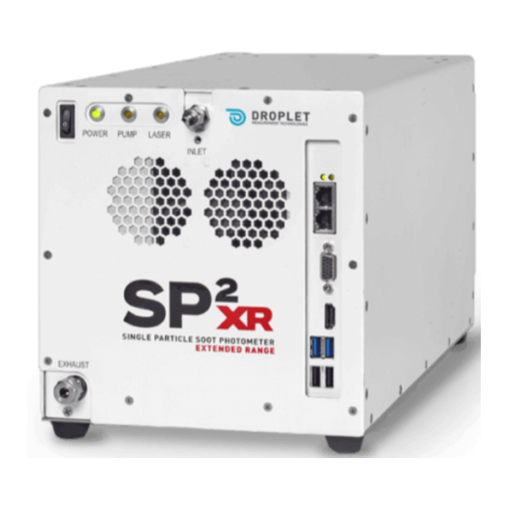
1.6 Interface Features The SP2-XR input and output features are shown in Figure 2 below Figure 2: Front and Rear view of the SP2-XR Power switch HDMI Port Function indicators Monitor Port (VGA) Inlet flow (remove plug prior to power-up) -
Page 11: Brief Theory Of Operation
The SP2-XR uses a sample flow controller to control the flow rate of aerosol sample pulled into SP2- XR. The sample is drawn through the sample inlet and then injected into the optical cavity and surrounded by the recirculating sheath flow air system to ensure that the particles are directed through the laser beam. - Page 12 Flow control Analog monitor and monitor Analog monitor particle peak detector Digital electronics (4) Monitor Histogramming control functions PC and Display (5) Figure 3: Block Diagram of the SP2-XR DOC-0425 Rev D © 2019 DROPLET MEASUREMENT TECHNOLOGIES LLC...
-
Page 13: Figure 3: Sp2-Xr Aerosol Flow
Once the sample passes through the optical cavity it will flow through several filters and then either be used as make-up air for the sheath flow, or it will be ejected through the outlet of the SP2-XR depending on the setting for the sheath flow. -
Page 14: Introduction
In addition to a smaller footprint, the software and firmware included with the SP2-XR provides final data output in real time without the need for two pass processing. - Page 15 This detector serves as a reference for changes in laser power. The Mechanical Housing The laser and detection optics are built into the optical block, which is a sealed mechanical enclosure. See the following figures. DOC-0425 Rev D © 2019 DROPLET MEASUREMENT TECHNOLOGIES LLC...
- Page 16 Figure 5 laser. The detector is located at 90 to the path of the particle through the laser. (The laser can be DOC-0425 Rev D © 2019 DROPLET MEASUREMENT TECHNOLOGIES LLC...
- Page 17 For the purpose of calculating scattering cross sections with Mie scattering, the collection angles are 33 -75.2 and 104.8 -147 The Figure below shows a top view of the optical block: DOC-0425 Rev D © 2019 DROPLET MEASUREMENT TECHNOLOGIES LLC...
-
Page 18: Unpacking, Setup, Installation, And Power Up
If using in a laboratory setting, simply follow section 1.10 Setup to proceed. If using in a mobile setting and/or on an aircraft, care must be taken in mounting the SP2-XR. See Appendix G: Mounting Information to ensure that you take care to mount the SP2-XR properly. -
Page 19: Figure 4: Sp2-Xr Power Connections And Cables
Connect the plug to a properly grounded receptacle. Be sure to use power-surge protection for your instrument. 4. Power-up the SP2-XR using the System Power switch located on the front panel. Figure 5: SP2-XR Power Switch 5. Start the SP2-XR software by double-clicking the SP2-XR icon on desktop. -
Page 20: Powering The System Down
Failure to do so may result in damage to the instrument. Figure 6: SP2-XR Screen with Actions Tab 1.11 Powering the System Down 1. On the SP2-XR software’s Actions tab (Figure 6) toggle Laser Off. WARNING: Laser Power must be turned off before the pump is turned off. -
Page 21: Sp2-Xr Software
Any changes made here will not be saved in the .ini file. These programs are loaded on the C: drive of the SP2-XR and a backup copy is provided on the memory stick shipped with the unit. -
Page 22: Sp2-Xr Quick-Start
1.13 SP2-XR Quick-Start When the SP2-XR.exe program is first opened, the main SP2-XR screen will appear with a histogram plot detailing measured particles on the left and time-series plots for recorded parameters on the right (Figure 7). Each of the tabs along the top will bring up a new screen allowing for instrument control or display of parameters. -
Page 23: Figure 8: Check The Config File And Status
• Check the status bar in the upper right to make sure the pump and laser are on and running. • Go back to the Main SP2-XR tab (Figure 9) and set parameter to “Sample Flow Controller Read, VCCM”. •... -
Page 24: Figure 9: Choosing Parameters
Figure 9: Choosing parameters By default, the x and y axis of the plots will auto scale as data is collected. DOC-0425 Rev D © 2019 DROPLET MEASUREMENT TECHNOLOGIES LLC... -
Page 25: Figure 10: File Tab
The Recording/Not Recording button in the status bar shows whether or not data is being written to a file. The data file path will be shown in the Data Folder box on the upper left of the SP2-XR tab. Figure 11: Data File tab DOC-0425 Rev D ©... -
Page 26: Sp2-Xr Main Screen
1.14 SP2-XR Main Screen The following section details the SP2-XR main screen (Figure 12). • shows the data file path, as well as the number of particles saved to the file. • shows the housekeeping time series plots. The time series displayed is configurable at points (1). -
Page 27: Histograms Tab
“Auto Scale X/Y” option. Once the auto scale is turned off, the user can adjust minimum and maximum values of the graph by clicking on the labels and entering the desired value. DOC-0425 Rev D © 2019 DROPLET MEASUREMENT TECHNOLOGIES LLC... -
Page 28: Config Tab
• Data file Path: The SP2-XR software is stored on the C: drive. Any files saved to the C: drive will be deleted upon instrument shut down. Data should be stored on the D: drive or an external drive. - Page 29 • The Parameters: Laser Temp Set and Laser Current Set are operationally critical defaults and should not be changed without consulting Droplet Management Technologies prior to making those changes. • Graph Backgrounds: Allows the user to change the default background color of the time-series plots.
-
Page 30: Config / Acquisition Tab
Figure 15: Config / Acquisition tab The Acquisition tab is shown in Figure 15. This tab contains equations for scaling A/D counts to housekeeping parameters. These values should not be changed unless directed by DMT. DOC-0425 Rev D © 2019 DROPLET MEASUREMENT TECHNOLOGIES LLC... -
Page 31: Config / Settings Tab
These are generated at DMT and are instrument specific. Config / Alarms Tab Alarms allow the user to monitor any of the SP2-XR housekeeping parameters and set an action or series of actions if certain criteria are met. •... -
Page 32: Figure 17: Config / Alarms Tab
Note: when an alarm condition is met but the minimum time has not yet elapsed, the alarm goes into a warning state, indicated by a Yellow alarm color. Figure 17: Config / Alarms tab DOC-0425 Rev D © 2019 DROPLET MEASUREMENT TECHNOLOGIES LLC... -
Page 33: Config / Sequences Tab
• Include Exit Step: allows one to save the currently-highlighted Sequence in a small .seq file. • Exit Step Box: Allows the user to configure the settings of the exit step. DOC-0425 Rev D © 2019 DROPLET MEASUREMENT TECHNOLOGIES LLC... -
Page 34: Config / Custom Tab
Graph 1 Plots and Graph 2 plots allows the selection of up to seven channels to display. The Y- axis (left or right) for each plot can be individually selected. Figure 19: Config / Custom tab DOC-0425 Rev D © 2019 DROPLET MEASUREMENT TECHNOLOGIES LLC... -
Page 35: Alarms Tab
Min Time: 0 Set Value: 0 Sequence: near. Target Channel: near. This alarm causes the program to begin writing data to a file after the program has run for 60 seconds. DOC-0425 Rev D © 2019 DROPLET MEASUREMENT TECHNOLOGIES LLC... - Page 36 This alerts the user to the error condition even when the program is not displaying the status tab. Example 4: Name: Reduce Laser Cur Channel: YAG Crystal Temp Condition: > Threshold: 35 Hysteresis: 0 Action: Set Channel Min Time: 60 Set Value: 2000 Sequence: near. Target Channel: MonPumpLaser DOC-0425 Rev D © 2019 DROPLET MEASUREMENT TECHNOLOGIES LLC...
- Page 37 Timer channels can be defined. The only parameter for a Timer channel is its name. Each Timer starts with a value of 0 when the SP2-XR program starts and counts up in units of seconds. A Timer can be set to any value using the Set Channel button on the Control tab, or using a sequence, Alarm, or CCL action.
-
Page 38: System Settings Tab
File writing options, locations and data file notes input: Allows the user to select the type of file, maximum size, and file location. • Sequence viewing and toggle on/off: Allows the user to see all sequences on the SP2-XR and turn each on or off. •... -
Page 39: Utility Window
Utilities dropdown menu. Utility – Data Reader Figure 22: Utility – Data Reader The data reader allows the user to load and read a file from a previously written experiment. DOC-0425 Rev D © 2019 DROPLET MEASUREMENT TECHNOLOGIES LLC... -
Page 40: Utility - Log Reader
Utility – Log reader Figure 23: Utility Log Reader The Log Reader allows the user to load a log file to find out more about the status of the SP2XR throughout the experiment. DOC-0425 Rev D © 2019 DROPLET MEASUREMENT TECHNOLOGIES LLC... -
Page 41: Status Window
If a calibration alarm shows a parameter is outside of calibrated limits during operation, the instrument must be sent to DMT for service. DOC-0425 Rev D © 2019 DROPLET MEASUREMENT TECHNOLOGIES LLC... -
Page 42: Laser Beam Profiler Software
Laser Beam Profiler Software The SP2-XR contains an internal camera that is permanently mounted and that can be used to view the laser beam profile. The profile can be used as a reference to the laser beam heath and alignment to determine if maintenance or service may be required. -
Page 43: Figure 26: Front Panel Connections
Figure 26: Front panel connections 2. Tilt the front panel away from the instrument. Locate and disconnect the connections for the front panel fan and temperature sensor (Figure 26). Figure 27: Laser power monitor board DOC-0425 Rev D © 2019 DROPLET MEASUREMENT TECHNOLOGIES LLC... -
Page 44: Figure 28: Laser Power Board Removal
5. Now the laser power monitor can be removed from laser cavity. It is recommended that the power monitor board be kept in an electronics ESD bag to prevent short circuiting since it will DOC-0425 Rev D © 2019 DROPLET MEASUREMENT TECHNOLOGIES LLC... -
Page 45: Figure 30: Front Panel Connections 2
(Figure 29). Figure 30: Front panel connections 2 6. Connect the front panel fan and temperature sensor connections and install the front cover (Figure 30). DOC-0425 Rev D © 2019 DROPLET MEASUREMENT TECHNOLOGIES LLC... -
Page 46: Running The Software
Figure 31: vBeam application 1. When the instrument is running, navigate to the desktop screen. Double-click on the icon labeled “vBeam” (Figure 31). Figure 32: Video board selection DOC-0425 Rev D © 2019 DROPLET MEASUREMENT TECHNOLOGIES LLC... -
Page 47: Figure 33: Resolution And Bit Depth Selection
3. After clicking the part number, the software will generate options under the bottom box labeled “Select a resolution and bit depth”. Click on the desired resolution (Figure 33). Figure 34: vBeam play button DOC-0425 Rev D © 2019 DROPLET MEASUREMENT TECHNOLOGIES LLC... -
Page 48: Figure 35: Vbeam Exposure Time
5. The default exposure time is 90.00ms. This will need adjusted, change to 50.00ms first. Then adjust as necessary for the desired representation of the beam. (The laser must be enabled from the SP2-XR software for viewing, see section 4.2.) DOC-0425 Rev D... -
Page 49: Laser Safety Interlocks
Laser Safety Interlocks The SP2-XR features two types of laser safety interlocks that operate in series. The first (Figure 36) is a cabinet laser safety interlock that disables the laser if the cover or face plate of the unit is removed. Be careful to make sure the interlock is not intentionally or accidentally pressed down if the cover has been removed from the unit. -
Page 50: Routine Maintenance
1.23 Cleaning the Laser Optics The optics used in the SP2-XR have reflectivity of 99.97% or better, and it is very difficult to clean them without causing damage or contamination. DMT recommends consultation with our support teams to determine if the user should attempt to clean the optics on site. -
Page 51: Figure 39: Cleaning The Optics
This is the crystal/laser end. Make sure the Laser is OFF, and be gentle, as the crystal end is delicate and scratches easily. NOTE: Only clean the crystal end when all other cleaning efforts have been exhausted. DOC-0425 Rev D © 2019 DROPLET MEASUREMENT TECHNOLOGIES LLC... -
Page 52: Troubleshooting
Should you have any additional questions or comments, please contact us via telephone at +1 (303) 440-5576, or email at customer-contact@dropletmeasurement.com. To learn more about what is new at Droplet Measurement Technologies, please visit our website at http://www.dropletmeasurement.com. DOC-0425 Rev D... -
Page 53: Appendix A: Expanded Theory Of Operation
This mass measurement is independent of the particle mixing state, and hence the SP2-XR is a reliable measure of the black carbon mass concentration. Since the SP2-XR detects single particles, the SP2-XR also measures the black carbon mass concentration. -
Page 54: Figure 41: Sp2-Xr Aerosol Flow
Laser Characteristics The heart of the SP2-XR is the Nd:YAG laser. This will be referred to in the following discussion simply as the YAG laser. Figure 43 shows a diagram of the laser and the main optical components. The laser cavity consists of a gain medium, the YAG crystal, and the output coupler. -
Page 55: Figure 42: Sp2-Xr Optical Diagram
The laser beam is Gaussian in shape, nominally 230 microns width at 90% power level. The YAG laser is central to the system. The two detectors are oriented in the plane of the SP2-XR optical diagram as shown in (Figure 42). The aerosol jet is perpendicular to the plane of the SP2-XR optical diagram and sends the particles across the laser beam. -
Page 56: Appendix B: Warranty And Contact Information
Consumable components such as tubing, filters, pump diaphragms, and Nafion dehumidifiers and dehumidifiers are not covered by this warranty. Service procedures and repairs are warrantied for 90 days. Droplet Measurement Technologies, LLC can be contacted at the following address: Droplet Measurement Technologies, LLC 2400 Trade Centre Avenue... -
Page 57: Appendix C: Particle Size / Shape Determination
Appendix C: Particle Size / Shape determination Particle Trace Schematic Figure 43: SP2-XR Particle trace schematic Particle Parameter Settings: • Transit Time Min: Minimum transit time for a particle, this is set to reject very short electronic or optical noise spikes. -
Page 58: Appendix D: Particle By Particle Data Files
Time between when the scattering peak and the Incand Delay incandescence peak cross the threshold for each particle microseconds Incandescence particle mass in femtograms based Incand Mass (fg) on the incandescence threshold table DOC-0425 Rev D © 2019 DROPLET MEASUREMENT TECHNOLOGIES LLC... - Page 59 Number of seconds since January, 1, 1904 midnight LV Time Stamp (UTC sec) UTC/GMT. *These flags are binary values, a value of 1 indicates the condition was present, and value of 0 indicates the condition was not present. DOC-0425 Rev D © 2019 DROPLET MEASUREMENT TECHNOLOGIES LLC...
-
Page 60: Appendix E: Housekeeping Data Files
Pressure reading in the sheath flow controller Sheath Flow Controller Temperature (C) Temperature reading on the sheath flow controller Sample Flow Controller Read (vccm) (Volume) Flow reading from the sample flow controller DOC-0425 Rev D © 2019 DROPLET MEASUREMENT TECHNOLOGIES LLC... - Page 61 Bandwidth Incandescence Low Incandescence low gain channel baseline noise Bandwidth Incandescence High Incandescence high gain channel baseline noise Number of seconds since January, 1, 1904 midnight LV Time Stamp (UTC sec) UTC/GMT. DOC-0425 Rev D © 2019 DROPLET MEASUREMENT TECHNOLOGIES LLC...
-
Page 62: Appendix F: Single Particle Trace Files
Single Precision Real Reserved Reserved Single Precision Real Reserved Reserved Single Precision Real Reserved Reserved Double Precision Real Reserved Reserved Double Precision Real Reserved Reserved 1D array of Single Precision Real Reserved DOC-0425 Rev D © 2019 DROPLET MEASUREMENT TECHNOLOGIES LLC... -
Page 63: Appendix G: Mounting Information
Appendix G: Mounting Information Requirements for Custom Mounting Solutions The SP2-XR may be mounted in on an aircraft rack as long as the laser cooling fan on the underneath side of the instrument has sufficient clearance to draw air for proper laser operation.
Need help?
Do you have a question about the SP2-XR and is the answer not in the manual?
Questions and answers