Table of Contents
Advertisement
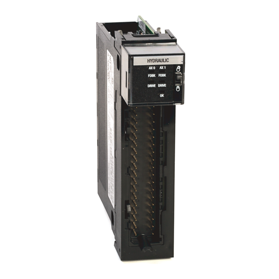
SSI Servo Module
(Catalog Number 1756-M02AS)
The Synchronous Serial Interface (SSI) Servo Module mounts in a
ControlLogix™ chassis and uses a removable terminal block (RTB) to
connect all field-side wiring.
Before you install your module you should have:
• installed and grounded a 1756 chassis and power supply.
• ordered and received an RTB and its components for your
application.
To:
Installation Instructions
Publication
1756-IN595A-EN-P - March 2004
See page:
4
5
6
7
8
10
11
12
12
13
13
14
19
20
21
Back Cover
Advertisement
Table of Contents

Related Manuals for Allen-Bradley 1756-M02AS


Summary of Contents for Allen-Bradley 1756-M02AS
-
Page 1: Table Of Contents
Installation Instructions SSI Servo Module (Catalog Number 1756-M02AS) The Synchronous Serial Interface (SSI) Servo Module mounts in a ControlLogix™ chassis and uses a removable terminal block (RTB) to connect all field-side wiring. Before you install your module you should have: •... - Page 2 2 SSI Servo Module Important User Information Solid state equipment has operational characteristics differing from those of electromechanical equipment. Safety Guidelines for the Application, Installation and Maintenance of Solid State Controls (Publication SGI-1.1 available from your local Rockwell Automation sales office or online at http://www.ab.com/manuals/gi) describes some important differences between solid state equipment and hard-wired electromechanical devices.
- Page 3 Also, see the appropriate sections in this publication, as well as the Allen-Bradley publication 1770-4.1 (“Industrial Automation Wiring and Grounding Guidelines”), for additional installation requirements pertaining to this equipment.
-
Page 4: Note The Power Requirements
4 SSI Servo Module Removal and Insertion Under Power When you insert or remove the module while backplane power WARNING is on, an electrical arc can occur. This could cause an explosion in hazardous location installations. Be sure that power is removed or the area is nonhazardous before proceeding. -
Page 5: Identifying Module Components
SSI Servo Module 5 Identifying Module Components You received two components with your order: • 1756-M02AS module • RTB door label If you did not receive these components, contact your Rockwell Automation representative. This module mounts in a 1756 chassis and uses a separately-ordered RTB or a Bulletin 1492 Interface Module (IFM) to connect all field-side wiring. -
Page 6: Installing The Module
6 SSI Servo Module Installing the Module You can install or remove the module while chassis power is applied. When you insert or remove the module while backplane power is WARNING on, an electrical arc can occur. This could cause an explosion in hazardous location installations. -
Page 7: Keying The Module & Removable Terminal Block/Interface Module
SSI Servo Module 7 2. Slide the module into the chassis until module tabs ‘click’. Locking Tab 20862-M Figure 2 Module Locking Tabs Keying the Module and Removable Terminal Block/Interface Module Use the wedge-shaped keying tabs and U-shaped keying bands to prevent connecting the wrong wires to your module. -
Page 8: Wiring A Removable Terminal Block (Rtb)
4. Push the tab until it stops. Reposition the tabs to rekey future module applications. Wiring a Removable Terminal Block (RTB) Your 1756-M02AS module uses two types of RTBs (each RTB comes with housing) to connect wiring. • Cage clamp - Catalog number 1756-TBCH •... - Page 9 SSI Servo Module 9 Connect the wires as shown below. Spring Clamp RTB Cage Clamp RTB 1. Strip 7/16 inch (11mm) maximum 1. Strip 3/8 inch (9.5mm) maximum length of wire. length of wire. 2. Insert the screwdriver into the 2.
-
Page 10: Wiring To A Servo Module
10 SSI Servo Module Wiring to a Servo Module Use the wiring example in the following figure to wire to your module. +OUT-0 +OUT-1 General cable To Servo Drive C0720 -OUT-0 -OUT-1 or valve +ENABLE-0 +ENABLE-1 -ENABLE-0 -ENABLE-1 General cable To Servo Drive, C0721 DRVFLT-0... -
Page 11: Wiring Registration Sensors
24V dc servo module inputs. 24 V dc Power Supply 24 Volt – Registration Sensor Supply From Output REG24V General cable 1756-M02AS C0720 Common IN_COM 43395 Figure 7 - 24V Registration Sensor 5 V dc Power Supply 5 Volt – Registration Sensor... -
Page 12: Wiring The Home Limit Switch
E- stop string, which controls power to the associated pumps. The OK contacts are rated to drive an external 24V dc pilot relay (for example, Allen-Bradley 700- HA32Z24) whose contacts can be incorporated into the E- Stop string as in the following figure. -
Page 13: Assembling The Removable Terminal Block And The Housing
SSI Servo Module 13 Assembling the Removable Terminal Block and the Housing 1. Align the grooves at the bottom of the housing with the side edges of the RTB. Groove Side edge of the RTB Groove Strain relief area Side edge of the RTB 2. -
Page 14: Checking The Led Indicators
14 SSI Servo Module 1. Align the module and RTB guides to 2. Press quickly and evenly to seat the RTB make sure the module will seat properly. until the latches snap into place. Locking tab Module guide 20853–M 20854–M RTB guides 3. - Page 15 • If you have configured the data over the backplane. module, check the slot number in the 1756-M02AS Properties dialog box. Steady green One of the following: None • Module is...
- Page 16 16 SSI Servo Module If the OK LED The module status is: Take this action: displays: Steady red light One of the following: • A potential non- • Reboot the module. recoverable fault • If the solid red persists, replace has occurred.
- Page 17 SSI Servo Module 17 If the FDBK The module status is: Take this action: LED displays: • Correct the source of the Flashing red The axis servo loop error light tolerance has been problem. exceeded. • Clear the servo fault condition using the Motion Axis Fault Reset instruction.
- Page 18 18 SSI Servo Module The table below provides an explanation of the DRIVE indicator. If the DRIVE The module status is: Take this action: LED displays: One of the following: • The axis is not • None, if the axis is not used or used.
-
Page 19: Removing The Removable Terminal Block From The Module
SSI Servo Module 19 If the DRIVE The module status is: Take this action: LED displays: • Check for faults that may have Flashing red The axis drive output is in light the shutdown state. generated this state. • Execute the Motion Axis Shutdown Reset instruction. -
Page 20: Removing The Module
20 SSI Servo Module You must remove the RTB before removing the module. 1. Unlock the locking tab at 2. Open the RTB door and pull the top of the module. the RTB off the module. 42517 20855–M Figure 16 Removing the RTB Removing the Module 1. -
Page 21: 1756-M02As Specifications
SSI Servo Module 21 1756-M02AS Specifications Number of axes 2 axes maximum Servo loop Type External Drive = Torque Position Loop: PID with Velocity Feedforward Velocity Loop: PI with Accel Feedforwrd (nested); with Directional Scaling and Friction Compensation External Drive = Velocity... -
Page 22: Publication 1756-In595A-En-P - March
22 SSI Servo Module Registration inputs Type Optically isolated, current sinking input 24V dc input voltage +24V dc nominal Maximum 26. 4V dc Minimum on 18. 5V dc Maximum off 3.5V dc 5V dc input voltage +5V dc nominal Maximum 5.5V dc Minimum on 3.7V dc... - Page 23 SSI Servo Module 23 Isolation Voltage User to System 30V continuous RTB keying User-defined Field wiring arm 36-position RTB (1756-TBCH or -TBS6H) RTB screw torque (cage clamp) 4.4 inch-pounds (0.4Nm) maximum Conductors Wire size #22 to #14 AWG (0.324 to 2.08 sq. mm) stranded 3/ 64 inch (1.2 mm) insulation maximum Category Screwdriver blade width for RTB...
- Page 24 24 SSI Servo Module ESD Immunity IEC 61000-4-2: 6kV contact discharges 8kV air discharges Radiated RF Immunity IEC 61000-4-3: 10V/m with 1kHz sine-wave 80%AM from 80MHz to 2000MHz 10V/m with 200Hz 50% Pulse 100%AM at 900Mhz EFT/B Immunity IEC 61000-4-4: ±2kV at 5kHz on signal ports Surge Transient Immunity IEC 61000-4-5:...
- Page 25 SSI Servo Module 25 The following information applies when Informations sur l’utilisation de cet équipement operating this equipment in hazardous en environnements dangereux: locations: Products marked “CL I, DIV 2, GP A, B, C, D” are Les produits marqués “CL I, DIV 2, GP A, B, C, D” ne suitable for use in Class I Division 2 Groups A, B, conviennent qu’à...
-
Page 26: Rockwell Automation Support
Rockwell Automation Support Rockwell Automation provides technical information on the web to assist you in using our products. At http://support.rockwellautomation.com, you can find technical manuals, a knowledge base of FAQs, technical and application notes, sample code and links to software service packs, and a MySupport feature that you can customize to make the best use of these tools.
Need help?
Do you have a question about the 1756-M02AS and is the answer not in the manual?
Questions and answers