
Related Manuals for SENSTAR OmniTrax


Summary of Contents for SENSTAR OmniTrax
- Page 1 ® OmniTrax Ranging Buried Cable Intrusion Detection Sensor Product Guide A4DA0102-001, Rev J December 3, 2019...
-
Page 2: Equipment Certifications And Approvals
The information provided in this guide has been prepared by Senstar Corporation to the best of its ability. Senstar Corporation is not responsible for any damage or accidents that may occur due to errors or omissions in this guide. Senstar Corporation is not liable for any damages, or incidental consequences, arising from the use of, or the inability to use, the software and equipment described in this guide. - Page 3 The junction between the lead-in cable and the detecting cable is marked with red bands. • meter - The meter is the basic unit of measure for OmniTrax cable. On a 400 m cable set, the processor analyzes 424 m of cable, which includes the lead-in cable. The meter is used to define cable segments and alarm zones.
- Page 4 We provide design assistance, site surveys, installation support, comprehensive documentation, training, post-installation annual calibration and maintenance visits, electronics and software extended warranty, rapid factory repair service and on-call/emergency service. Contact Senstar Corporation to inquire about how a package can be customized for your unique applications.
-
Page 5: Table Of Contents
System calibration - - - - - - - - - - - - - - - - - - - - - - - - - - - - - - - - - - - - - - - - - - - 14 OmniTrax calibration parameters: - - - - - - - - - - - - - - - - - - - - - - - - - - - - - - - - - - 15... - Page 6 Making gradual turns in concrete - - - - - - - - - - - - - - - - - - - - - - - - - - - - - - - - -39 OmniTrax cable set separation - - - - - - - - - - - - - - - - - - - - - - - - - - - 40...
- Page 7 Installation tips - - - - - - - - - - - - - - - - - - - - - - - - - - - - - - - - - - - - - - - 82 OmniTrax Product Guide...
- Page 8 Installing the telecom enclosure - - - - - - - - - - - - - - - - - - - - - - - - - - - - - - - - - - - - -88 Installing the OmniTrax enclosure - - - - - - - - - - - - - - - - - - - - - - - - - - - - - - - - - - -89...
- Page 9 Testing for faults (Required equipment) - - - - - - - - - - - - - - - - - - - - - - - - - - - - - -155 OmniTrax Product Guide Page 9...
- Page 10 OmniTrax OC2 components - - - - - - - - - - - - - - - - - - - - - - - - - - - - - - - - - - - - -...
- Page 11 OmniTrax sensor - - - - - - - - - - - - - - - - - - - - - - - - - - - - - - - - - - - - - -...
- Page 12 Senstar LM100 sensor - - - - - - - - - - - - - - - - - - - - - - - - - - - - - - - - - - - - -...
-
Page 13: System Description
A PC-based security management system, such as Senstar’s Alarm Integration Module, StarNeT 1000, or StarNet 2 can serve as the primary operator interface for an OmniTrax system. The security management system monitors the OmniTrax sensor, and can report alarms to an operator on a graphical site-map. -
Page 14: Sensor Cable Layout Details
SC2 sensor cables for installations where shorter lengths of cable (max. 200 m, 656 ft.) are required • OmniTrax supports retrofit applications for Perimitrax installations, however, a preliminary site visit is strongly recommended due to the age of the sensor cables •... -
Page 15: Omnitrax Calibration Parameters
USB cable, or remotely through the Silver Network Manager. When connected, the UCM recognizes the OmniTrax processor and displays OmniTrax specific configuration screens. System integrators use the UCM to calibrate and setup the OmniTrax system. The UCM defines cable segments, alarm zones, cable margins, input/output configuration and control parameters. -
Page 16: Omnitrax Components
OmniTrax components Processor The OmniTrax processor supports two separate sensor cable sets, and can monitor 50 distinct alarm zones over up to 800 m of detecting cables. The alarm zones are defined in software, and are not dependent on cable length, or cable side. The processor operates on 12 to 48 VDC power and can annunicate alarm conditions with contact closure outputs or via the Silver Network. -
Page 17: Enclosure
(auxiliary) inputs. The control mode is set in software via the UCM. The default setting is local control mode, in which the OmniTrax processor controls the relays to signal alarm and supervision conditions, and the AUX inputs are self-test inputs. Using the optional ROC, you can configure up to ten distinct alarm zones per processor for relay output alarm communications. -
Page 18: The Telecom Enclosure
A Customer supplied enclosure must be large enough to accommodate the OmniTrax enclosure with a service loop for the sensor cables, power cables and I/O wiring. If the OmniTrax processor will use the local battery option, the enclosure must be properly ventilated. It is also possible to mount a power supply beside the processor if the enclosure is large enough. -
Page 19: Oc2 Sensor Cable
OmniTrax components Note Contact Senstar Customer Service BEFORE using SC1 sensor cable. OC2 sensor cable (dual cable system): OC2 - two identical drain dielectric • 300 m or 400 m lengths with 20 m of integral individual cables (TX/RX) braid... -
Page 20: Sc2 Sensor Cable Sets
• arbor hole in reel 4 cm (1.5 in.) Figure 5: OmniTrax OC2 sensor cable set SC2 sensor cable sets In an SC2 sensor cable system two sensor cables are buried in parallel around the site. One cable serves as the transmit cable and the other serves as the receive cable. Each sensor cable includes an additional 4 m (13 ft.) of detecting cable, which allows the detection field to build up to... -
Page 21: Using Mixed Cable Types On A Perimeter
Figure 7: OmniTrax SC1 sensor cable set Using mixed cable types on a perimeter It is possible to mix the different cable types on an OmniTrax perimeter. However, SC1 cable cannot be connected to OC2 or SC2 cable through decouplers. SC1 cable can be connected to the same processor as OC2 or SC2 cable. -
Page 22: Omnitrax Components
A4KT0604 - OC2 cable splice kit includes the components required to make a cable splice • equivalent part for SC1 - A4KT0601 • equivalent part for SC2 - A4KT0602 splice kits do not include cable Page 22 OmniTrax Product Guide... - Page 23 Silver Network based remote control processor • 00EM0400 - 12 VDC @ 125 mA (max.) auxiliary device power supply, mounts on OmniTrax enclosure door for use with processors receiving 18 to 48 VDC power OmniTrax Product Guide Page 23...
-
Page 24: Silver Network Components
00BA0305 (not shown) - EIA-422 copper wire + single-mode fiber optic network interface unit (NIU) - data translator used between the Silver Network based devices (i.e., OmniTrax processor) and the PC based Network Manager software • 00EM0200 - EIA-422 copper wire + multi- mode fiber optic •... - Page 25 Management tools • 00FG0220 - Network Manager Suite (Windows service) includes Sensor Management tools the network managers function as data servers which collect and distribute alarm point data and control point status for security management systems OmniTrax Product Guide Page 25...
-
Page 26: Installation Overview
Installation overview The following table lists the OmniTrax system components and provides links to relevant sections in the Product Guide. Component Page reference Component Page reference processor page 171 ferrite beads (SC1) page 121 OmniTrax enclosure page 86 ferrite beads (SC2) - Page 27 B-side detecting cable (up to 400 m) (up to 400 m) (contact closure alarm reporting - up to 10 distinct sensor zones) A-side and B-side end points overlap long terminator assemblies Figure 8: Standalone processor OmniTrax Product Guide Page 27...
- Page 28 4 m overlap at decouplers decouplers decoupler locations fiber optic up to 200 distinct sensor zones (50 per processor) 8 m overlap at start points decouplers Processor #4 Processor #3 Figure 9: 4-processor Silver Network based system Page 28 OmniTrax Product Guide...
-
Page 29: Site Planning
Each section includes links to more detailed sections throughout the guide. The first step in installing an OmniTrax system is to conduct a detailed site survey. The survey assesses the site conditions to determine the specific installation requirements including the perimeter length, zone layouts, sensor cable route, cable spacing, type of sensor cable, and the locations for the system’s components. -
Page 30: Measurements
Water table OmniTrax sensor cable must be installed above the water table. If the soil at the cable burial depth is consistently waterlogged, reduce the burial depth of the sensor cable accordingly. If the ground is regularly saturated up to the surface, follow the directions for... -
Page 31: Site Analysis Checklist
Planning the cable path Installation mediums The OmniTrax sensor cables can be installed in most natural soil environments and man-made surfaces. The OmniTrax nominal working limits are defined by soil conductivity at the cable location being within the range of 10 mS/m to 200 mS/m. For optimum system performance it is best to install a cable set in a single burial medium. -
Page 32: Soil Types
If clear crushed stone is used as a topping, Senstar recommends stone with a maximum size of 19 mm (3/4 in.). Stone dust used to surround and protect the sensor cable should be fine aggregate (passes 4.75 mm No. -
Page 33: Man-Made Mediums (Concrete, Asphalt, Crushed Stone)
It is possible that there will be no detection in “green” concrete. Therefore, Senstar recommends the use of a supplemental sensor during the curing process. In addition, the OmniTrax sensor’s response must be monitored closely, as the response will change as the concrete cures. -
Page 34: Concrete (With Metal Reinforcement)
Note In some instances, ferrite beads may be required to prevent over- sensitivity in asphalt. Contact Senstar Customer Service if you are installing OmniTrax sensor cable in asphalt. Asphalt has an extremely low conductivity, which must be taken into account when installing sensor cables in asphalt. -
Page 35: Using Geotextile Fabric In Sensor Cable Installations
Planning the cable path Using geotextile fabric in sensor cable installations Senstar recommends using geotextile fabric and a stone dust (or sand) bedding for installations in coarse rock and heavy clay. A stone dust or sand bedding wrapped in geotextile fabric protects the sensor cables from rocks and helps protect against potential damage due to landscaping and maintenance activities. -
Page 36: Sensor Cable Burial Depths
Sensor cable burial depths OmniTrax sensor cables are typically buried in soil at a depth of 23 cm (9 in.). The soil in the trench should be clean and free of debris and stones, which could damage the sensor cables (see Digging the trenches on page 99). -
Page 37: Protection Of Buried Cables
PVC conduit 23 cm length of PVC conduit wood plank (9 in.) 15 cm (6 in.) 2.5 cm (1 in.) min. sensor cable Figure 10: Protecting the sensor cable OmniTrax Product Guide Page 37... -
Page 38: Road And Sidewalk Crossings
To prevent a significant detection field overshoot in the area of the turn, the smallest allowable turn radius for OmniTrax cable is 7 m (23 ft.). A smaller turn radius can cause a large overshoot which can detect targets outside the prescribed area and thereby result in nuisance alarms. -
Page 39: Making Gradual Turns In Concrete
Maintain the same uniform burial depth around corners. • For large concrete areas that are paved in slabs, place corners in the center of a single slab if possible. Turn corners in the fewest possible number of slabs. OmniTrax Product Guide Page 39... -
Page 40: Omnitrax Cable Set Separation
• Synchronized processors are connected through decouplers, or through data cables. Processor synchronization prevents closely located OmniTrax systems from interfering with each other. Synchronized processors require 30 cm (1 ft.) side by side separation, and no separation for end to end cables. -
Page 41: Single/Dual Cable Set Separation, One Processor
There are specific rules, which outline the minimum separation distances between obstacles and the OmniTrax sensor cables. Any obstacles must be noted on the site plan and the sensor cable path or spacing may have to be adjusted to keep the separation distances within tolerance. -
Page 42: Separation Distances From Obstacles
The separation distance is measured from the centerline of the detection zone to the object. OmniTrax cables should be placed to avoid obstacles. Obstacles in the detection field may pose a threat to security and can affect system performance. The detection zone centerline should be at least 1.5 m (5 ft.) from all obstacles both above and below ground. -
Page 43: Separation Distances From Existing Buried Leaky Sensor Cable Systems
If you are installing OmniTrax cables near an existing buried cable system (i.e., Sentrax or Perimitrax) you must keep the OmniTrax cables a minimum of 10 m (33 ft.) from the installed sensor cables. Otherwise, the OmniTrax RF signals can interfere with the existing buried cable system. - Page 44 (2 in.) minimum from cables non-metal drain pipe top view non-degrading foil (or metal shield) wrapped around 1 m (3.25 ft.) drain pipe 1 m (3.25 ft.) sensor cables Figure 17: Buried cables with metal shield Page 44 OmniTrax Product Guide...
-
Page 45: End Of Cable Set Obstacles
If an OmniTrax perimeter ends perpendicular to a fence or building, the end of the detecting cable must be at least 7 m (23 ft.) away from the obstacle. Cut the sensor cable 7 m (23 ft.) away from... -
Page 46: Mid-Cable Obstacles (Cable Bypasses)
Otherwise, cut and terminate the cables 7 m away from the obstacle. Note The full length of an OmniTrax cable bypass must be defined as a cable segment and set to Zone 0 via the UCM software. required section of non-detecting cable = 7 m + width of obstacle + 30 cm... -
Page 47: Beginning Of Zone Obstacles
NOT TO SCALE Figure 22: Beginning of zone obstacle Fences The type of fence as well as its distance from the cable path are important factors. OmniTrax sensor cables must be kept specific distances away from fences (see Separation distances from obstacles on page 42). -
Page 48: Road Crossings
When OmniTrax is calibrated and set up, small animals weighing 5 kg (11 lb.) or less are unlikely to be detected. Avoid areas where medium or large animals (over 5 kg) are not controlled. Animals in this size category have some probability of being detected. -
Page 49: Metal Objects Or Obstructions
42). Ensure that there is adequate drainage around the perimeter and that water does not accumulate on, or near, the proposed cable path. If the local climate includes a rainy season, check with local authorities to determine the effects of heavy rainfall on the site surface. OmniTrax Product Guide Page 49... -
Page 50: Sensor Cable Bypasses
Sensor cable bypasses A bypass is a non-detecting section of sensor cable within an active section. With OmniTrax, there are two methods for creating sensor cable bypasses. In situations where the requirement is to have no detection along a length of active sensor cable, you can set the required length of cable to inactive via the UCM software. -
Page 51: Sensor Cable Bypasses (Hardware Bypass)
You then splice in a 75 m section of lead-in cable to replace the 55 m of detecting cable and the 20 m of integral lead-in cable that was cut out. You should label and retain the cut out section of lead-in and detecting cable for future repairs. OmniTrax Product Guide Page 51... -
Page 52: Adding Lead-In Cable (Sc1/Sc2 Sensor Cable)
Splice kits Cable bypass splice kits are available for each of the three types of OmniTrax sensor cables. Each of the kits includes the hardware components required to make the splice. You must order the required amount of non-detecting lead-in cable separately. Conduit, if required, is customer supplied. -
Page 53: Minimum Sensor Cable Lengths
69 m (226 ft.) 69 m (226 ft.) Figure 25: Minimum required sensor cable lengths These minimum sensor cable length rules apply to all sensor cable types used with OmniTrax, including retrofit applications to Perimitrax or Sentrax sensor cables. Cable selection guidelines... -
Page 54: Sensor Cable Burial Depth
OC2 sensor cable is available in lengths of 300 and 400 m of detecting cable + 20 m lead-in. OC2 cable was designed specifically for use with the OmniTrax sensor, and is recommended for use in most instances. It is ideally suited for long perimeters with each processor capable of monitoring up to 800 m of sensor cable. -
Page 55: Placement Of Decouplers
SC1 single cable systems and narrow cable spacing applications. To screen out high clutter and prevent potential detection shadows at decoupler locations, Senstar recommends that decouplers be overlapped by 4 m (13 ft.) by forming active cable loops. The 4 m of overlapping detecting cable is defined as non-detecting in software, which prevents the high clutter and the resulting detection shadows. -
Page 56: Decoupler Options
Perimeter termination At each end of an OmniTrax perimeter, terminators are connected to the TX and RX cables through standalone decouplers. The terminator terminates the detection field and the data flow. -
Page 57: Connected Blocks Of Processors
Cable Set Supervision - for legacy installations using standalone decouplers and loopback cable assemblies at an open ended OmniTrax perimeter (single cable set, TX and RX). With cable set supervision, the processor transmits error checking data bits over the connected cables (i.e., TXA to RXA and TXB to RXB). -
Page 58: Alarm Zone Selection
Each processor can monitor up to 50 distinct alarm zones spread over its two cable sets. OmniTrax alarm zones are made up of software defined cable segments. Each cable set can be divided into a maximum of 50 cable segments (100 per processor). -
Page 59: Equipment Location
Install heavy gauge galvanized steel posts in a deep concrete base, and then fill the posts with concrete (see Figure 29:). fence processor inside telecom enclosure 30 cm concrete filled concrete filled (12 in.) bollard bollard 30 cm (12 in.) Figure 29: Installing protective bollards OmniTrax Product Guide Page 59... -
Page 60: System Power And Data Communication
System power and data communication The OmniTrax processor operates on 12 to 48 VDC and consumes 9 W (nominal). Senstar offers 12 VDC local power supplies, and a 48 VDC network power supply for use with the OmniTrax system. Note... -
Page 61: Powering Options
The data connection between the Network Interface Unit (NIU) and the OmniTrax system can also be made at one processor with the remaining processors communicating over the sensor cables. However, data connections between the NIU and two processors provides data redundancy. -
Page 62: Network Power
System power and data communication Network power An OmniTrax system with multiple processors distributed around a perimeter can be powered by one or more 48 VDC network power supplies. Network power can be routed around the perimeter in a single direction, or redundantly, depending on the site requirements. -
Page 63: Alarm Data Communications
Universal Configuration Module (UCM) which is a Windows-based software application. The default setting is local control mode, in which the OmniTrax processor controls the on-board relays to signal alarm and supervision conditions. In local control mode, the two Aux (auxiliary) inputs are self-test inputs to the processor. -
Page 64: Local Control Mode
Local control mode functions (self-test inputs) In local control mode, the two AUX I/Ps on the OmniTrax processor are self-test inputs. When there is a momentary switch input to an AUX input, the processor compares the current clutter level to the recorded historic clutter level on the respective cable side (AUX1 = A side cable, AUX2 = B side cable). -
Page 65: Remote Control Mode
The universal input card (UIC) (P/N 00BA1200) includes eight inputs to supplement the two inputs available on the OmniTrax processor. You can use the UIC in local control mode. However, you would have 8 inputs and two cable sets reporting alarm conditions over only two relays (not recommended). -
Page 66: Using A Maintenance Network For Standalone Processors
Senstar’s Network Manager and Universal Configuration software. This allows a technician to connect to the OmniTrax processor remotely to perform maintenance, diagnostic and calibration activities. If an NIC is not installed, the connection to the UCM must be made at the processor’s location, through the USB port. -
Page 67: Network Power
(one cable shown) contact power cable closure interface relay output wiring standalone decoupler terminator Figure 30: Standalone OmniTrax processors A group of processors can receive local 12 VDC power, and communicate over the Silver Network. Network A-side B-side Interface Unit 12 VDC... - Page 68 The data connection between the blocks can be made between any two processors, which maintain the loop configuration. For multi-block configurations, Senstar recommends sensor cable connected blocks be limited to 5 processors per block. Overlapped terminators ensure a closed perimeter, and a fiber optic data link provides optical isolation.
-
Page 69: Additional Lightning Protection
Figure 37: Network power and relay output alarm data Additional lightning protection All power and data circuits on the OmniTrax processor and the Network Interface Unit include lightning and transient protection. Senstar recommends the use of additional lightning protection devices for the sensor cables (see... -
Page 70: System Design
Figure 38: Data link lightning protection System design The next step is designing the OmniTrax system. The information gathered in the site survey, is used to select the cable path, the system components, and the components locations. A checklist has been provided to assist in system design. -
Page 71: System Drawings
System drawings System drawings Prepare a large-scale site plan that shows the location of all OmniTrax equipment, the exact routing and length of the sensor cables (including lead-in cable) and the locations of the red marks, which indicate the beginning of the detecting cable. Label the transmit and receive cables in each cable set and indicate the cable segments, alarm zone boundaries, alarm zone numbers, processor addresses, decouplers, terminators, and any other site specific system features. - Page 72 SYMBOL MEANING NOTE: OmniTrax PROCESSOR 1. Fences are 8 m apart; cables are buried 1.5 m apart Sample OmniTrax OC2 Site Plan (inside perimeter fence not shown). ALARM ZONE LABEL Zone # 2. Refer to site survey for distance measurements.
- Page 73 Zone 6 terminator. overlap CORNER DETAIL LEGEND MEANING SYMBOL OmniTrax PROCESSOR Sample OmniTrax OC2 Site Plan Zone # ALARM ZONE LABEL 1 Standalone processor, 1 Microwave ALARM ZONE BOUNDARY (Relay Output Alarm Communications 7 m (23 ft.) NETWORK INTERFACE UNIT...
- Page 74 The Network Interface Unit can be replaced with a compatible media converter in this configuration. LEGEND SYMBOL MEANING OmniTrax PROCESSOR Sample OmniTrax OC2 Site Plan ALARM ZONE LABEL Zone # 1 Standalaone processor, 1 Microwave ALARM ZONE BOUNDARY (Relay Output Alarm Communications...
- Page 75 Processor # OmniTrax PROCESSOR SECURITY LIGHTING 48 VDC NETWORK POWER SUPPLY Sample OmniTrax OC2 Site Plan NETWORK INTERFACE UNIT (4 Processors, 1 Microwave) NOTE: UCM & NM COMPUTER 1. Fences are 7.5 m apart; cables are buried 1.5 m apart UltraWave MICROWAVE (inside fence not shown).
- Page 76 60 cm network decouplers LEGEND SYMBOL MEANING Processor # OmniTrax PROCESSOR SECURITY LIGHTING NETWORK POWER SUPPLY Sample OmniTrax OC2 Site Plan NETWORK INTERFACE UNIT (4 Processors, 1 Microwave) UCM & NM COMPUTER 7 m (23 ft.) MICROWAVE turn radius DECOUPLER SIZE FSCM No.
- Page 77 System drawings Figure 44: Sample site drawing (network system - connection diagram) OmniTrax Product Guide Page 77...
- Page 78 A-SIDE = CLUTTER SUPERVISION F3 & F4 OUT FUSES B-SIDE = CABLE PAIR NETWORK COMMUNICATION 422/FOA > CoaxB CABLE TYPE NETWORK ADDRESS Sample OmniTrax OC2 Site Plan (4 Processors, 1 Microwave) AUX CONTROL REMOTE AUX CARD RELAY LATCHING SIZE FSCM No.
- Page 79 EQUIPMENT PART NUMBER OC2 CABLE INSTALLATION A4KT0200 TOOL KIT 00BA0400 48 VDC POWER SUPPLY GE0444 UCM USB CABLE Sample OmniTrax OC2 Site Plan (4 Processors, 1 Microwave) SIZE FSCM No. PART NUMBER DRAWING NUMBER VAR. SHEET SCALE Figure 46: Sample site drawing (network system - equipment configuration)
-
Page 80: Residential & Commercial Applications
Single vs. dual trench selection Senstar recommends using dual trench installation with 1.5 m (5 ft.) cable spacing, whenever possible. However, for applications where the available installation space is limited and the required separation distances from obstacles cannot be met using dual trench installation, it is recommended that narrow cable spacing be used. -
Page 81: Buried Water Pipe And Electrical Cable Avoidance
Separation distances from pipes, conduits and cables on page 42). By working with the landscape planner prior to the layout of the irrigation pipes and control cables, the OmniTrax sensor cable can be afforded a reasonably clear path without compromising the irrigation coverage. Avoid running sensor cables parallel to irrigation pipes and across sprinkler pipes as much as possible. -
Page 82: Protection For Roadway And Sidewalk Crossings
Stake down the fabric to hold it in place while pouring sand. • Do the recommended cable tests and a cable profile before sealing the heatshrink on the connectors and decouplers. • Seal the heatshrink and finish the backfilling. Page 82 OmniTrax Product Guide... -
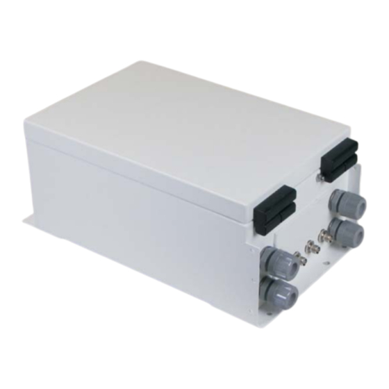
Page 83: Installing Enclosures
Installing enclosures The OmniTrax enclosure The OmniTrax enclosure is painted aluminum and includes two lockable latches on the top and two hinges on the bottom to allow the door to hang freely. There are two sets of mounting studs on the enclosure door, one for the optional 6 VDC local backup battery and the other for the optional 12 VDC auxiliary device power supply. - Page 84 Figure 49: Enclosure bottom cable entry port dimensions Note DO NOT bring AC mains power into the OmniTrax enclosure. If a local power supply is being used, it must be installed in its own weatherproof enclosure. Consult the local electrical code for information about the connection of AC mains to your power supply.
-
Page 85: System Grounding
The OmniTrax enclosure System grounding The OmniTrax processor requires a connection to a low resistance earth ground (Senstar recommends 5 or less). Install an approved ground rod or ground plate as close to the processor as possible. Use an approved ground wire to connect the ground rod to the ground lug on the processor enclosure. -
Page 86: Installing A Telecom Style Enclosure
Once the telecom enclosure is installed on the concrete base, a custom bracket is installed inside, and an OmniTrax enclosure is mounted on the bracket. Required tools and equipment •... -
Page 87: Installation Procedure For Telecom Enclosures
7. Install the ground rod/plate at the processor location. auxiliary device/self-test/ lead-in cable data cable conduit conduit (2X) drain pipe power entry conduit (1X) 20 cm (8 in.) ground level tape Figure 52: Location of conduit assemblies OmniTrax Product Guide Page 87... -
Page 88: Building The Foundation
5. Remove the tape from the ends of the PVC pipes. 6. Pull the alarm communication wiring, power cables, and auxiliary sensor/self-test wires up through the 1.9 cm (3/4 in.) diameter PVC pipes, into the enclosure. 7. Fill in the hole around the concrete base. Page 88 OmniTrax Product Guide... -
Page 89: Installing The Omnitrax Enclosure
Note The Telecom enclosure is shipped with all of the hardware that is required to install the mounting bracket and the OmniTrax enclosure. There are also four grommets provided, which are used to protect the sensor cables where they pass through the holes in the bottom of the bracket. - Page 90 Installing a telecom style enclosure enclosure mounting bracket mounting hardware hardware OmniTrax enclosure threaded enclosure mounting holes mounting bracket locking tabs locking tab slots telecom enclosure Figure 55: Mounting the bracket and OmniTrax enclosure - rear view Page 90 OmniTrax Product Guide...
-
Page 91: Indoor Wall-Mounting
4. Label all cables and wires that are being routed into the enclosure. 5. Pull the sensor cables through the conduit, to the OmniTrax enclosure. 6. Connect the ground wire to the ground stud inside the enclosure. -
Page 92: Using A Customer-Supplied Enclosure
OmniTrax weatherproof enclosure. A customer-supplied enclosure should be at least 69 cm h X 58 cm w X 20 cm d (27 in. h X 23 in. w X 8 in. d) to accommodate the OmniTrax enclosure and cable service loops. - Page 93 (27 in.) TXA RXA ground wire AC power cable DC power cable data cable A-side sensor cable B-side sensor cable NOTE: data/power cable service loops not shown. conduit concrete base Figure 58: Using a customer-supplied enclosure OmniTrax Product Guide Page 93...
-
Page 94: Replacing The Processor
Replacing the processor Replacing the processor The processor is mounted on a metal backplate, which in turn mounts inside the OmniTrax enclosure. The metal backplate fits onto four studs on the side bulkheads of the enclosure (see Figure 59: Installing the mounting plate in the enclosure). - Page 95 Figure 59: Installing the mounting plate in the enclosure OmniTrax Product Guide Page 95...
- Page 96 Replacing the processor Page 96 OmniTrax Product Guide...
-
Page 97: Installing The Sensor Cables
CAUTION The smallest allowable bend radius for all types of OmniTrax sensor cable is 15 cm (6 in.). Any tighter bend can damage the internal foil and compromise operation. -
Page 98: Preparation Of Trenches
Dig only as many trenches as can be backfilled in one day. Note Senstar recommends using a sand bedding and geotextile fabric for installations in coarse gravel. Micro-trenching is a valid installation option for soil and asphalt, and can be used provided that the trench depths and backfill requirements are maintained (e.g., the 7.5 cm stone dust layers above... -
Page 99: Trench Dimensions
There is no minus tolerance for narrow cable spacing (10 cm minimum). Senstar recommends that the installer build a tool or use a 10 cm wide device (e.g., a work boot) to ensure that the narrow cable spacing is consistent for the full length of the sensor cables. -
Page 100: Narrow Cable Spacing (Single Trench)
2. Carefully lay the sensor cables in the trench at the specified cable spacing. 3. Pull the cables taut and partially backfill the trench with 7.5 cm (3 in.) of soil as you go to hold the sensor cables in place and ensure the cable spacing remains consistent. Page 100 OmniTrax Product Guide... -
Page 101: Standard Cable Spacing (Dual Trench)
121). Next, do the cable tests (see Cable tests on page 146) and then do a sensitivity profile to verify the installation (see OmniTrax calibration - Sensitivity Profile and Transmitter Power on page 197). 5. Finish backfilling the trench. cable marker tape... -
Page 102: Burial With A Crushed Stone Topping
121). Next, do the cable tests (see Cable tests on page 146) and then do a sensitivity profile to verify the installation (see OmniTrax calibration - Sensitivity Profile and Transmitter Power on page 197). 7. Finish backfilling the trenches. 23 cm marker tape (9 in.) -
Page 103: Burial In Crushed Stone
If there is a crushed stone layer that extends to, or close to, the sensor cable burial depth, dig the trench deeper and use a stone dust or sand buffer to protect the sensor cables from the stones. After cable installation, restore the asphalt surface. OmniTrax Product Guide Page 103... - Page 104 121). Next, do the cable tests (see Cable tests on page 146) and then do a sensitivity profile to verify the installation (see OmniTrax calibration - Sensitivity Profile and Transmitter Power on page 197). 7. Backfill the trench with native soil and compact the soil.
-
Page 105: Micro-Trenching Or Boring Under A Narrow Paved Strip
If the sensor cable route crosses a narrow section of asphalt or concrete such as a sidewalk or driveway, Senstar recommends installing the sensor cables below the hard surface in a buried section of PVC conduit. The conduit requires a 19 mm (3/4 in.) internal diameter and can be a maximum 7 m (23 ft.) long. - Page 106 121). Next, do the cable tests (see Cable tests on page 146) and then do a sensitivity profile to verify the installation (see OmniTrax calibration - Sensitivity Profile and Transmitter Power on page 197). 8. Backfill the trench with native soil and compact the soil.
-
Page 107: Burial In Clay
Figure 72: Installation in moderate clay soil Burial in heavy clay soil Note If your site includes heavy clay soil, Senstar recommends engaging a Geotechnical Engineering firm to assess the soil and drainage conditions. Note Install and test one cable set, before proceeding with the full installation. - Page 108 Cable tests on page 146) and then do a sensitivity profile to verify the installation (see OmniTrax calibration - Sensitivity Profile and Transmitter Power on page 197). 8. Complete the backfilling of the trench with 7.5 cm (3 in.) of the heavy clay soil. Ensure that the native soil layer is graded to allow rainfall to run off the cable path.
-
Page 109: Preparation Of Slots In Concrete
The backer rod must extend at least 30 cm (12 in.) beyond both sides of the slot, and the backer rod must be thicker than the width of the crack or joint. See Slot dimensions on page 111. OmniTrax Product Guide Page 109... -
Page 110: Transition From A Slot To A Trench
SC2 - concrete saw capable of cutting a slot 1 cm (3/8 in.) wide by 6 cm 2 1/4 in. deep (ganged blades are recommended for single pass cutting) • air compressor and hose (the air compressor must have traps to remove moisture and oil from the air) Page 110 OmniTrax Product Guide... -
Page 111: Slot Dimensions
7. Use a drill to widen the slots for the ferrite bead’s. For OC2 cable, the beads are 2.5 cm (1 in.) in diameter. For SC2 cable the ferrite beads are 2 cm (3/4 in.) in diameter. OmniTrax Product Guide Page 111... -
Page 112: Completing The Slot Installation
- Sensitivity Profile and Transmitter Power on page 197). Joint sealant is required to seal the sensor cable in slots. Use a Senstar approved sealant or expanding foam sealant tape. Chemical sealants must be installed in dry conditions. A pump may be required for large installations. -
Page 113: Above Ground Berm Installation
2. Apply sealant to cracks and joints for at least 30 cm (12 in.) on either side of the slot. Remove excess chemical sealant from the pavement surface. 3. If desired, treat the surface along the cable path with Senstar approved waterproofing sealer. Follow the manufacturer’s instructions. - Page 114 6. Fold the geotextile fabric over the stone dust or sand and cover the fabric with a layer of crushed stone that is at least 2.5 cm (1 in.) deep. Additional crushed stone may be needed if erosion is severe. 7. Ensure that the geotextile fabric is completely covered with crushed stone. Page 114 OmniTrax Product Guide...
-
Page 115: Sensor Cable Start Points
2. Line up the two red bands on the sensor cables side-by-side at the designated start point. 3. Temporarily anchor the sensor cable at the red mark. Note Use a stake or a flag to mark the location of the red bands on the ground’s surface. OmniTrax Product Guide Page 115... - Page 116 = 6 m) align red bands at start point of detecting cable NOT TO SCALE position and secure the ferrite beads Figure 81: Laying lead-in cable Page 116 OmniTrax Product Guide...
-
Page 117: Start Point Configurations
OC2/SC2 the red marks must line up on each cable set * The 30 cm minimum separation between A-side and B-side active cables is critical to system performance. Figure 83: OC2/SC2 sensor cable start point overlap (narrow cable spacing) OmniTrax Product Guide Page 117... - Page 118 30 cm* (12 in.) minimum 8 m (26 ft.) minimum A-side * The 30 cm minimum separation between A-side and B-side active cables is critical to system performance. Figure 84: SC1 sensor cable lead-in overlap Page 118 OmniTrax Product Guide...
-
Page 119: Digging The Lead-In Cable Trench
Figure 85: OC2/SC2 sensor cable start point overlap (processor corner installation) Digging the lead-in cable trench You can dig a single trench for the two lead-in cables in a cable set. trench to processor lead-in cable Figure 86: OC2/SC2 lead-in cable using a single trench OmniTrax Product Guide Page 119... -
Page 120: Laying The Sensor Cables
Laying the sensor cables For OmniTrax sensor cables, the first 20 m (66 ft.) of cable on the reel is lead-in cable. The beginning of the detecting section is marked by red bands. Dispense the cable into the slot(s) or trench(es). -
Page 121: Installing Cable Fittings
2. Space the remaining beads 30 cm (12 in.) apart on the non-detecting cable, and secure the beads with electrical tape. Installing connectors on OC2 sensor cable To install connectors on OC2 sensor cables, you require an OmniTrax connector kit (GT0967) an OmniTrax cable tool kit (A4KT0200) and a portable heat gun. Note The OmniTrax connector kits are matched to the OC2 cables. -
Page 122: Oc2 Connector Installation Procedure
OC2 connector installation procedure Note DO NOT cut the sensor cable until you are ready to install the connector. OmniTrax requires a minimum of 6 m of lead-in cable. Part 1: Preparing OC2 sensor cable Figure 88: is a scale diagram which provides the stripping dimensions for preparing OC2 sensor cable for connector installation. - Page 123 Cable preparation dimensions 1 : 1 scale trim the drain braid to a length of 19 mm (3/4 in.) dielectric core 8 mm (5/16 in.) OmniTrax cable cross section inner black jacket outer 38 mm (1 1/2 in.) gray jacket...
-
Page 124: Part 2: Installing The Connector
4. Lift the drain braid slightly, and then fit the connector shell onto the sensor cable, so the center pin, foil and dielectric core fit smoothly into the connector shell, while the drain braid remains outside. Page 124 OmniTrax Product Guide... - Page 125 9. Slide the heatshrink over the crimp until it covers the smooth portion of the connector’s midsection. DO NOT allow the heatshrink to cover any portion of the rotating end of the connector. OmniTrax Product Guide Page 125...
-
Page 126: Installing Connectors On Sc1 And Sc2 Sensor Cable
6 m (20 ft.) of lead-in cable and there is enough lead-in cable to create a 2 m (6.5 ft.) service loop at the processor Required tools • SC1/SC2 connector tool kit (P/N A0KT1500) including: • knife • large cutting pliers • small cutting pliers Page 126 OmniTrax Product Guide... -
Page 127: Sc1 And Sc2 Cable Strip Dimensions
(see Figure 99:). Work the small cutters into the end of the cable at the score mark and push them up along the score until the jacket separates. OmniTrax Product Guide Page 127... - Page 128 (10 in.) long; shorten the remaining cable by 15 cm (6 in.) from the end of the cable • for zone bypass or cable splice applications - the longer cable should be 17 cm (6.7 in.) long; shorten the remaining cable by 6 cm (2.5 in.) from the end of the cable Page 128 OmniTrax Product Guide...
- Page 129 6 mm 8 mm (5/16 in.) 4b. Straighten the center conductor (if required) dielectric core. (1/4 in.) and trim the center conductor to 6 mm. 20 mm (25/32 in.) Figure 102: SC1/SC2 cable strip dimensions OmniTrax Product Guide Page 129...
- Page 130 Figure 105: Fitting the connector 9. Slide the crimp ring over the connector shell and drain braid until it is flush against the head of the connector. Mark the location of the drain braid on the crimp ring. Page 130 OmniTrax Product Guide...
- Page 131 Do NOT cover any portion of the rotating head of the connector. The rotating end must turn freely. Hold the cable steady until the heatshrink has completely cooled. Figure 108: Sealing the heatshrink 14. Verify the connector installation (see Cable tests on page 146). OmniTrax Product Guide Page 131...
-
Page 132: Installing Decouplers And Terminators
Figure 109: Terminating an unused cable side Unused cable side termination procedure 1. Start the UCM application and connect to the OmniTrax processor. 2. On the Cable Side Cfig tab, Select the unused Side (A or B). 3. Disable the unused Cable Side by deselecting the Enable check box (see... -
Page 133: Sealing The Heatshrink Over Decouplers/Splices
DO NOT twist or bend the sensor cable. Verify that weather sealant is oozing out at both ends. NOTE: There MUST NOT be any bubbles or air pockets in the heatshrink. heatshrink 41 cm (16 in.) Figure 110: Installing decouplers OmniTrax Product Guide Page 133... -
Page 134: Oc2/Sc2 Decoupler Installation (Method 1 - Active Loops)
Figure 112: Active-loop overlapped decoupler installation OmniTrax decouplers connect two contiguous sensor cable sets (TXA to TXB and RXA to RXB). To install decouplers using method 1: 1. Dig the trenches for the A-side cables and B-side cables and join the trenches at the specified decoupler location. -
Page 135: Oc2/Sc2 Decoupler Installation (Method 2 - Adjoining Trenches)
11. Partially backfill the trench/excavation to hold the cables in place. OC2/SC2 decoupler installation (method 2 - adjoining trenches) OmniTrax decouplers connect two contiguous sensor cable sets (TXA to TXB and RXA to RXB). To install decouplers using method 2 the trenches for the cables from one processor meet the trenches from the second processor. -
Page 136: Installing Decouplers In Hard Surface Slots
6. When completed, the cable should have a slight lazy S pattern, which provides strain relief and maintenance access. heatshrink decoupler NOT to scale (16 ft.) 10 m (33 ft.) Figure 114: Preparing cables for decouplers Page 136 OmniTrax Product Guide... -
Page 137: Installing Decouplers On Sc1 Sensor Cable
Method 1 enables power, data and processor synchronization via the sensor cables. Method 2 is best suited for a closed perimeter with a single OmniTrax processor. If method 2 is used with 2 or more processors, power and data cables are required for each processor, and synchronization must be done over the network wiring via the NIC. -
Page 138: Sc1 Decoupler Installation Procedure (Method 2 - Terminators)
NOTE: If the two sensor cables are from two processors, the processors must be synchronized via the NICs. Figure 118: Overlapping SC1 cable sets (method 2) 1. Refer to Figure 118: and the site plan to dig trenches or excavate the installation location for the decouplers. Page 138 OmniTrax Product Guide... -
Page 139: Installing Terminators - Oc2/Sc2 Sensor Cable
Installing terminators - OC2/SC2 sensor cable This procedure requires the following equipment: • OC2 connector tool kit (A4KT0200) • OC2 termination kit (A4KT1304) • SC2 connector tool kit (A0KT1500) • SC2 termination kit (A4KT1302) • heat gun OmniTrax Product Guide Page 139... - Page 140 4 m (13 ft.) overlap 4 m (13 ft.) terminator of detecting cables NOTE: Do not interleave the two sensor cable sets for narrow cable spacing single trench installations. Figure 122: Overlapping OC2/SC2 terminators Page 140 OmniTrax Product Guide...
-
Page 141: Terminators In Slots
Cable splices Terminators in slots To terminate the ends of an OmniTrax perimeter in concrete slots, you must widen the slots for approximately 6 m (19.5 ft.) to provide maintenance access and accommodate the decouplers and terminator assemblies. To make a closed perimeter in slots you overlap the two cable sets by 4 m (13 ft.) at the decouplers as indicated in... -
Page 142: Cable Splice Procedure
Cable splices Note A cable splice or bypass does not require decouplers. A cable splice requires 2 male TNCs and a female coupler. The following figures illustrate OmniTrax cable splice techniques. Figure 124: shows an OC2/SC2 cable splice and Figure 125: shows an SC1 cable splice. -
Page 143: Lead-In Cable Splices (Oc2 Sensor Cable)
Splicing in additional SC1/SC2 lead-in cable (15 m or less) To add 15 m, or less, of lead-in cable, you can splice the additional lead-in to the end of the existing lead-in cable. No other changes are required. OmniTrax Product Guide Page 143... -
Page 144: Splicing In Additional Sc1/Sc2 Lead-In Cable (Greater Than 15
(12 in.) 4 m (13 ft.) bypass start point obstacle (cable splice) detecting detecting ferrite cable cable beads to processor to decouplers bypass end point conduit through obstacle (cable splice) Figure 127: Sensor cable hardware bypass Page 144 OmniTrax Product Guide... -
Page 145: Software Bypass
Figure 128: Sensor cable software bypass 1. Complete the cable installation and perform a preliminary system calibration. 2. With the OmniTrax processor running and connected to the UCM, have a person stand on the detection field centerline at the beginning of the bypass. -
Page 146: Cable Tests
(to make short-circuit connection) Note DO NOT use high voltage cable leakage testers (meggers) on OmniTrax sensor cables, which are connected to processors, decouplers, or loopback cables. Cable pair A cable-pair consists of two separate sensor cables (TXA and TXB or RXA and RXB) connected by a decoupler. -
Page 147: Cable Set
A cable-set consists of the two sensor cables (a single cable for SC1) connected to one side of a processor (A-side or B-side, TX and RX). A cable set can be connected to another cable set through decouplers. At the end of a perimeter, OmniTrax sensor cables are connected to terminators. -
Page 148: Sensor Cable Tests
2. At the other end of the cable, measure the resistance between the connector’s center conductor and shell. • resistance = 10 or less Note For SC1/SC2 sensor cable the resistance should be approximately 3 per 100 m of cable. Page 148 OmniTrax Product Guide... -
Page 149: Insulation Resistance Test
For cable pairs with standalone decouplers the resistance should be 130 k If the resistance is different, there could be a problem with the connector installation or the decoupler. 3. Reverse the leads and repeat the measurement. OmniTrax Product Guide Page 149... -
Page 150: Leakage Resistance Test (All Cable Pairs)
4. Set the digital multimeter to measure Volts DC. Measure the voltage between the center pin and the head shell of the connector. • The voltage should be < 10 mVDC (plus or minus). If the reading is different, the sensor cable could have damage to the outer jacket. Page 150 OmniTrax Product Guide... -
Page 151: Cable-Pair Continuity Test (Network Decouplers)
Measure the resistance between the center-pin and the shield at both ends of the cable. The resistance reading should be 130 k ±5% at each end. OmniTrax Product Guide Page 151... -
Page 152: Cable-Set Continuity Test (Open Ended Perimeter)
12 VDC battery. 1. Apply power to the processor. 2. Connect the UCM to the processor. 3. Perform a centerline cable walk, while running a plot file in the UCM. Page 152 OmniTrax Product Guide... - Page 153 Cable tests A000706014 Figure 137: Typical OmniTrax plot (400 m OC2 cable) 4. Observe the recorded plot for uniform cable response. Note The maximum dynamic range over the full cable length is 20 dB. If any section of cable has a dynamic range greater than 10 dB over 10 m, adjustments must be made to the installation (e.g., add ferrite beads).
-
Page 154: Repairing Sensor Cables
Cable damage often results from digging, landscaping or other below ground construction activity. Most decoupler problems arise from moisture getting into the assembly through improperly sealed connections. Note Always retest the full length of a cable set after cable repairs are made. Page 154 OmniTrax Product Guide... -
Page 155: Ground Faults
UCM software to identify the location of cable damage • use a cable ground fault locator to determine the location of cable damage • carefully dig up the cables in the suspect location, inspect the cable and assess the level of damage OmniTrax Product Guide Page 155... -
Page 156: Replacing Decouplers
45 cm (18 in.) long Severe damage on page 159 Cable damage assessment table Required equipment • heat gun • measuring tape • shovel • garden rake • cleaning supplies - water with mild detergent, cloth, paper towels Page 156 OmniTrax Product Guide... -
Page 157: Omnitrax Oc2 Components
- for damaged sections of lead-in cable OmniTrax SC1/SC2 components • OmniTrax SC1/SC2 cable tool kit - required to replace connectors (A0KT1500) • mastic tape & vinyl or electrical tape - for superficial cable repair •... -
Page 158: Sc1 (< 1
To repair moderate damage, cut out the damaged section of cable and splice in new cable. The short OmniTrax OC2 cable repair kit (A4KT0301) includes the components required to make this repair. The following procedure applies to OC2/SC2 sensor cable. Use this procedure and refer to... -
Page 159: Severe Damage
Therefore, any section of detecting cable may be used for this purpose. The OmniTrax long cable splice kit (A4KT0302) includes two 3 m lengths of detecting sensor cable, for replacing damaged sensor cable. -
Page 160: Severe Damage (> 3M)
Note If you are using 400 m OC2 cable, and the damage is before the 300 m point, you can use a 300 m replacement cable for the repair. Page 160 OmniTrax Product Guide... - Page 161 You also need male TNC connectors, female couplers and heatshrink (46 cm for SC1, - 30 cm for SC2). Note Contact Senstar Customer Service before attempting to repair severely damaged OmniTrax sensor cable. 1. Carefully expose the damaged sensor cable’s red band at the start point.
-
Page 162: Repairing Non-Detecting Sensor Cable Damage
The second option is to splice in a replacement section of non- detecting cable. Note The OmniTrax system requires a minimum of 6 m (20 ft.) of lead-in cable. The following procedures apply to OC2/SC2 sensor cable. Use these procedures and refer to... -
Page 163: Power And Data Connections
5 Power and data connections Senstar provides two options for powering the OmniTrax sensor: • C7EM0503 - a 12 VDC power supply on a steel baseplate with no enclosure for standalone, single processor applications • A4EM0200 - a 48 VDC network power supply in a weatherproof enclosure for powering up to... -
Page 164: Sensor Cable Power Fuse Installation Rules
Replace fuses ONLY with a fuse of the same type, and rating. The OmniTrax processor includes two 5 X 20 mm 1.25 A, 250 V fast acting fuses which connect the power input connector (T3) to the sensor cables. F3 connects the input power to the RX cable,... -
Page 165: Auxiliary Power Supply Module
Note For older OmniTrax installations (before 2010) Rev E and earlier processors receiving 12 VDC local power require both F3 & F4. Fuse Usage processor connected to a 48 VDC power supply (T3) and distributing power over the RX sensor cable... - Page 166 12 VDC 48 VDC connect to power connector security device output input (T3) on OmniTrax processor connect to enclosure 48 VDC network power supply door ground stud power LEDs 48 VDC input 12 VDC output no connection...
-
Page 167: Installing The Backup Battery Kit
Installing the backup battery kit Installing the backup battery kit The OmniTrax sensor supports the addition of an optional rechargeable 6 VDC backup battery, that can be installed on the enclosure door. The battery kit includes a 6 VDC battery, a mounting bracket and hardware, a battery harness and a fuse. -
Page 168: Telecom Enclosure Wiring
3. Create a service loop by running the lead-in cables and I/O wiring one full turn around the inside of the telecom enclosure. 4. Remove the cable glands and route the I/O wiring through the appropriate cable gland, into the OmniTrax enclosure (Figure 152:). - Page 169 Telecom enclosure wiring OmniTrax SC1 lead-in cables A-side B-side NOTE: Form a 2 m (6.5 ft.) service loop by wrapping the cables once enclosure around the inside of the telecom enclosure. Strip and separate approximately 61 cm (2 ft.) of the lead in cables.
-
Page 170: Connecting The Telecom Enclosure Tamper Switch
3. Plug the other connector on the supplied wiring harness into T8, the two pin locking header, on the processor. 4. Run the two leads on the wiring harness out of the OmniTrax enclosure through the right side data cable port. -
Page 171: Processor Features
Processor features Processor features enclosure door (open at 45°) Figure 150: Processor features OmniTrax Product Guide Page 171... - Page 172 J1 - expansion header for auxiliary cards card (factory use only) (NIC, ROC, UIC) enclosure mounting holes - 1 cm (3/8 in.) X 4 lockable door latch (X 2) and 7 mm (1/4 in.) X 4 Page 172 OmniTrax Product Guide...
-
Page 173: Relay Output Alarm Communication
Relay output alarm communication Relay output alarm communication Local control mode is the default setting for the OmniTrax processor. In local control mode the inputs and outputs are controlled by the processor. The two inputs are self-test inputs. The four relays report sensor alarms, supervision alarms and processor status. -
Page 174: Relay Ratings And Settings
The contact closure inputs MUST be voltage-free. In local control mode, you connect normally open (NO) momentary switch inputs to the Aux inputs. Figure 153: illustrates the relay output configuration and the self-test input wiring for the OmniTrax processor in local control mode. Local control mode wiring connections CAUTION Disconnect the power before making the wiring connections. -
Page 175: Connection Procedure
3. Pull the power cable (if required) and ground wire into the enclosure. 4. Refer to Figure 151: Figure 153: to make the I/O wiring connections. Note Senstar recommends the use of data link lightning arrestors at any point where copper wires enter or exit a building. OmniTrax Product Guide Page 175... -
Page 176: Network Communication
Multimode fiber optic cable (820 nm) - 2.2 km (1.4 mi.) - 2 fibers per Channel - optical power budget 8 dB • Singlemode fiber optic cable (1310 nm) - 10 km (6.2 mi.) - 2 fibers per Channel - optical power budget 8 dB Page 176 OmniTrax Product Guide... -
Page 177: Relay Ratings/Settings
R1 = 5.1 k, R2 = 820 40 mV noise tolerance and 0 mV line drop Figure 155: Voltage sensing inputs CAUTION Use 1%, 1/4 W supervision resistors for OmniTrax inputs. Contact closure inputs MUST be voltage-free. OmniTrax Product Guide Page 177... - Page 178 5.1 K (NO) (NC) 5.1K supervision supervision relay (NC) relay (NO) auxiliary device auxiliary device Figure 158: Auxiliary device inputs (single resistor supervision) Page 178 OmniTrax Product Guide...
-
Page 179: Sensor Cable Lightning Protection
Figure 159: Auxiliary device inputs (unsupervised) Sensor cable lightning protection For increased lightning protection, Senstar recommends the installation of sensor cable lightning arrestors (A4KT1000 - includes 4 arrestors, A4KT1001 - includes 2 arrestors) which connect to the bulkhead TNCs on the enclosure. The sensor cables are then connected to the lightning arrestors. - Page 180 Tighten the set screw to secure the ground strap ground strap. twisted, folded and passed through lug tighten set screw ground strap Figure 160: Preparing the lightning arrestors for installation Page 180 OmniTrax Product Guide...
-
Page 181: Replacing The Gas Capsule
CAUTION Use only Senstar P/N GE0507 - GDT/90V replacement gas capsules and holders. 1. Label and disconnect the sensor cables. -
Page 182: Installing Auxiliary Cards
9. Reconnect the sensor cables to the lightning arrestors. Installing auxiliary cards There are three auxiliary cards available for the OmniTrax system. The Network Interface card is required for all processors that communicate via the Silver Network. The Relay Output card (ROC) provides an additional 8 relay outputs to the processor. -
Page 183: Auxiliary Card Installation Procedure
Figure 163: Figure 164:. Network Interface card You require a network interface card (NIC) if your OmniTrax processor will communicate on Senstar’s Silver Network. There are five variants of the NIC, each specific to the network transmission media (P/N 00BA03xx): •... - Page 184 TXB- TXB- GND* GND* RXA+ RXA- TXA+ * Use single point grounding, connect one end of the shield, trim back the other end and TXA- leave it disconnected. GND* Figure 163: Network Interface card variants Page 184 OmniTrax Product Guide...
-
Page 185: Relay Output Card
Figure 164: Relay output card connection details Note You make OmniTrax I/O wiring connections on removable terminal blocks. The screw terminals accept wire sizes from 12 to 24 AWG, with a 6 mm (1/4 in.) strip length. Remove the terminal blocks from the auxiliary cards before connecting the wiring. -
Page 186: Universal Input Card
Installing auxiliary cards Universal Input card INPUT 5 INPUT 6 INPUT 7 INPUT 8 INPUT 1 INPUT 2 INPUT 3 INPUT 4 top tier bottom tier Figure 165: Universal input card connection details Page 186 OmniTrax Product Guide... -
Page 187: Calibration & Setup
To calibrate the OmniTrax sensor, setup the initial configuration parameters and then run a sensitivity profile. You can also fine tune the OmniTrax sensor for your site conditions by adjusting the processor’s configuration parameters. The following table includes the OmniTrax configuration parameters along with a short description and page reference. - Page 188 Select the Delete button to merge the currently selected segment with the preceding segment Profile button The OmniTrax Sensitivity Profile records the response magnitude for each meter of sensor cable based on a valid target moving lengthwise at the center of the detection field (see...
- Page 189 Network Manager mode. The following procedure is an overview of the OmniTrax calibration routine. Each step is covered in detail further in this chapter. 1. Connect a computer running the UCM to T2 on the processor.
-
Page 190: The Universal Configuration Module
OmniTrax system. The UCM communicates with the OmniTrax processor directly through a local USB connection to T2 on the processor, or remotely via the Silver Network Manager. When you start the UCM, a window displays that enables you to specify the device to which you are connecting. - Page 191 The Universal Configuration Module When you select the Connect button, the main UCM screen for the OmniTrax processor displays. details on connected processor screen selection tabs (display processor configuration screens) event log displays the 100 most recent events since this UCM connection was established...
-
Page 192: Calibration
Calibration Calibration Calibrate the OmniTrax sensor to meet the site-specific detection requirements. Note Senstar recommends that the initial calibration of the OmniTrax processor be performed using a direct USB connection between the processor and the UCM computer. An enclosure tamper condition must be active to establish a direct USB connection to the OmniTrax processor (i.e., enclosure door opened). -
Page 193: Specifying The Processor Synchronization
Specifying the processor synchronization Processor synchronization prevents mutual interference between processors that are connected through decouplers. All OmniTrax processors generate a sync message. However, when multiple processors are connected through decouplers, only one of the processors may initiate the synchronization cycle. This processor is referred to as the sync master. The other processors receive the sync message, re-sync accordingly, and then send their sync message on to the next processor. -
Page 194: Mutual Interference
(A-side and B-side) - Duty Cycle and Coding. Transmitter Duty Cycle: Duty Cycle refers to the time period that the OmniTrax RF transmitter is ON and OFF. There are two Duty Cycle settings, 100% in which the transmitter is always ON, and 50% in which the transmitter is ON for 25 ms then OFF for 25 ms in a repeating pattern. -
Page 195: Setting The Initial Configuration Parameters
Setting the initial configuration parameters Note You must set the initial configuration parameters before calibrating the OmniTrax sensor. If you make changes to these parameters after the calibration is complete, you must repeat the calibration procedure. Note If there is an unused cable side on a processor, you must deselect (uncheck) the Enable check box for the unused cable side. -
Page 196: Using The Optional Local Backup Battery
2. If this processor includes an auxiliary option card, use the Aux Option Card selection arrow to specify the type of card (Input OR Output). 3. Save the UCM file and download the configuration changes to the processor. Page 196 OmniTrax Product Guide... -
Page 197: Omnitrax Calibration - Sensitivity Profile And Transmitter Power
Figure 175: Calibration flow chart The OmniTrax Sensitivity Profile provides a peak response for each meter of detecting sensor cable, based on a valid target moving along the centerline of the detection field. The Sensitivity Profile created during this procedure becomes the baseline for setting the cable margin for the full length of detecting cable. -
Page 198: Recording The Sensitivity Profile
10 m past the decouplers. 2. Select the Record button and have the walker perform the centerline cable walk over the full length of the detecting sensor cable. Figure 176: Starting the profile Page 198 OmniTrax Product Guide... -
Page 199: Editing The Sensitivity Profile
B-side sensor cables by 8 m (4 m from each cable) enables this section of the Sensitivity Profile to be edited to exclude the low spot. Figure 178: illustrates a raw Sensitivity Profile and the same Profile after editing. OmniTrax Product Guide Page 199... - Page 200 Otherwise, you will have to repeat the centerline cable walk to create a new Sensitivity Profile. CAUTION Contact Senstar Customer Service for application advice if the profile editing results in any areas of the perimeter that lack the required detection sensitivity.
- Page 201 (the test subject should be the same person who did the centerline cable walk). While making the crossings, record an OmniTrax response plot on the UCM. You then review the recorded response plot to determine a safe location for profile editing.
- Page 202 5. Once the walker passes the 150 m point select the Stop button. 6. Select the Update button to add the new Profile data to the existing Profile. CAUTION Contact Senstar Customer Service before using the Block Adjust, Bridge or Updated Profile functions. Page 202...
-
Page 203: Setting The Transmitter Power Level
If you are recalibrating a section of the cable use the Transmitter Power level that was indicated during the full calibration. Do not change the Transmitter Power level unless you are recalibrating the full length of detecting cable. OmniTrax Product Guide Page 203... -
Page 204: Setup
After initial calibration, perform multiple crossing tests to verify that the system meets your detection requirements. Once your OmniTrax processor is calibrated, you can setup the system for: • cable margin (alarm threshold) •... -
Page 205: Cable Margin Procedure
Defining the cable segments and alarm zones Each OmniTrax cable set can be divided into as many as 50 cable segments (100 per processor). The defined cable segments can then be assigned to as many as 50 distinct alarm zones per processor. -
Page 206: Defining The Lead-In Cable Segment As Non-Detecting
The detecting cable segment is divided into two equal portions, one gray and one white. 3. Drag the zone boundary to the appropriate point of the detecting cable (refer to the site plan). 4. Left-click on the gray detecting cable section of the profile. Page 206 OmniTrax Product Guide... -
Page 207: Setting The Cable Segment Margins
Repeat this procedure to set a cable segment margin for other segments (or Zones) as specified in the site plan. Note Cable segment margins should be set only for zones which require a higher, or lower, level of sensitivity. OmniTrax Product Guide Page 207... -
Page 208: Target Speed Settings
The high speed slider increases or decreases the system’s response to a fast moving target. Note If you adjust the target speed sliders, move the slider one level at a time and retest the cable. 2. Save the UCM file and download the configuration data to the processor. Page 208 OmniTrax Product Guide... -
Page 209: Stc Filter Settings
You configure the processor’s inputs and outputs (I/O) via the UCM, under the Aux Cfig tab. You must specify the Aux Control mode and whether you have an Aux Option Card installed before you configure the I/O. Figure 188: illustrates the Aux Cfig tab on the OmniTrax UCM window. OmniTrax Product Guide Page 209... - Page 210 First you select an input, then you configure indicated beside the parameter selection drop the selected input’s parameters. down inputs 1 and 2 on the OmniTrax processor Applicable Range is displayed beside the inputs Opt1 to Opt8 on the auxiliary input card parameter selection drop down...
-
Page 211: Auxiliary (Aux) Inputs
Fail Safe - specified relay activates to signal all input power has failed and the processor is not operational I/O configuration parameters Auxiliary (AUX) inputs The two AUX inputs on the OmniTrax processor are voltage sensing inputs (see Figure 155:). The processor determines an input’s status by comparing the input’s voltage with the defined state’s... -
Page 212: Local Control Mode
Filter Window parameter (default = 250 ms). Remote control mode In remote control mode, the two AUX I/Ps on the OmniTrax processor, and the eight inputs on the UIC (if installed) serve as auxiliary device inputs to the host security management system. The inputs are available for reporting the status of other security devices. -
Page 213: Input Configuration Procedure
7. Set the Line Drop, if applicable. 8. Set the Filter Window. 9. Repeat this procedure if there is a second connected input (Aux2). 10. Save the UCM configuration file and download the configuration changes to the processor. OmniTrax Product Guide Page 213... -
Page 214: Output Relay Setup
Output relay setup Local control mode In local control mode, the four on-board relays are controlled by the OmniTrax processor to report alarm and supervision conditions. The relays remain active for an event’s duration or for the selectable relay Active Time, whichever is longer. The conditions under which each relay will activate can be configured by the user via the UCM. -
Page 215: Specify The Network Connection And Synchronization Scheme
Specify the network connection and synchronization scheme Use the UCM to select your network connection type from the Network Configuration/ Connection drop down menu (see OmniTrax network communication and synchronization options on page 225). 1. Select the Network Cfig tab on the main UCM window. -
Page 216: Clutter Display
You should review the current clutter level regularly, and reset the historic clutter level. This will prevent supervision alarms resulting from changing ground conditions over time, rather than cable faults. For clutter supervision, an alarm should be triggered only by a sudden sharp increase in the clutter level. Page 216 OmniTrax Product Guide... -
Page 217: Historic Clutter
Figure 191: OmniTrax clutter display Historic clutter Note The Historic clutter level is used by all types of OmniTrax cable supervision. When you first setup and calibrate the OmniTrax processor, save a UCM file, which includes the original level of clutter. -
Page 218: Locating The Detection Field Centerline
For this procedure, you will require an accurate site plan, two way radios, marker paint, a walker and a maintenance technician running an OmniTrax magnitude response plot on the UCM. 1. Use the site plan to determine the start point of the detection zone. -
Page 219: The Silver Network
The Silver Network Silver Network overview The Silver Network provides the communication backbone for Senstar’s line of perimeter intrusion detection sensors and I/O devices. The Silver Network implements a point-to-point communication system using a ring topology. Processor 4 Processor 5... -
Page 220: Network Components
Network components fiber). In addition, the OmniTrax processor can use its sensor cables to carry both Silver Network data and 48 VDC network power between processors. Repeaters are available for the supported transmission media (excluding OmniTrax sensor cables) to double the maximum separation distance between network devices. -
Page 221: Network Interface Card
OmniTrax processors, which communicate over the sensor cables require an NIC. Do not use a mixed media NIC to connect an NIU to an OmniTrax processor, which will communicate with other processors over the sensor cables. In this case, use an 01, 02 or 03 variant (single media NIC). -
Page 222: Omnitrax Sensor
Network components OmniTrax sensor The OmniTrax sensor is a covert, high-security system, that uses a set of buried cables to create a volumetric detection field around a perimeter. Each processor can monitor two independent sensor cable sets, each with up to 400 m of detecting cable. OmniTrax provides precise target location, and each processor supports up to 50 distinct software-defined sensor zones. -
Page 223: Fiberpatrol Fp400 Sensor
Silver devices. In NM Mode, the Silver devices do not require a connection to a PC running Silver Network Manager software. The supported Silver devices include OmniTrax, FlexZone, FlexPS, UltraWave, XField and XField LT. Sensor alarms and supervision conditions are assigned to UltraLink I/O outputs (relay or open collector). When an alarm occurs on a connected sensor, the corresponding UltraLink I/O output is activated. -
Page 224: Universal Configuration Module
Universal Configuration Module The Universal Configuration Module (UCM) is a Windows-based software application that performs the configuration and calibration functions for OmniTrax and all other Silver Network compatible devices. The UCM also provides diagnostic, monitoring and maintenance functions for each device. The UCM can reside on the same PC as the NM, or can be located on a separate computer. -
Page 225: Network Configuration
Response time - 1.0 second, or less from alarm source to Network Manager (per loop) • Transmission media/maximum separation distances between processors: • OmniTrax OC2 sensor cable - approximately 800 m (2625 ft.) for continuous detection • OmniTrax SC1/SC2 sensor cable - approximately 400 m (1312 ft.) for continuous detection •... - Page 226 The arrows indicate the direction of data flow: EIA-422 Sensor Cable Fiber Optic TXA+ RXB+ TXA- RXB- RXA+ TXB+ RXA- TXB- (use single point grounding, connect only one side of shield) Figure 194: Silver Network data flow diagrams Page 226 OmniTrax Product Guide...
- Page 227 OmniTrax 1 is isolated and does not require synchronization with the other processors. OmniTrax 11 is the sync master for OmniTrax processors 2, 3, 4, 8, 9 and 10. OmniTrax 12 and 13 are also isolated from the other processors and need only be synchronized as a pair with OmniTrax 13 serving as the sync master for OmniTrax 12.
-
Page 228: Connection Diagrams
1 2 3 4 5 1 2 3 4 5 lightning lightning arrestors arrestors shield shield to Network Manager shield shield via EIA-232 OR Ethernet OR USB Figure 196: OmniTrax Silver Network wiring - EIA-422 & sensor cables Page 228 OmniTrax Product Guide... - Page 229 TXA RXA to Network Manager via EIA-232 OR Ethernet OR USB Figure 197: OmniTrax Silver Network wiring - fiber optic & sensor cables The following figures illustrate Silver Networks using the recommended closed loop configurations. NOTE: The security management system and...
- Page 230 Each loop requires its own NIU and the Network Manager PC must support the connection of four NIUs. Each NIU must use the same communication option to connect to the NM Figure 201: illustrates a Silver Network using four independent communication loops. Page 230 OmniTrax Product Guide...
- Page 231 Processor 10 Processor 17 Processor 22 Processor 16 Loop 4 Loop 3 Processor 11 Processor 15 Processor 18 Processor 21 Processor 14 Processor 13 Processor 20 Processor 12 Processor 19 Figure 201: Four loop configuration OmniTrax Product Guide Page 231...
-
Page 232: Redundant Configuration
Processor 8 security security management management system system Processor 3 Processor 9 Network Network Manager Manager Processor 2 Processor 10 Network Interface Unit Network Interface Unit Processor 1 Processor n Figure 202: Redundant network setup Page 232 OmniTrax Product Guide... -
Page 233: Silver Network Point Assignments
11 to 60 Cable zone #n (bit 0 alarm, bit 1 bit 1 supervision) unused) Option card input Opt4 (bit 0 alarm, bit 1 supervision) OmniTrax output point mapping (controls) Point Description Point Description Processor relay 1 Option card relay Opt3... -
Page 234: Starnet 1000 Point Assignments
Side B interference fault +5V/-5V rail fault Point Description Sensor alarms 51 to 100 Zone 1 to Zone 50 sensor alarms OmniTrax 0utput point mapping (controls) Point Description Point Description Aux control 1 (Processor relay 1) Aux control 7 (Output card relay 3) -
Page 235: System Component List
A4EM0301 replacement OmniTrax processor on metal backplate mounting plate OmniTrax processor auxiliary cards (an NIC is required for each processor using network communications) Network Interface 00BA0301 Fiber optic NIC, mounts on processor, supports two multi-mode 62.5/125 Card (multi-mode... - Page 236 12 VDC auxiliary 00EM0400 Auxiliary device power supply module, 12 VDC @ 150 mA max. regulated device power output power, mounts on door inside OmniTrax enclosure, for use with supply module processors receiving 48 VDC network power optional 6 VDC...
- Page 237 50 m (164 ft.) OC2 non-detecting cable (lead-in) cable OC2 non-detecting A4CA0303 100 m (328 ft.) OC2 non-detecting cable (lead-in) cable Ferrite beads (SC1) A3KT0300 Single cable ferrite bead kit (50) for SC1 sensor cable OmniTrax Product Guide Page 237...
- Page 238 NIU interfaces between Silver Network based security transponders and Unit - single-mode Windows based head end Network Manager 00FG0200 Silver Network manager software application, controls and communicates Software with Silver Network based security transponders, communicates with Windows based display and control system Page 238 OmniTrax Product Guide...
- Page 239 Silver Network repeater EIA-422 to EIA-422 repeater Silver Network 00EM0303 Silver Network repeater multi-mode fiber to EIA-422 repeater Tape X0191 Mastic tape Tape X0190 Vinyl tape Tape A4SP0100 Underground warning tape Manuals A4DA0120 OmniTrax documentation CD OmniTrax Product Guide Page 239...
-
Page 240: Supplier's Information
1/2 hour to 3 days. It has been used extensively in less demanding applications. 3M 5000 traffic loop detector sealant, comes in 1 liter sausages, 12 per case, requires pumping equipment Page 240 OmniTrax Product Guide... -
Page 241: Other Sealant Suppliers
Consult the sealant manufacturer or local supplier for recommendations. They may also rent equipment for application or suggest a local installer. For smaller jobs requiring only several feet, the use of caulking guns or pails may be most suitable. For intermediate sizes, for example a OmniTrax Product Guide Page 241... -
Page 242: Backer Rod
Considerations are alcohol carrier materials dry quickly in windy conditions, and water-based materials are affected by humidity while drying. Some materials and sources of supply are: Page 242 OmniTrax Product Guide... -
Page 243: Metal Foil
Tel. (402) 434-6981 Metal foil Note Any foil used must be rated for direct burial. For information on sources of metal foil contact Senstar Corporation. Terra-Tape Sentry Line 620 24 in wide x 1000 ft. Red, no imprint, no logos Part no. - Page 244 Supplier’s information Page 244 OmniTrax Product Guide...
-
Page 245: Specifications
20 dB per cable set range • CSA type 4 (equivalent to NEMA-4/IP66) painted aluminum Enclosure options enclosure, lockable, with tamper switch • Telecom style pedestal enclosure (IP33), light green enamel on steel • 32.125 MHz Operating frequency OmniTrax Product Guide Page 245... - Page 246 ROC per processor, cannot be used with UIC) • Universal Input Card (UIC) - provides 8 additional inputs (one ROC per processor, cannot be used with UIC) • NOTE - auxiliary card power consumption is included in the processor’s rating Page 246 OmniTrax Product Guide...
- Page 247 • 115/230 VAC, 60/50 Hz Power input • 12 VDC, 80 W Power output • 00EM0400 Part number • 48 VDC Power input • Power consumption • 12 VDC @ 150 mA maximum Power output OmniTrax Product Guide Page 247...
- Page 248 Network data terminations • three variants - EIA-422, multi-mode fiber, EIA-422 and multi-mode Network repeaters fiber • double the maximum separation distance between devices • 12 to 48 VDC power input, 2 W max. consumption Page 248 OmniTrax Product Guide...
-
Page 249: Nm Mode
Silver devices. In NM Mode, the Silver devices do not require a connection to a PC running Silver Network Manager software. The supported Silver devices include OmniTrax, FlexZone, Senstar LM100, UltraWave, FlexPS, XField and XField LT. Sensor alarms and supervision conditions are assigned to UltraLink I/O outputs (relay or open collector). -
Page 250: Ucm Configuration
Silver Loop. A temporary break in the NM Mode Silver Loop network is also required. Figure 203: NM Mode block diagram UCM configuration To use UltraLink modular I/O system outputs to report OmniTrax alarm and supervision conditions establish a UCM connection to the OmniTrax processor. Note Refer to the UltraLink Modular I/O system instruction sheet and the UCM help file for additional details on NM Mode operation. - Page 251 Segment detects a sensor alarm the processor’s 4 onboard relays are also available in NM Mode Figure 205: Selecting the UltraLink I/O outputs for Zone alarms OmniTrax Product Guide Page 251...
- Page 252 Page 252 OmniTrax Product Guide...
Need help?
Do you have a question about the OmniTrax and is the answer not in the manual?
Questions and answers