Haier HBU-18HF03 Manual
Single split r22
Hide thumbs
Also See for HBU-18HF03:
- Operating & installation manual (25 pages) ,
- Installation instructions manual (15 pages)
Table of Contents
Advertisement
Part 1 General Information..............................................................................1
Part 2 Indoor Units.........................................................................................8
4-way Cassette indoor unit(HBU-18~HBU-42).................................................9
Convertible indoor unit (HCFU-18~HCFU-42).................................................37
Duct indoor unit (HDU-18~HDU-50 and AD96NAHAEA).................................. 68
Cabinet indoor unit (HPU-42~HPU-48 and AP96NACAEA)...............................98
Part 3 Outdoor Units.....................................................................................122
Part 4 Electrical Control.................................................................................190
Part 5 Maintenance.......................................................................................240
Part 6 Control Devices................................................................................ 252
Appendix-Control data....................................................................................282
Contents
Single Split R22
..
Advertisement
Chapters
Table of Contents

Related Manuals for Haier HBU-18HF03


Summary of Contents for Haier HBU-18HF03
-
Page 1: Table Of Contents
Single Split R22 Contents Part 1 General Information……………………………………………………………………1 Part 2 Indoor Units……………………………………………………………………………..8 4-way Cassette indoor unit(HBU-18~HBU-42)………………………………………….9 Convertible indoor unit (HCFU-18~HCFU-42)…………………………………….……37 Duct indoor unit (HDU-18~HDU-50 and AD96NAHAEA)……………………………. 68 Cabinet indoor unit (HPU-42~HPU-48 and AP96NACAEA)………………………….98 Part 3 Outdoor Units………………………………………………………………………….122 Part 4 Electrical Control………………………………………………………………..190 Part 5 Maintenance…………………………………………………………………..……….240 Part 6 Control Devices…………………………………………………………………….. - Page 2 Single Split R22 Part 1 General information 1. Nomenclature……………………………………………………………………..…2 2. External apperance…………………………………..........3 3. Operation temperature range……………………………………………..…….5 4. Function………………………………………………………………………....…6...
-
Page 3: Nomenclature
Power supply type: 03 stands for 200-220V, 50Hz Design sequence C: cooling; H: heating Cooling capacity: 42=42000BTU/h U: single split unit Product type : “B” stands for cassette type, “CF” stands for convertible type, ”D” stands for duct, ”P” stands for cabinet system, Haier Brand Air Conditioner... -
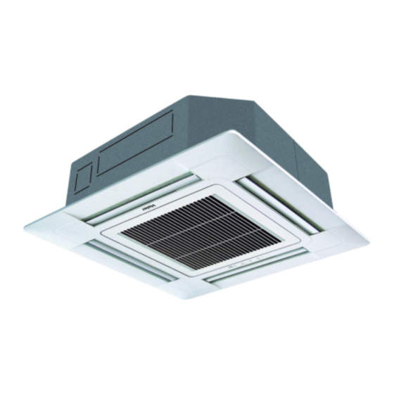
Page 4: External Apperance
External apperance 2. External appearance... - Page 5 External apperance...
-
Page 6: Operation Temperature Range
Operating temperature range 3. Operating temperature range 3.1 For HDU-50HT03/H (T3 climate) Temp. Mode Rated Maximum Minimum DB ℃ Indoor WB ℃ Cooling DB ℃ Outdoor WB ℃ DB ℃ Indoor WB ℃ Heating 14.5 DB ℃ Outdoor WB ℃ 3.2 For other units Temp. - Page 7 Functions 4. Functions 3 minutes protection 4-way airflow The 3 minutes protection of the The front air deflectors are adjustable compressor can avoid some for horizontal or vertical air- damages to it and makes the conditioning, The airflow can be compressor have a longer life.
-
Page 8: Part 2 Indoor Units
Indoor units Part 2 Indoor Units 4-way Cassette indoor unit (HBU-18~HBU-42)…………………………………………..........9 Convertible indoor unit (HCFU-18~HCFU-42)………………………………………………………………..…. 36 Duct indoor unit (HDU-18~HDU-50 and AD96NAHAEA)…………………………………………………………………..…….. 67 Cabinet indoor unit (HPU-42~HPU-48 and AP96NACAEA)………………………………………………………………………..97... -
Page 9: 4-Way Cassette Indoor Unit(Hbu-18~Hbu-42)
4-way Cassette type 4-way Cassette indoor unit (HBU-42~HBU-48) 1. Features………………………………………………………… 10 2. Specifications………………………………………………… 12 3. Dimensions…………………………………......24 4. Part name…………………………………………………….. 27 5. Installation……………………………………………………. 28... - Page 10 Features 1. Features New particular design: The new designed panel, smaller and universal. Harmony with the environment. Both 700mm×700mm and 950mm×950mm panels have a uniform style and standard apperance. 24cm 24.5cm 700mm 240mm/ 290mm For the unit with PB-950IA 700mm For the unit with PB-700IA For the unit with PB-950JA Quiet operation...
- Page 11 Features Antifouling and movable baffle The movable baffle has antifouling design and can effectively control the airflow and air direction. It is clean to use without polluting the ceiling. It has standard long acting filter screen to make the cleaning time largely extended.
-
Page 12: Function
Specifications 2. Specifications item Model HBU-18CF03 cooling heating Function 17000 Capacity BTU/h Capacity Sensible heat ratio 1780 Total power input 2400 Max. power input 2.81 EER or COP Dehumidifying capacity 10‐³×m³/h 3×2.5mm2 Power cable section Signal cable section 3×2.0mm2 Connecting cable section Power source N, V, Hz... - Page 13 Specifications HBU-18HF03 item Model cooling heating Function 17000 18700 Capacity BTU/h Capacity Sensible heat ratio 1780 1900 Total power input 2400 2400 Max. power input 2.81 2.89 EER or COP Dehumidifying capacity 10‐³×m³/h 3×2.5mm2 Power cable section Signal cable section 3×2.0mm2+2×0.75mm2...
- Page 14 Specifications HBU-28CF03 item Model cooling heating Function 24000 Capacity BTU/h Capacity Sensible heat ratio 2850 Total power input 3600 Max. power input 2.49 EER or COP 3.0 Dehumidifying capacity 10‐³×m³/h 3G×4.0mm2 Power cable section Signal cable section 4×0.75mm2 Connecting cable section 1,220-230,50 Power source...
- Page 15 Specifications HBU-28HF03 item Model cooling heating Function 24000 26600 Capacity BTU/h Capacity Sensible heat ratio 2700 3000 Total power input 3500 Max. power input 3400 2.63 EER or COP Dehumidifying capacity 10‐³×m³/h 3G×4.0mm2 Power cable section Signal cable section 6×0.75mm2 Connecting cable section 1,220-230,50...
- Page 16 Specifications item Model HBU-28CH03 cooling heating Function 24000 —— Capacity BTU/h —— Capacity Total power input 2700 —— Max. power input 3400 —— EER or COP 2.63 —— Dehumidifying capacity 10‐³×m³/h Power cable section 3G 4.0mm2 Signal cable section 4G 0.75mm2 Connecting cable section Power source...
- Page 17 Specifications item Model HBU-28HH03 Function cooling heating Capacity BTU/h 24000 25000 Capacity Total power input 2700 2700 Max. power input 3200 3200 EER or COP 2.63 2.77 Dehumidifying capacity 10‐³×m³/h Power cable section 3G*4.0mm² Signal cable section 6G*0.75mm² Connecting cable section Power source N, V, Hz...
- Page 18 Specifications HBU-42CF03 item Model cooling heating Function 41000 ----- Capacity BTU/h ----- Capacity ----- Sensible heat ratio 4800 ----- Total power input Max. power input 5500 ----- 2.55 ----- EER or COP Dehumidifying capacity 10‐³×m³/h Power cable section 5×2.5mm Signal cable section 4×0.75mm Connecting cable...
- Page 19 Specifications HBU-42HF03 item Model cooling heating Function 41000 42600 Capacity BTU/h 12.5 Capacity Sensible heat ratio 4500 4200 Total power input 5600 Max. power input 5600 2.67 2.98 EER or COP Dehumidifying capacity 10‐³×m³/h 5×2.5mm2 Power cable section Signal cable section 6×0.75mm2 Connecting cable...
- Page 20 Specifications item Model HBU-42CH03 Function cooling heating Capacity BTU/h 41000 —— Capacity —— Total power input 4700 —— Max. power input 5500 —— EER or COP 2.55 —— Dehumidifying capacity 10‐³×m³/h Power cable section 5G*2.5mm² Signal cable section 4G*0.75mm² Connecting cable section Power source N, V, Hz...
- Page 21 Specifications item Model HBU-42CI03 Function cooling heating Capacity BTU/h 41000 —— Capacity —— Total power input 4500 —— Max. power input 5500 —— EER or COP 2.67 —— Dehumidifying capacity 10‐³×m³/h Power cable section 5G*2.5mm2 Signal cable section 4G*0.75mm2 Connecting cable section Power source N, V, Hz...
- Page 22 Specifications item Model HBU-42HI03 Function cooling heating Capacity BTU/h 41000 44000 Capacity Total power input 4500 4700 Max. power input 5500 5300 EER or COP 2.67 2.77 Dehumidifying capacity 10‐³×m³/h Power cable section 5G*2.5mm2 Signal cable section 4G*0.75mm2 Connecting cable section Power source N, V, Hz...
- Page 23 Specifications Installation state: the unit should be placed on the flat floor or be mounted in horizontal direction. Testing method: built-in-ceiling unit: outdoor unit: 1.air outlet from side: the noise level is the average sound pressure level measured from front, left, right directions. 2.air outlet from top: the noise level is the average sound pressure level measured from front, back, left, right directions.
- Page 24 Dimension 3. Dimension 3.1 HBU-18CF03, HBU-18HF03 (used for the unit with PB-700IA panel) 1000 over -24-...
- Page 25 Dimension 3.2 HBU-28/42CF03, HBU-28/42HF03(with PB-950IA panel), HBU-28CH03 and HBU-28HH03 (with PB-950JA panel) 1000 over -25-...
- Page 26 Dimension 3.3 HBU-42CH03, HBU-42CI03, HBU-42HI03 (used for the unit with new PB-950JA panel) 1000 over -26-...
- Page 27 Part name 4. Part name For HBU-18CF03, HBU-18HF03 For HBU-28/42CF03 and HBU-28/42HF03 HBU-28/42CH03, HBU-28HH03, HBU-42CI03, HBU-42HI03 -27-...
- Page 28 Installation 5. Installation Cautions for the installation personnel -28-...
- Page 29 Installation Before installation <Don't discard any accessories until comp> Selection of installation place Preparation for the installation <Installation example> -29-...
- Page 30 Installation Installation of indoor unit In the case of new ceiling < After installation on the ceiling > In the case of ceiling already exists -30-...
- Page 31 Installation Refrigerant piping As for outdoor piping, please refer to installation of outdoor unit Table 1 Installation of water drainage pipe Cautions for the drain water lifting pipe -31-...
- Page 32 Installation + , + , + , + , After wiring When wiring is not complete -32-...
- Page 33 Installation Wiring -33-...
- Page 34 Installation << WARNING Wiring example Note: Installation of ornament panel Cautions for the installation Accessory Pad 1. Prepare ornament panel Handling of ornament panel Remove air inlet grill from ornament panel: Remove cover plate at corner 2. Mounting on high ceiling -34-...
- Page 35 Installation 3. Install ornament panel on indoor unit. 4. Installation of inlet grill and cover plate When installing inlet grill, take care not to twist wiring of swing flap motor. -35-...
- Page 36 Installation Pay special care to the following and check after installation Unproper installation may cause Check Item to the checked ATTENTION: after finishing installation,confirm no refrigerant leakage. -36-...
-
Page 37: Convertible Indoor Unit (Hcfu-18~Hcfu-42)
Convertible type Convertible indoor unit (HCFU-18~HCFU-42) 1. Features…………………………………………………….38 2. Specifications……………………………………………..40 3. Dimensions………………………………………………..49 4. Part name………………………………………………….51 5. Installation………………………………………………...52 5.1 For series28..………………….....52 5.2 For series 42......………....58 -37-... -
Page 38: Features
Features 1. Feafures Streamline appearance The unit adopts streamline design that makes it so compact and has a popular appearance. So it can add elegance to any style of interior. Optional installation mode The indoor unit can be installed on the floor or to the ceiling. It always greatly decreases the space needed and also it can provide the same comfort to us. - Page 39 Features Ultra-thin unit body, only thick 199 mm The convertible indoor unit adopts a double drain pan design, the unit body is very thin, only 199 mm. It is beautiful and elegant and the most important-space saving (for model 12, 18, 24). Long-life and high efficiency air purify filter The units adopts high efficiency air purify filter, greatly improve the room air quality;...
-
Page 40: Specifications
Specifications 2. Specifications item Model HCFU-18CF03 Function cooling heating Capacity BTU/h 16500 ----- Capacity 4.83 ----- Sensible heat ratio Total power input 2000 ----- Max. power input ----- 2500 ----- EER or COP Dehumidifying capacity 10‐³×m³/h Power cable section 3G×2.5mm Signal cable section 3G×2.0mm... - Page 41 Specifications item Model HCFU-18HF03 cooling heating Function Capacity BTU/h 16500 18000 Capacity 4.83 5.275 Sensible heat ratio Total power input 2000 1800 Max. power input 2500 2400 2.93 EER or COP Dehumidifying capacity 10‐³×m³/h Power cable section 3G×2.5mm Signal cable section 3×2.0mm +2×0.75mm...
- Page 42 Specifications item Model HCFU-28CF03 cooling heating Function Capacity BTU/h 24000 ----- Capacity ----- Sensible heat ratio Total power input 2800 ----- Max. power input 3400 ----- 2.54 ----- EER or COP Dehumidifying capacity 10‐³×m³/h Power cable section 3G×4.0mm Signal cable section 4G×0.75mm Connecting cable...
- Page 43 Specifications item Model HCFU-28HF03 cooling heating Function Capacity BTU/h 24000 26000 Capacity Sensible heat ratio Total power input 2850 2800 Max. power input 3500 3400 2.54 EER or COP Dehumidifying capacity 10‐³×m³/h Power cable section 3G×4.0mm Signal cable section 6G×0.75mm Connecting cable section Power source...
- Page 44 Specifications item Model HCFU-42CF03 cooling heating Function Capacity BTU/h 42000 ----- Capacity 12.3 ----- Sensible heat ratio Total power input 4600 ----- Max. power input ----- 5700 2.67 ----- EER or COP Dehumidifying capacity 10‐³×m³/h Power cable section 5G×2.5mm Signal cable section 4G×0.75mm Connecting cable...
- Page 45 Specifications item Model HCFU-42HF03 cooling heating Function Capacity BTU/h 44000 48000 Capacity 12.9 14060 Sensible heat ratio Total power input 4600 4600 Max. power input 5220 5540 3.06 EER or COP Dehumidifying capacity 10‐³×m³/h Power cable section 5G×2.5mm Signal cable section 6G×0.75mm Connecting cable...
- Page 46 Specifications item Model HCFU-42CH03 cooling heating Function Capacity BTU/h 42000 ----- Capacity 12.3 ----- Sensible heat ratio Total power input 4600 ----- Max. power input ----- 5700 2.67 ----- EER or COP Dehumidifying capacity 10‐³×m³/h Power cable section 5G×2.5mm Signal cable section 4G×0.75mm Connecting cable...
- Page 47 Specifications item Model HCFU-42HK03 cooling heating Function Capacity BTU/h 42000 48000 Capacity 12.5 14.06 Sensible heat ratio Total power input 4600 4600 Max. power input 5540 5220 3.06 EER or COP Dehumidifying capacity 10‐³×m³/h Power cable section 5G×2.5mm Signal cable section 6G×0.75mm Connecting cable...
- Page 48 Specifications Norminal condition: indoor temperature (cooling): 27℃DB/19℃WB, indoor temperature (heating): 20℃DB Outdoor temperature(cooling): 35℃DB/24℃WB, outdoor temperature(heating): 7℃DB/6℃WB The noise level will be measured in the third octave band limited values, using a Real Time Analyser calibrated sound intensity meter. It is a sound pressure noise level.
-
Page 49: Dimensions
Dimension 3. Dimension 3.1 HCFU-18CF03, HCFU-18HF03 (mm) 3.2 HCFU-28CF03, HCFU-28HF03 1320 1200 -49-... - Page 50 Dimension 3.3 HCFU-42CF03, HCFU-42HF03, HCFU-42CH03, HCFU-42HK03 1580 D=25 D = 47 D=200 D = 47 D = 47 D = 47 -50-...
-
Page 51: Part Name
Part name 4. Part name HCFU-18CF03, HCFU-18HF03 w :UJWFYNSL .TSYWTQ ;FSJQ x 0RJWLJSH^ X\NYHM ;:B0= y =JRTYJ .TSYWTQ >NLSFQ =JHJN[JW :;0= ?480= z ;T\JW 4SINHFYTW 7FRU .:8; { :;0=,?4:9 4SINHFYTW 7FRU 080= | ?480= 4SINHFYTW 7FRU } .TRUWJXXTW =ZS 7FRU ~ 4SYFPJ 2WNQQ * ,NW 1NQYJW wv @Uu/T\S ,NW /NWJHYNTS 1QFUX... -
Page 52: Installation
Installation 5. Installation 5.1 For series 18, 28 Pipe connection requirement A\T_XfXd ITj\_g_ ITj\_g_ [X\Z[f -UXfiXX` I a W X ^ \`Waad T`W agfWaad. ^X`Zf[ DTe e\WX H\cg\W e\WX 48 _ E@CP04;@C36 E@CP04;EC36 451: __ 9168 __ 53 _ <185 __ 63 _ 481;;... - Page 53 Installation (Fig. 4) (Fig. 5) > R[X` \`efT^^\`Z eXf fa iT^^/ \`efT^^ f[X TVVXeeadk iT^^ UdTV]Xf Tf f[X bae\f\a` e[ai` \` C\Z18/T`W _ag`f f[X eXf fa \f1 2. INSTALLING DRAIN HOSE ;:18__ 433__ NXd\Xe > 4653 4573 (Fig. 6) (Fig. 7) (Fig.
- Page 54 Installation 1. DRILLING FOR PIPING NX^XVf b\b\`Z T`W WdT\` W\dXVf\a`e1 Cad eXd\Xe 5;1a`^k dXTd e\WX -C\Z144. (Fig. 11) CAUTION Install the drain hose at the rear; it should not be installed on the top or right side. 2. DRILLING HOLES FOR ANCHOR BOLTS AND INSTALLING THE ANCHOR BOLTS (Fig.
- Page 55 Installation (Fig. 16) (Fig. 17) (Fig. 17) 5. INSTALL THE DRAIN HOSE (Fig. 18) (Fig. 18) (Fig. 19) (Fig. 19) GAS LEAKAGE INSPECTION CAUTION HOW TO CONNECT WIRING TO THE TERMINALS A. For solid core wiring (or F-cable) (Fig. 20A) -55-...
- Page 56 Installation B. For strand wiring (Fig. 20B) (Fig. 20) A. Solid wire B. Strand wire Loop HOW TO FIXED CONNECTION CORD AND POWER CABLE AT THE CORD CLAMP ELECTRICAL WIRING CAUTION -56-...
- Page 57 Installation Fig. 25 E@CP04;@C36 FJAKKM PJFO OBMIFJF>H ?HK@G 4-H. 5-J. LKRBM NPLLHS= 4LE/5530563Qm/83El KPOAKKM PJFO OBMIFJF>H ?HK@G E@CP04;EC36 CAUTION FJAKKM PJFO OBMIFJF>H ?HK@G 4-H. 5-J. LKRBM NPLLHS= 4LE/5530563Qm/83El KPOAKKM PJFO OBMIFJF>H ?HK@G H J 6 FJAKKM PJFO OBMIFJF>H ?HK@G 4 5 6 LKRBM NPLLHS= 4LE/5530563Qm/83El E@CP05;EC36...
- Page 58 Installation 5.2 For series 42 ACCESSORIES WARNING ! Please call dealer to install the air-conditioner. CAUTION ! Air-conditioner can't be installed in the Connect earthing wire. envi-ronment with inflammable gases because the inflammable gases near to air-conditioner may cause fire hazard. Installed electrical-leaking circuit breaker.
- Page 59 Installation [Location] [Wiring] [Operating noise] For authorized service personnel only WARNING SELECTING THE MOUNTING POSITION WARNING CAUTION -59-...
- Page 60 Installation Fig. 1 Fig. 2 ?ARGIPI FDGEFO :GAIDODM ?ARGIPI +BDOQDDJ GJCKKM ? K C D H HDJEOF >GLPGC NGCD =AN NGCD AJC KPOCKKM, 7.41 II 07./4II 4/ I For series 42 2/ I INSTALLATION PROCEDURE 1) REMOVE THE INTAKE GRILL AND SIDE COVER -60-...
- Page 61 Installation Fig. 3 For half-concealed installation Fig. 4 -diameter Fig. 5 Fig. 6 -61-...
- Page 62 Installation INSTALLING THE INDOOR UNIT Fig. 7 Fig. 8 Fig. 9 CAUTION In order to check the drainage, be sure to use a level during installation of the indoor unit. If the installation site of the indoor unit is not level, water leskage may occur INSTALLING THE COUPLER HEAT INSULATION -62-...
- Page 63 Installation Fig. 10 DRAIN PIPING Fig. 11 GOOD -63-...
- Page 64 Installation Fig. 12 be at least 8mm) Fig. 13 Fig. 14 ELECTRICAL WIRING HOW TO CONNECT WIRING TO THE TERMINALS A.For solid core wiring (or F-cable) B.For strand wiring -64-...
- Page 65 Installation Fig. 15 A. Solid wire B. Strand wire HOW TO FIX CONNECTION CORD AND POWER CABLE AT THE CORD CLAMP ELECTRICAL REQUIREMENT E@CP075@C36 NYe]Yf E@CP075EC36 I>S @baaYWg]ba WbeX ChfY WUcUW]gl->. Fig. 16 CAUTION -65-...
- Page 66 Installation FRESH-AIR INTAKE Fig. 17 CAUTION Fig. 18 [After completing "INDOOR UNIT INSTALLATION"..] Fig. 19 CONNECTION CORDS -66-...
- Page 67 Installation -:. H/J UaX 4/5 UeY YdhU_ ba g\Y gYe`]aU_ V_bW^1 Fig. 20 FJAKKM PJFO FJAKKM PJFO 4 5 6 OBMIFJF>H ?HK@G OBMIFJF>H ?HK@G R ? M T2D M N O J 4 5 6 KPOAKKM PJFO KPOAKKM PJFO LKRBM NPLLHT= OBMIFJF>H ?HK@G OBMIFJF>H ?HK@G 6Jn/6;30733Q/83Em...
-
Page 68: Duct Indoor Unit (Hdu-18~Hdu-50 And Ad96Nahaea)
Duct type Duct indoor unit (HDU-18~HDU-50 and AD96NAHAEA) 1. Features…………………………………………………… 69 2. Specifications…………………………………………..70 3. Dimensions………………………………………………. 82 4. Part name…………………………………………………. 84 5. Installation………………………………………………… 85 5.1 For ceiling concealed duct type (series 18, 28)………………………………..……85 5.2 For high static pressure duct type (series 42, 50, 96)…..........9 -68-... -
Page 69: Features
Features 1. Features High efficiency filter & Static pressure optional The unit adopts G3 grade filter, can efficiently filter the dirt etc, and improve the room air quality, at the same time, the filter can pull out from downside, convenient for maintenance and cleaning. Ultra-thin design and two-side drainage pipe For the ceiling concealed duct type indoor units, the unit thickness is only 220mm, ultra-thin design;... -
Page 70: Specifications
Specifications 2. Specifications HDU-18CF03 item Model cooling heating Function 17000 Capacity BTU/h Capacity Sensible heat ratio 1850 Total power input 2300 Max. power input EER or COP Dehumidifying capacity 10‐³×m³/h 3G×2.5mm2 Power cable section Signal cable section 3G×2.0mm2 Connecting cable section 4×0.33mm²... - Page 71 Specifications item Model HDU-18HF03 cooling heating Function 17000 18700 Capacity BTU/h Capacity Sensible heat ratio Total power input 1800 1850 2200 2400 Max. power input 2.78 2.97 EER or COP Dehumidifying capacity 10‐³×m³/h 3G×2.5mm2 Power cable section Signal cable section 3G×2.0mm2+2×0.75mm2 Connecting cable section...
- Page 72 Specifications HDU-28CF03 item Model cooling heating Function 24000 Capacity BTU/h Capacity Sensible heat ratio 2500 Total power input 3000 Max. power input 2.84 EER or COP Dehumidifying capacity 10‐³×m³/h 3G×4.0mm2 Power cable section Signal cable section 4×0.75mm2 Connecting cable section 1,220-230,50 Power source N, V, Hz...
- Page 73 Specifications HDU-28HF03 item Model cooling heating Function 24000 26600 Capacity BTU/h Capacity Sensible heat ratio Total power input 2450 2600 3000 2900 Max. power input 3.08 EER or COP Dehumidifying capacity 10‐³×m³/h 3G×4.0mm2 Power cable section Signal cable section 6×0.75mm2 Connecting cable section Power source...
- Page 74 Specifications item Model HDU-42CF03/H cooling heating Function 42600 Capacity BTU/h 12.5 Capacity Sensible heat ratio Total power input 4700 5700 Max. power input 2.66 EER or COP Dehumidifying capacity 10‐³×m³/h 5×2.5mm2 Power cable section Signal cable section 4×0.75mm2 Connecting cable section Power source N, V, Hz...
- Page 75 Specifications item Model HDU-42HF03/H cooling heating Function 42600 47700 Capacity BTU/h 12.5 Capacity Sensible heat ratio Total power input 4900 4900 6100 5800 Max. power input 2.55 2.86 EER or COP Dehumidifying capacity 10‐³×m³/h 5×2.5mm2 Power cable section Signal cable section 6×0.75mm2 Connecting cable...
- Page 76 Specifications HDU-42CH03/H item Model cooling heating Function 42650 Capacity BTU/h 12.5 Capacity 4700 Total power input 5700 Max. power input 2.66 EER or COP Dehumidifying capacity 10‐³×m³/h Power cable section 5G 2.5mm2 Signal cable section 4G 1.5mm2 Connecting cable section Wired control cable for wired control unit section...
- Page 77 Specifications HDU-42CI03/H item Model cooling heating Function 42650 Capacity BTU/h 12.5 Capacity 4800 Total power input 5800 Max. power input EER or COP Dehumidifying capacity 10‐³×m³/h Power cable section 5G 2.5mm2 Signal cable section 4G 1.5mm2 Connecting cable section Wired control cable for wired control unit section 4 x 0.33 mm2...
- Page 78 Specifications HDU-42HK03/H item Model cooling heating Function 42650 47750 Capacity BTU/h 12.5 14.0 Capacity 4900 4900 Total power input 6100 5800 Max. power input 2.55 2.86 EER or COP Dehumidifying capacity 10‐³×m³/h Power cable section 5G 2.5mm2 Signal cable section 4G 1.5mm2 Connecting cable section...
- Page 79 Specifications HDU-50HT03/H item Model cooling heating Function 49800 56300 Capacity BTU/h 14.6 16.5 Capacity Sensible heat ratio 6540 5830 Total power input Max. power input 7767 6160 EER or COP Dehumidifying capacity 10‐³×m³/h Power cable section 5G×2.5mm2 Signal cable section 4G×1.5mm2 Connecting cable section...
- Page 80 Specifications AD96NAHAEA item Model cooling heating Function 92000 96000 Capacity BTU/h 27000 28000 Capacity Sensible heat ratio 10000 9000 Total power input Max. power input 13000 13000 2.70 3.11 EER or COP Dehumidifying capacity 10‐³×m³/h Power source 1,220-230,50 N,V,Hz AD96NAHAEA Unit model (color) Centrifigal×2 Type ×...
- Page 81 Specifications outdoor unit: 1.air outlet from side: the noise level is the average sound pressure level measured from front, left, right directions. 2.air outlet from top: the noise level is the average sound pressure level measured from front, back, left, right directions. measured point: H ( height to the ground) = (h (unit height) + 1m) /2 and, it is 1m to each side.
-
Page 82: Dimensions
Dimension 3. Dimension HDU-18CF03, HDU-18HF03, HDU-28CF03, HDU-28HF03 ,APKS8 OO- < ;GDI FH?@E > HDU-18CF03 -,,. 04/+1 --,1 HDU-18HF03 HDU-28CF03 HDU-28HF03 HDU-42CF03/H, HDU-42HF03/H, HDU-42CH03/H, HDU-42CI03, HDU-42HK03/H, HDU-42HT03/H 1105 1200 1320 (mm) -82-... - Page 83 Dimension AD96NAHAEA Air inlet M5x20pcs 6x200=1200 1500 Control Box Liquid pipe Gas pipe M10x4pcs 12.7(1/2") 28.58(1-1/8") Air outlet M5x20pcs DRAIN PIPE VP25 6X200=1200 1450 Installation dimension Over 900 Over 900 (900x1730) Over 100 Over 300 Check Hole (600x600) Ceiling Over 200 over 400 (mm) -83-...
-
Page 84: Part Name
Part name 4. Part name HDU-18CF03, HDU-18HF03, HDU-28CF03, HDU-28HF03 HDU-42CF03/H, HDU-42HF03/H, HDU-42CH03/H, HDU-42CI03, HDU-42HK03/H, HDU-42HT03/H AD96NAHAEA XZXUJSINSL UTQJ J[FUTWFYTWnNSXNIJo LZFWINSL UQFYJ XYTU [FQ[J IZHY JQJHYWNH GT] XZXUJSINSL GTQY IWFNS UNUJ -84-... -
Page 85: Installation
Installation 5. Installation 5.1 For Ceiling concealed duct type (series 18, 28) 9KOP?II?PGLK OM?AC <FC DLIILRGKE MLGKPO OFLQIB @C P?HCK A?NC LD1 2DPCN OCICAPGKE PFC GKOP?II?PGLK OM?AC MNLACCB PFC DLIILRGKE OPCMO1 -85-... - Page 86 Installation -86-...
- Page 87 Installation 4?QPGLK -87-...
- Page 88 Installation /.*,+ -88-...
- Page 89 Installation -89-...
- Page 90 Installation *-*+ .*,+ -90-...
- Page 91 Installation .2 For High static pressure duct type (series 42, 50, 96) 1. Before installation [Before finishing installation, do not throw the attached parts installation needs] 2. Choose installation place (1) The chosen installation place should meet the following requirements and get the user’s consent. (2) The height of ceiling (3) Install and use the hoisting screw.
- Page 92 Installation (2) If necessary, cut the opening installation and checking needed on the ceiling. (If has ceiling) (3) Hanger bolts installation 4. Installation of indoor unit Note Adjusting to the levelness 5. Drain Piping Improper piping Good piping -92-...
- Page 93 Installation 6. Installation of air suction and discharging duct -93-...
- Page 94 Installation 7. Calculation method of the dimension of the simple quadrate air duct For HDU-42/50* The calculation of duct resistance (the simple calculation is as follow table) The chosen chart of simple duct 250 x 250 x 1,800(30) 250 x 250 x 2000 250 x...
- Page 95 Installation 10. The operation method of fan controller Note: 34 35 11. Refrigerant pipe -95-...
- Page 96 Installation 9.52 R0.4~0.8 90 0.5 15.88 19.05 5. Electric wiring Precautions for Electric wiring -96-...
- Page 97 Installation ,28251 .655/.:265 -97-...
-
Page 98: Cabinet Indoor Unit (Hpu-42~Hpu-48 And Ap96Nacaea)
Cabinet type Cabinet indoor unit (HPU-42~HPU-48 and AP96NACAEA) 1. Features…………………………………………………… 99 2. Specifications……………………………………………..101 3. Dimensions……………………………………………….. 110 4. Part name………………………………………………….. 112 5. Installation………………………………………………… 114 6. Performance curves............. 119 -98-... -
Page 99: Features
Features 1. Features Long Distance Air Sending Wide angle 180 kinds of air sending modes, and the distance of air sending can reach to 15m Auxiliary Electric Heating Function The unit has a optional auxiliary electric heating function, so if the outdoor temperature is too low, it can be used normally, and heating rapidly Optional Healthy Module Healthy Nanometer silver ion filter,lonizer to bring... - Page 100 Features Bigger LCD Screen The cabinet type with the model of HP U -42C V 0 3 HP U -42H V 0 3 and HP U -48H V 0 3 has a very big LCD screen, so operation state of the unit will be clear at a glance, it is very convenient to use -100-...
-
Page 101: Specifications
Specifications 2. Specifications item Model HPU-42CF03 cooling heating Function Capacity BTU/h 41000 ---- 12.0 Capacity Sensible heat ratio ---- Total power input 4700 ---- Max. power input ---- 5200 2.55 ---- EER or COP Dehumidifying capacity 10‐³×m³/h Power cable section 5×2.5mm Signal cable section... - Page 102 Specifications item Model HPU-42HF03 Function cooling heating 41000 44000 Capacity BTU/h Capacity 12.0 13.0 Sensible heat ratio Total power input 4700 4850 Max. power input 5200 5600 2.55 2.68 EER or COP Dehumidifying capacity 10‐³×m³/h Power cable section 5×2.5mm Signal cable section 4×0.75mm Connecting cable...
- Page 103 Specifications item Model HPU-42CV03 Function cooling heating 41000 ---- Capacity BTU/h Capacity 12.0 ---- Sensible heat ratio Total power input 3700 ---- Max. power input 4400 ---- 3.24 ---- EER or COP Dehumidifying capacity 10‐³×m³/h Power cable section 5G×2.5mm Signal cable section 4G×0.75mm Connecting cable...
- Page 104 Specifications item Model HPU-42HV03 Function cooling heating 41000 44000 Capacity BTU/h Capacity 12.0 13.0 Sensible heat ratio Total power input 3700 4000 Max. power input 4400 4900 3.24 3.25 EER or COP Dehumidifying capacity 10‐³×m³/h Power cable section 5G×2.5mm Signal cable section 4G×0.75mm Connecting cable...
- Page 105 Specifications item Model HPU-48HV03 Function cooling heating 48000 52000 Capacity BTU/h Capacity 14.0 15.4 Sensible heat ratio Total power input 4300 4740 Max. power input 5150 5680 3.24 3.25 EER or COP Dehumidifying capacity 10‐³×m³/h Power cable section 5G×2.5mm Signal cable section 4G×0.75mm Connecting cable...
- Page 106 Specifications item Model HPU-42CH03 Function cooling heating 41000 Capacity BTU/h Capacity 12.0 Sensible heat ratio Total power input 4700 Max. power input 5200 2.55 EER or COP Dehumidifying capacity 10‐³×m³/h Power cable section 5G×2.5mm Signal cable section 4G×0.75mm Connecting cable section Power source N, V, Hz...
- Page 107 Specifications item Model HPU-42HI03 Function cooling heating 41000 44000 Capacity BTU/h Capacity 12.0 14.0 Sensible heat ratio Total power input 4600 5000 Max. power input 5400 5800 EER or COP Dehumidifying capacity 10‐³×m³/h Power cable section 5G×2.5mm Signal cable section 4G×0.75mm Connecting cable section...
- Page 108 Specifications item Model AP96NACAEA cooling heating Function Capacity BTU/h 92000 96000 27000 28000 Capacity Sensible heat ratio Total power input 10000 9000 Max. power input 13000 13000 2.70 3.11 EER or COP Dehumidifying capacity 10‐³×m³/h Power source N,V,Hz 1,220-230,50 Running /Max.Running current cooling 18/22.8 heating16.5/22.8 A / A...
- Page 109 Specifications outdoor unit: 1.air outlet from side: the noise level is the average sound pressure level measured from front, left, right directions. 2.air outlet from top: the noise level is the average sound pressure level measured from front, back, left, right directions. measured point: H ( height to the ground) = (h (unit height) + 1m) /2 and, it is 1m to each side.
-
Page 110: Dimensions
Dimension 3. Dimension HPU-42CF03, HPU-42HF03, HPU-42CH03, HPU-42HI03 MNPOQ F=@9D @B89 F=@9 F9@C F9@C 7?B7> F=@9 F9@C E?99C ?BG @=8 <=;< EG=A; :5A EC998 .3/- HPU-42CV03, HPU-42HV03, HPU-48HV03 -110-... - Page 111 Dimension AP96NACAEA 1200 1148 air outlet installation space 1000 power terminal block terminal block center air outlet air inlet air inlet 1192.5 adjustment range 20-50 20-50 1222.5 4manual tap view A liquid side gas side drain water (mm) -111-...
-
Page 112: Part Name
Part name 4. Part name HPU-42CF03, HPU-42HF03, HPU-42CH03, HPU-42HI03 NM2NEE ONUDP RHLDP GD@RDP NM2NEE ONUDP RHLDP GD@RDP Mgl]=Egj [ggdaf_ gfdq mfal/l`] +GD@RDP+ da_`l ak afnYda\> NM2NEE= H^ hj]kkaf_ l`ak Zmllgf/l`] mfal oadd ]fl]j @mlg Pmf eg\] Y[[gj\af_ lg l`] jgge l]eh]jYlmj]1 Nmld]l _jadd Nh]jYlagf hYf]d Hfd]l _jadd... - Page 113 Part name AP96NACAEA -113-...
-
Page 114: Installation
Installation 5. Installation QlYf\Yj\ Y[[]kkgja]k Rggdk f][]kkYjq 41 Q[j]o \jan]j Egddgoaf_ hYjlk k`Ydd Z] ^a]d\ kmhhda]\ 51 GY[ckYo OYjlk fYe] LYjc 61 :3ee \aY1 `gd] [gj] \jadd @\`]kan] lYh] 71 QhYff]j -\aY1 4:/ 5:ee. 81 QhYff]j -47/ 4:/ 5:ee. Oah] [dah 91 Oah] [mll]j Bgff][laf_ `gk] :1 EdYjaf_ lggd... - Page 115 Installation *8<=-66-=598 92 -8=5 2-66 :6-=1 *8<=-66-=598 92 + <4-:10 71=-6 ,5:583 /9881/=598 -115-...
- Page 116 Installation ¿ “ / „ ˜ £ ˚ ‰ • ¸ ˛ ´ ¶ ¨ + ˛ ´ ¶ ¨ - ‰ ¡ ¿ ,5:583 /9881/=598 92 9>=099; >85= ,>;3583 71=490 -116-...
- Page 117 Installation @=;- /4-;3583 -79>8= 92 =41 ;12;531;-8= U`]f hahaf_ ak dgf_]j l`Yf 8 e/ [`Yj_] Y\\alagfYd j]^ja_]jYfl kh][a^a]\ af l`ak dakl1 Oah] d]f_l` P]^ja_]jYfl [`Yj_] -_. <:8 4958 4633 61/=;5/ ?5;583 HPU-42CV03 HPU-42HV03 HPU-48HV03 4 5 6 P Q R M 4 5 6 ONUDP QSOOKV= 6;30733T/ 6Ms/ 83Gr...
- Page 118 Installation Indoor & outdoor unit connection Take HPU-42CF03 as an example. hgo]j [YZd] d]f_l` @hhjgp @hhjgp 418e hah] \aj][lagf K]^l P]Yj Pa_`l Agllge -118-...
-
Page 119: Performance Curves
Curves 6. Performance Curves HPU-42CV03 -119-... - Page 120 Curves HPU-42HV03 -120-...
- Page 121 Curves -1 -...
-
Page 122: Part 3 Outdoor Units
Outdoor Units Part 3 Outdoor Units 1. Features……………………………………………………………………………………. 123 2. Specifications…………………………………………………………………………….. 124 3. Curves………………………………………………………........... 126 3.1 Performance curves………………………………………………......126 3.2 Noise level…………………………………………………………………………… 145 3.3 Air volume and external static pressure curves…..……......156 3.4 Air velocity distribution……………………………………......…... 158 4. Dimensions………………………………………………………………………………. 168 5. -
Page 123: Features
Features 1. Features Fi ix ed freq uency unit T3 climate for HD U-50HT03/H Long distribution pipe and high drop The unit can realize long distribution pipe and high drop, the detailed information please refer to the specification, consequently, the installation can be more free, and can meet various need of the customer. Quiet operation Adopting optimum designed blower and new designed insulation material amoug the pipe or out of the compresspr, outdoor unit with well-known brand compressor, reducing the operation noise. -
Page 124: Specifications
Specifications 2. Specifications item Model AU96NATAEA Function cooling heating 92000 96000 Capacity BTU/h Capacity 27000 28000 Sensible heat ratio Total power input 10000 9000 Max. power input 13000 13000 2.70 3.11 EER or COP Dehumidifying capacity 10‐³×m³/h 5G 6.0mm2 Power cable Signal cable section 4G 2.0mm2... - Page 125 Specifications The specifications for other outdoor units please refer to the corresponding indoor unit specification. Installation state: the unit should be placed on the flat floor or be mounted in horizontal direction. Testing method: outdoor unit: 1.air outlet from side: the noise level is the average sound pressure level measured from front, left, right directions. 2.air outlet from top: the noise level is the average sound pressure level measured from front, back, left, right directions.
-
Page 126: Curves
Curves 3. Curves 3.1 Performance curves 3.1.1 For 18 model a. Cool capacity graph 7.00 6.50 6.00 5.50 5.00 4.50 4.00 Indoor DB( ) Outdoor temperature ( b. EER graph 5.00 4.00 3.00 2.00 Indoor DB( ) 1.00 Outdoor DB( c. - Page 127 Curves d. COP graph (only heat type available) 4.00 3.50 3.00 2.50 Indoor 2.00 DB( ) Outdoor DB( F-C curve-COOLING 6000 5000 4000 3000 2000 1000 100 110 120 Frequency(Hz) F-C curve –HEATING 6000 5000 4000 3000 2000 1000 Frequency(Hz) -127-...
- Page 128 Curves cooling capacity curves 6000 5000 27/16 4000 27/19 27/20 3000 27/21.5 2000 1000 43/30.3 35/24 25/16.3 15/8.6 Outdoor DB/WB power input curves in cooling mode 3000 2500 2000 27/16 27/19 1500 27/20 27/21.5 1000 43/30.3 35/24 25/16.3 15/8.6 Outdoor DB/WB Heating capacity curves 8000 7500...
- Page 129 Curves 3.1.2 For 28 model 1. Cooling When air conditioner operate on cooling status, the indoor air humid ball and outdoor air dry ball which means humid degree of indoor and dry degree of outdoor unit make important mean on cooling capacity.
- Page 130 Curves 2)Chart of dry ball of indoor unit air modify coefficient ℃ HBU-28CH03 HCFU-28CF03 HDU-28CF03 Cooling capacity curves 10000 9000 8000 7000 6000 5000 4000 3000 18/12 20/14 22/16 25/18 27/19 30/22 32/24 indoor DB/WB Power input curves in cooling mode 3500 3000 2500...
- Page 131 Curves HBU-28HH03 HCFU-28HF03 HDU-28HF03 Heating capacity curves -6/-7 9800 -4/-5 9000 -1/-2 8200 7400 6600 12/10 16/15 5800 5000 16/10 18/12 20/14.5 21/15 22/16 24/17 26/18 indoor DB/WB Power input curves in heating mode 3500 -6/-7 3300 -4/-5 3100 -1/-2 2900 2700 2500...
- Page 132 Curves 3.1.3 For 42 model For cassette type a. Cooling capacity graph Indoor DB( ) Outdoor DB( b. EER graph Indoor DB( ) Outdoor DB( -132-...
- Page 133 Curves For convertible type Cool capacity graph Indoor DB( ) Outdoor DB( EER graph Indoor DB( ) Outdoor DB( -133-...
- Page 134 Curves Capability modification curves Alteration curve of outdoor air dry-bulb temperature Outdoor air dry-bulb temperature( ) Alteration curve of outdoor air wet-bulb temperature -134-...
- Page 135 Curves For duct type HDU-42CF03/H Cooling capacity curves 13600 12800 12000 11200 10400 9600 8800 8000 18/12 20/14 22/16 25/18 27/19 30/22 32/24 indoor DB/WB Power input curves in cooling mode 5200 5000 4800 4600 4400 4200 4000 18/12 20/14 22/16 25/18 27/19...
- Page 136 Curves HDU-42CH03/H Cooling capacity curves 13700 13100 12500 11900 11300 10700 10100 9500 18/12 20/14 22/16 25/18 27/19 30/22 32/24 indoor DB/WB Power input curves in cooling mode 5200 5050 4900 4750 4600 4450 4300 18/12 20/14 22/16 25/18 27/19 30/22 32/24 indoor DB/WB...
- Page 137 Curves HDU-42CI03/H Cooling capacity curves 14000 13500 13000 12500 12000 11500 11000 10500 10000 9500 9000 18/12 20/14 22/16 25/18 27/19 30/22 32/24 indoor DB/WB Power input curves in cooling mode 5200 5000 4800 4600 4400 4200 4000 18/12 20/14 22/16 25/18 27/19...
- Page 138 Curves HDU-42HK03/H Heating capacity curves 16000 -6/-7 14000 -4/-5 12000 -1/-2 10000 8000 6000 12/10 16/10 18/12 20/14.5 21/15 22/16 24/17 26/18 16/15 indoor DB/WB Power input curves in heating mode 5500 5250 16/10 5000 18/12 4750 20/14.5 21/15 4500 22/16 4250 24/17...
- Page 139 Curves HDU-42HF03/H Heating capacity curves 16000 -6/-7 14000 -4/-5 12000 -1/-2 10000 8000 6000 12/10 16/10 18/12 20/14.5 21/15 22/16 24/17 26/18 16/15 indoor DB/WB Power input curves in heating mode 5750 5500 16/10 5250 18/12 5000 20/14.5 4750 21/15 4500 22/16 4250...
- Page 140 Curves HDU-50HT03/H Cooling capacity curves 14500 14000 27/16 13500 27/19 13000 27/20 12500 27/21.5 12000 11500 43/30.3 35/24 25/16.3 15/8.6 Outdoor DB/WB Power input in cooling capacity 5400 5200 27/16 5000 27/19 27/20 4800 27/21.5 4600 4400 43/30.3 35/24 25/16.3 15/8.6 outdoor DB/WB Power input in cooling capacity...
- Page 141 Curves HPU-42CV03 Cooling capacity curves 14000 13500 13000 12500 12000 11500 11000 10500 10000 18/12 20/14 22/16 25/18 27/19 30/22 32/24 indoor DB/WB Power input curves in cooling mode 4000 3800 3600 3400 3200 3000 18/12 20/14 22/16 25/18 27/19 30/22 32/24 indoor DB/WB...
- Page 142 Curves For cab inet type: HPU-42HV03 Heating capacity curves 18000 -6/-7 16000 -4/-5 14000 -1/-2 12000 10000 8000 12/10 16/10 18/12 20/14.5 21/15 22/16 24/17 26/18 16/15 indoor DB/WB Power input curves in heating mode 4400 4200 16/10 4000 18/12 3800 3600 20/14.5...
- Page 143 Curves HPU-48HV03 HPU-48HV03 Cooling capacity curves 16000 14000 12000 27/16 10000 27/19 8000 27/20 6000 27/21.5 4000 2000 43/30.3 35/24 25/16.3 15/8.6 outdoor DB/WB HPU-48HV03 power input curves in cooling mode 5100 5000 4900 4800 27/16 4700 27/19 4600 27/20 4500 27/21.5 4400...
- Page 144 Curves For 96 Models Cooling capacity curves 26000 25000 27/16 24000 27/19 23000 27/20 22000 27/21.5 21000 20000 43/30.3 35/24 25/16.3 15/8.6 outdoor DB/WB power input curves 14000 12000 10000 27/16 8000 27/19 27/20 6000 27/21.5 4000 2000 43/30.3 35/24 25/16.3 15/8.6 outdoor DB/WB...
-
Page 145: Noise Level
Noise level 3.2 Noise level -145-... - Page 146 Noise level -146-...
- Page 147 Noise level -147-...
- Page 148 Noise level -148-...
- Page 149 Noise level -149-...
- Page 150 Noise level -150-...
- Page 151 Noise level -151-...
- Page 152 Noise level -152-...
- Page 153 Noise level -153-...
- Page 154 Noise level -154-...
- Page 155 Noise level -155-...
-
Page 156: Air Volume And External Static Pressure Curves
Noise level 3.3 Air volume and external static pressure curves AD96NAHAEA External static pressure(Pa) high speed mid speed low speed Air flow ( m/h) 1200 1800 2400 3000 3600 4200 4800 HDU-42CF03/H HDU-42HF03/H HDU-42CH03/H HDU-42CI03/H HDU-42HK03/H HDU-50HT03/H External static pressure ( Pa ) high speed mid speed low speed... - Page 157 Noise level HDU-18CF03 HDU-18HF03 External static pressure ( Pa ) super high speed high speed mid speed low speed ( ) 1000 1200 Air flow m /h HDU-28CF03 HDU-28HF03 External static pressure ( Pa ) super high speed high speed mid speed low speed (...
- Page 158 Noise level 3.4 Air velocity distribution 3.4.1 For HBU-18 model a. Cooling / Air Velocity Distribution Cooling Blowy angle:40 Air Velocity Distribution b. Cooling / Temperature Distribution Cooling Blowy angle:40 Temperature Distribution c. Heating / Air Velocity Distribution Heating Blowy angle:70 Air velocity Distribution d.
- Page 159 Noise level 3.4.2 For HCFU-18 model Grounding a. Cooling / Air Velocity Distribution Cooling Blowy angle:25 0.5m/s Air Velocity Distribution 1.0m/s 1.5m/s b. Cooling / Temperature Distribution Cooling Blowy angle:25 Temperature Distribution c. Heating / Air Velocity Distribution Heating Blowy angle:5 0.5m/s Air velocity Distribution 1.0m/s...
-
Page 160: Air Velocity Distribution
Noise level Ceiling a. Cooling / Air Velocity Distribution Cooling Blowy angle:25 Air Velocity Distribution 1.0m/s 0.5m/s b. Cooling / Temperature Distribution Cooling Blowy angle:25 Temperature Distribution c. Heating / Air Velocity Distribution Heating Blowy angle:65 Air velocity Distribution d. Heating / Temperature Distribution Heating Blowy angle:65 Temperature Distribution... - Page 161 Noise level 3.4.3 For HDU-18 model cooling air discharge angle 5 Air Velocity distribution cooling air discharge angle 5 Temperature distribution heating air discharge angle 45 Air Velocity distribution heating air discharge angle 45 Temperature distribution -161-...
- Page 162 Noise level 3.4.4 For HCFU-28 model a) Grounding a. Cooling / Air Velocity Distribution Cooling Blowy angle:25 0.5m/s Air Velocity Distribution 1.0m/s 1.5m/s b. Cooling / Temperature Distribution Cooling Blowy angle:25 Temperature Distribution b) Ceiling a. Cooling / Air Velocity Distribution Cooling Blowy angle:25 Air Velocity Distr...
- Page 163 Noise level 3.4.5 For HBU-28 model a. Cooling / Air Velocity Distribution Cooling Blowy angle:40 Air Velocity Distribution b. Cooling / Temperature Distribution Cooling Blowy angle:40 Temperature Distribution -163-...
- Page 164 Noise level 3.4.6 For HDU-28 model cooling air discharge angle 5 Air Velocity distribution cooling air discharge angle 5 Temperature distribution -164-...
- Page 165 Noise level 3.4.7 For HBU-42 model a. Cooling / Air Velocity Distribution Cooling Blowy angle:40 Air Velocity Distribution b. Cooling / Temperature Distribution Cooling Blowy angle:40 Temperature Distribution -165-...
- Page 166 Noise level 3.4.8 For HCFU-42 model a. Cooling / Air Velocity Distribution Cooling Blowy angle:25 Air Velocity Distribution 0.5m/s 1.0m/s 1.5m/s b. Cooling / Temperature Distribution Cooling Blowy angle:25 Temperature Distribution -166-...
- Page 167 Noise level 4.9 For HDU-42/50 model cooling air discharge angle 5 Air Velocity distribution cooling air discharge angle 5 Temperature distribution -167-...
- Page 168 Dimension 4. Dimension HCFU-18CF03, HCFU-18HF03 6AF;B 8=B=@< 7;B?=@9> 6AF;B 8=B=@< 4=CDB=:ED=A@ 5A>; HBU-18CF03, HBU-18HF03, HDU-18CF03, HDU-18HF03, -168-...
- Page 169 Dimension HBU-28CF03, HBU-28CH03, HBU-28HH03, HCFU-28CF03, HCFU-28HF03, HBU-28HF03, HDU-28CF03, HDU-28HF03 Power wiring terminal >600 >100 >150 >100 >600 -169-...
- Page 170 Dimension HBU-42CF03, HBU-42HF03, HBU-42CH03, HCFU-42CF03, HCFU-42CH03, HPU-42CF03, HPU-42CH03, HDU-42CF03/H, HDU-42CF03/H 1006 Power wiring terminal >300 >100 >150 >100 >600 (4xM10) HBU-42CI03, HBU-42HI03, HCFU-42HF03, HCFU-42HK03, HPU-42HF03,HPU-42CV03, HPU-42HV03 HPU-48HF03 , HPU-42HI03, H DU-42HF03/H, HDU-42CI03/H, HDU-42HK03/H, HDU-50HT03/H Power wiring Terminal Screw Hole (4xM10) -170-...
- Page 171 Dimension AU96NATAEA -171-...
-
Page 172: Part Name
Part name 5. Part name FNW NSQJY YTU HT[JW KWTSY UFSJQ \NWNSL GT] HT[JW HTRUWJXXTWnNSXNIJ TK ZSNYo XYTU [FQ[J GTYYTR UQFYJ FNW TZYQJY FNW TZYQJY LWNQQJ FNW NSQJY FNW TZYQJY HTRUWJXXTWnNSXNIJ TK ZSNYo XYTU [FQ[J -172-... - Page 173 Refrigerant diagram 6. Refrigerant diagram HBU-28CH03 HBU-42CH03 HBU-42CI03 HDU-42CH03/H HBU-18CF03 HBU-28CF03 HCFU-18CF03 HCFU-28CF03 HDU-42CF03/H HDU-42CI03/H HCFU-42CF03 HPU-42CV HDU-28CF03 -173-...
- Page 174 Refrigerant diagram HCFU-28HF03 HBU-28HH03 HBU-42HI03 HBU-42HF03 HCFU-42HF03 HDU-42HF03/H HDU-42HK03/H HPU-42HF03 HPU-42HV 03 HPU-48HV03 For HCFU-18HF03 and HDU-28HF03, the high pressure switch is not available. -174-...
-
Page 175: Installation
Installation 7. Installation Carefully read the following information in order to operate the airconditioner correctly. WARNING! CAUTION! INSTRUCTIONS: The Safety Cautions should be at hand so that they can be checked at any time when needed. WARNING! Don't dismantle the outlet of the If any abnormal phenomena is found outdoor unit. - Page 176 Installation WARNING! No goods or nobody is permitted to Installed electrical-leaking circuit placed on or stand on outdoor unit. breaker. Air-conditioner can't be installed in the environment with inflammable gases because the inflammable gases near to air-conditioner may cause fire hazard.
-
Page 177: For Series 18, 28, 42, 48, 50
Installation 7.1 For series 18, 28, 42, 48, 50 1. Accessories 2. Selection of the place of installation 3. Installation of outdoor unit -177-... - Page 178 Installation 4. Refrigerant piping GAR26=BE58 GAR26=GE58 J_gk_Z f_f[ ;38:n53=cc GBER26=BE58 GBER26=GE58 FWi f_f[ GCR26=BE58 GCR26=GE58 673<n635cc GAR27=BE58 GAR27=GE58 J_gk_Z f_f[ >3:7n53=cc GAR27=BG58 GAR27=GG58 >5053: GBER27=BE58 GBER27=GE58 6:3==n635cc FWi f_f[ GCR27=BE58 GCR27=GE58 GAR297BE58 GAR297BH58 HdijWbb j^[ h[cel[Z \bWh[ dkji je GAR297BG58 GAR297GH58 J_gk_Z f_f[ >3:7n53=cc j^[ f_f[i je X[ Yedd[Yj[Z1 j^[d...
- Page 179 Installation 5. Air discharging method degree 6. Piping and indoor unit vacuumizing -179-...
- Page 180 Installation 7. Charging amount of refrigerant 8. Electric wiring -180-...
- Page 181 Installation B_hYk_j Xh[Wa[h DWhj^ b[WaW][ Xh[Wa[h Nem[h iekhY[ Hj[c m_h[ i_p[ N^Wi[ Ml[hYkhh[dj Pm_jY^ Xh[Wa[h Pm_jY^ J[Wa KeZ[b -c_d_ckc. fhej[Yjeh Xh[Wa Ykhh[d GAR26=BE58 GAR26=GE58 73:cc 85c@ GBER26=BE58 GBER26=GE58 GCR26=BE58 GCR26=GE58 GAR27=BE58 GAR27=GE58 GAR27=BG58 GAR27=GG58 935cc 85c@ GBER27=BE58 GBER27=GE58 GCR27=BE58 GCR27=GE58 GAR297BE58 GAR297BH58 GAR297BG58 GAR297GH58 GBER297BE58 GBER297GE58...
- Page 182 Installation GAR297BE58 GAR297BH58 GAR297BG58 GAR297GH58 GAR297GE58 GBER297GE58 GCR297GE584G GBER297BE58 GBER297BG58 GBER297GI58 GCR297BG584G GCR297BE584G GCR2:5GQ584G GCR297BH584G GCR297GI584G O A O F O NMTDO PRNNJV? Qe HdZeeh Rd_j 8Lq18=52955S1:5Gp Qe HdZeeh Rd_j NMTDO PRNNJV? 8Lq18=52955S1:5Gp WARNING! Oil trap setting requirement: Oil trap is required no mater the outdoor unit is upper or lower than indoor unit, only when the piping drop is more than 10m.
- Page 183 Installation 7.2 For series 96 Selection of installation site Installtion space Over 300mm Over Over 20mm Over Over Over 1000mm 20mm 20mm 20mm (front side) Note: 1. Handing 2.Mounting 1100 -183-...
- Page 184 Installation 3.Connection of refrigerant pipe Connection of refrigerant pipe Tube fixing panel Bottom plate Access hole cover During welding of the distribution pipe Install the nonreturn loop and oil trap Take AP96NACAEA as an example -184-...
- Page 185 Installation 2.Outdoor is higher 1.Outdoor is lower liquid nonreturn loop Outdoor Indoor Oil trap (one per Outdoor Indoor Crucial points: Step 1 Step 2 Step 3 Check for pressure decrease VL VH -185-...
- Page 186 Installation Check for leakage Vacuum Pumping Charging refrigerant Refilling of refrigerant -186-...
- Page 187 Installation Recharge refrigerant Open all valves Heat isolation of the pipes Electric wiring Note: Wiring method 1.The wiring method of orbicular terminal 2.The wiring method of straight terminal 3.Pressing method of connection wire: Connect wire between indoor & outdoor unit -187-...
- Page 188 Installation Others 3.Calculation of refrigerant density -188-...
- Page 189 Installation 2.Preventive measures against excess of critical value An example -189-...
-
Page 190: Part 4 Electrical Control
Electrical Control Part 4 Electrical Control 1. Electrical wiring diagram and PCB photo ...………………………………………… 191 1.1 For indoor unit………………………………………………………………………. 191 1.2 For outdoor unit…………………………………………………………………….. 219 2. Sensor characteristic...…………………………………………………………………. 226 3. Electric control fuctions………………………………….......... 230 3.1 For indoor unit……………………………………………………………………… 230 3.2 For outdoor unit…………………………………………………………………….. 236 -190-... - Page 191 Wiring diagram 1 Wiring diagram and PCB photo 1.1 For indoor unit HBU-18CF03, HBU-18HF03 WIRING DIAGRAM OF INDOOR UNIT 0010576948 CENTRAL RECEIVER TRANSFORMER FLOAT CONTROLLER INDOOR AMBIENT INDOOR TEMPERATURE FAN MOTOR CN4 CN3 CN21 CN22 SENSOR CN18 FUSE CN20 CAPACITOR T3.15A/250VAC...
- Page 192 PCB photo 0010452475 for HBU-18CF03, HBU-18HF03 and HBU-28CF03 indoor unit CN19 CN16 CN13 CN23 CN21 CN17 CN18 CN11 CN15 CN14 CN24 CN12 CN10 CN20 CN22 BM1(1) BM1(2) Without outdoor PCB × × Fixed frequency single split with outdoor PCB √...
- Page 193 Wiring diagram HBU-28HF03, HBU-42CF03, HBU-42HF03 CIRCUIT DIAGRAM OF INDOOR UNIT 0010576910 FLOAT PIPE TEMP. AUXILIARY ELECTRIC SWITCH SENSOR HEATER RECEIVER ROOM CUT-OFF FUSE TEMP. THERMOSWITCH SENSOR SWING MOTOR CN12 CN11 DETECTOR WATER PUMP CN17 OUTDOOR LOW PRESSURE SWITCH CONTROL FAN MOTOR T6.3A/250VAC CN18 OUTDOOR DEFROST TEMP.
- Page 194 PCB photo 0010450363 for HBU-28HF03 and HBU-28HH03 indoor unit CN15 CN14 CN10 CN13 CN19 CN12 CN11 -194-...
- Page 195 PCB photo 0010452035 for HBU-42HF03, 0010452036 for HBU-28CH03 and HBU-42CF03 indoor unit CN15 CN14 CN13 CN19 CN12 CN11 CN17 BM2(1) BM2(2) BM2(3) BM2(4) With/without defrost sensor √/× With/without pressure switch √/× Wired/remote control √/× With/without temp. compensation √/× -195-...
- Page 196 Wiring diagram and PCB photo HBU-42CH03, HBU-42CI03, HBU-42HI03 CIRCUIT DIAGRAM OF INDOOR UNIT 0150500673 FLOAT SWITCH LED3 CN12 CN18 CN16 FUSE CN17 CN21 CN20 CN22 CN10 CN14 CN13 CN15 R Y BL DETECTOR PIPING TEMP. WIRED ROOM TEMP. SENSOR CONTROLLER SENSOR NOTE: 1 THE DETECTOR IS OPTIONAL,WHICH IS USED TO REALIZE REMOTE CONTROL FUNCTION.
- Page 197 Wiring diagram and PCB photo HCFU-18CF03 INDOOR WIRING DIAGRAM 0010577552 ROOM PIPING TEMP. TEMP. SENSOR SENSOR TERMINAL BLOCK T3.15A/250VAC SINGAL RECEIVER FUSE BOARD MAGNETIC CONTACTOR DETECTOR RELAY TRANSFORMER CN15 R: RED GR:GRAY B:BLACK Y:YELLOE OR:ORANGE W:WHITE CAPACITOR BR:BROWN BL:BLUE FAN MOTOR Y/G:YELLOW/GREEN LOUVER LOUVER...
- Page 198 Wiring diagram and PCB photo 0010400020 for HCFU-18CF03 indoor unit LED4 LED3 LED2 LED1 CN8-2 CHECK CN15 LED1: power lamp; LED2: running lamp; LED3: timer lamp; LED4: compressor lamp. -198-...
- Page 199 Wiring diagram and PCB photo 0010400019 for HCFU-18HF03 indoor unit LED4 LED3 LED2 LED1 CN8-2 CHECK LED1: power lamp; LED2: running lamp; LED3: timer lamp; LED4: compressor lamp. -199-...
- Page 200 Wiring diagram and PCB photo HCFU-28/42CF03, HCFU-28/42HF03 0010577269 CIRCUIT DIAGRAM OF INDOOR UNIT W:WHITE B:BLACK R:RED Y:YELLOW TRANS. REMOTE REMOTE OR:ORANGE BL:BLUE CONTROLLER RECEIVER BR:BROWN GR:GRAY CENTRALIZED Y/G:YELLOW/GREEN CAP.:FAN MOTOR CAPACITOR TRANS.:TRANSFORMER CN12 CN16 CN13 OUTDOOR CN11 PRESSURE CN15 SWITCH CONTROL UP-DN FLOAT CN19...
- Page 201 Wiring diagram and PCB photo 0010451167E for HCFU-28/42CF03, HCFU-28/42HF03, HCFU-42CH03 and HCFU-42HK03 indoor unit CN11 CN21 CN15 CN12 CN16 CN13 LED1 CN14 CN17 CN20 LED3 CN19 LED5 LED4 -201-...
- Page 202 Wiring diagram and PCB photo Condition for the PCB data: 1.Working ambient temperature:-10℃~70℃, relative humidity:30%~95% 2.Preserved ambient temperature:-20℃~80℃,relative humidity:30%~95% 3.Power supply:220VAC、50/60Hz,voltage range:160V~250V 4.Precise of temperature control:±1℃ 0010451167E PCB information – port and definition P1——connect to external power supply, live line: L (220VAC) P2——connect to external power supply, neutral line: N (0VAC) P3、4、5、6——control external load, neutral line: N1、N2、N3、N4(0VAC) P7——control external load, electrical heat: HEAT (control output 220VAC)
- Page 203 Wiring diagram and PCB photo CN15——input signal, detecting water level of float switch (1-3 short circuit is normal, cut off shows that level exceeds the limitation).If float switch cuts off or occurs other failure, LED1 will flash 10 times. CN16——input control, wiring port of central controller: REMOTE(1、RS485-B,2、RS485-A。 ) CN17——output signal, output signal of failure alarm, control external load, 12V/ALM(1.
- Page 204 Wiring diagram and PCB photo indoor unit. Door card control: controls ON/OFF, the start up setting will comply with last time request memorized according to condition memorize function. Its difference with emergency switch of convertible type unit lies: the emergency switch control will perform in the condition: 24degrees, auto fan speed in auto mode. The function combination between door card and remote/wired control type: select by dip switch: SW2-4(0 means “and”, 1 means later coming is preferential.)...
- Page 205 Wiring diagram and PCB photo HDU-18CF03, HDU-18HF03 WIRING DIAGRAM OF INDOOR UNIT 0010576950 CAPACITOR WIRED PIPE CONTROLLER TEMPERATURE FAN MOTOR SENSOR T3.15A/250VAC CN12 CN11 RELAY DETECTOR FUSE CIRCUIT DETECTOR CN14 B R BR GR TRANSFORMER 2 3 4 5 TERMINAL BLOCK NOTE: 1.PARTS IN DASHED FRAMES AND DASHED LINES ARE NOT AVAILABLE...
- Page 206 Wiring diagram and PCB photo HDU-28CF03 WIRING DIAGRAM OF INDOOR UNIT 0010576972 PIPE TEMPERATURE SENSOR WIRED CONTROLLER CN11 CN12 FAN MOTOR T6.3A/250VAC DETECTOR CAPACITOR FUSE TRANSFORMER TO OUTDOOR UNIT W:WHITE B:BLACK R:RED Y/G:YELLOW/GREEN NOTE: 1、PART IN DASHED FRAME IS OPTIONAL. 2、...
- Page 207 Wiring diagram and PCB photo 0010400136 for HDU-28CF03 and HDU-42CF03/H indoor unit CN12 CN11 CN23 CN24 CN10 -207-...
- Page 208 Wiring diagram and PCB photo HDU-28HF03 CIRCUIT DIAGRAM OF INDOOR UNIT 0010576943 FLOAT SWITCH PIPE TEMP. WIRED SENSOR CONTROLLER CN11 CN12 DETECTOR FAN MOTOR T3.15A/250VAC CN17 OUTDOOR LOW PRESSURE SWITCH CONTROL FUSE CAPACITOR CN18 OUTDOOR DEFROST TEMP. CN14 CN15 SENSOR CONTROL CN10 BR GR...
- Page 209 Wiring diagram and PCB photo 0010450364 for HDU-28HF03 and HDU-42HF03/H indoor unit CN10 CN15 CN14 CN17 CN18 CN11 CN12 -209-...
- Page 210 Wiring diagram and PCB photo HDU-42CH03/H CIRCUIT DIAGRAM OF INDOOR UNIT 0150500674 FLOAT WIRED PIPING TEMP. SWITCH ONE CUT-OFF PROTECTOR CONTROLLER SENSOR HEATER RESUMBLE PROTECTOR CN19 CN11 DIP-SWITCH CN20CN21 1234 DETECTOR T6.3A/250VAC CN14CN15 CN24 FUSE TRANS. RELAY NOTE FAN MOTOR TO OUTDOOR UNIT THIS UNIT CAN REALIZE THE SELECTION OF HIGH/MIDDLE/LOW...
- Page 211 Wiring diagram and PCB photo 0010452032 for HDU-42CH03/H, HDU-42CI03/H and HDU-42HK03/H indoor unit CN11 CN24 CN12 CN19 CN21 CN14 CN15 BM(1) BM(2) BM(3) BM(4) Cooling only/heat pump √/× Wired/remote control √/× √/× Pre-set With/without temp. compensation √/× -211-...
- Page 212 Wiring diagram and PCB photo HDU-50HT03/H CIRCUIT DIAGRAM OF INDOOR UNIT 0150500675 FLOAT SWITCH PIPING TEMP. WIRED SENSOR CONTROLLER CN12 CN11 CN1 DETECTOR T3.15A/250VAC CN10 FUSE TRANSFORMER RELAY RELAY TERMINAL BLOCK TO OUTDOOR UNIT FAN MOTOR CAP. NOTE: W:WHITE B:BLACK 1、THIS UNIT CAN REALIZE THE SELECTION OF HIGH/MIDDLE/LOW ESP BY R:RED BL:BLUE CONNECT THE BLUE/RED/WHITE INDOOR MOTOR PORT IN THE DASHED FRAME.
- Page 213 Wiring diagram and PCB photo 0010400132 for HDU-50HT03/H indoor unit and AD96NAHAEA CN10 CN12 -213-...
- Page 214 Wiring diagram and PCB photo HPU-42CF03, HPU-42HF03 CIRCUIT DIAGRAM OF INDOOR UNIT 0010576532 TRANSFORMER TERMINAL BLOCK PIPE TEMP. SENSOR CN13 CN19 CN20 T6.3A/250VAC AMBIENT TEMP. SENSOR FUSE CN27 CN18 DEFROST TEMP. SENSOR CN11 CN12 RECEIVER CN26 CN25 CN24 CN23 CN22 CN28 CN16 ONE-OFF...
- Page 215 Wiring diagram and PCB photo 0010451289 for HPU-42HF03 indoor unit CN18 CN20 CN13 CN26 CN19 CN25 CN24 CN23 CN22 CN28 CN12 CN27 CN17 CN16 The dip switch definition of 0010452620 and 0010451289 are as following: SW3(4) SW3(1) SW3(2) SW3(3) With/without defrost sensor √/×...
- Page 216 Wiring diagram and PCB photo HPU-42CV03, HPU-42/48HV03 CIRCUIT DIAGRAM OF INDOOR UNIT 0010578100 TRANSFORMER CN24 T3.15A/250VAC ROOM TEMP. SENSOR CN25 FUSE PIPING TEMP. SENSOR CONTROL PANEL CN23 CN22 CN11 CN12 CN13 CN10 ONE-OFF FUSE SWING MOTOR SWING MOTOR RESUMABLE PROTECTOR HEATER CENTRAL CONTROLLER...
- Page 217 Wiring diagram and PCB photo HPU-42CH03, HPU-42HI03 CIRCUIT DARGRMA OF INDOOR UNIT TRANS. ROOM TEMP. T6.3A/250VAC FUSE PIPING TEMP. TERMINAL BLOCK TO OUTDOOR UNIT REMOTE SWING FAN MOTOR CAP. MOTOR W:WHITE B:BLACK FAN MOTOR R:RED BL:BLUE Y:YELLEW NOTE THE DETECTOR WHICH IS USED TO REALIZE CENTRAL CONTROL IS OPTIONAL PART.HEATER IS NOT AVALABLE FOR NO Y/G:YELLEW/GREEN ELECTRIC HEATING FUNCTION UNIT.THE SWITCH HAD BEEN SETTED IN FACTORY AND DO NOT CHANGE.
- Page 218 Wiring diagram and PCB photo AP96NACAEA WIRING DIAGRAM OF INDOOR UNIT 0010575980 PIPING TEMP. CONTROL SENSOR PANEL ROOM TEMP. SENSOR M CN17 CN12 CN11 CN18 SWING MOTOR T6.3A/250VAC DETECTOR CN10 FUSE CN16 CN15 CN20 CN19 CN21 FAN MOTOR M TRANSFORMER FUSE T3.15A/250VAC CAPACITOR...
- Page 219 Wiring diagram and PCB photo 1.2 For outdoor unit HBU-18CF03, HBU-18HF03, HCFU-18CF03, HCFU-18HF03, HDU-18CF03, HDU-18HF03 WIRING DIAGRAM OF OUTDOOR UNIT 0010576949 TO INDOOR UNIT TO INDOOR UNIT TO INDOOR UNIT 1(L) 2(N) TERMINAL BLOCK 4-WAY VALVE COMPRESSOR MOTOR OXYGEN PUMP...
- Page 220 Wiring diagram and PCB photo HBU-28HF03, HBU-28HH03, HCFU-28HF03, HDU-28HF03 OUTDOOR CIRCUIT DIAGRAM 0010576944 MAGNETIC 4-WAY VALVE CRANKCASE CONTACTOR HEATER FAN MOTOR RELAY CAPACITOR TERMINAL BLOCK FAN MOTOR COMP. CAPACITOR TERMINAL TERMINAL BLOCK BLOCK POWER SUPPLY CONNECT TO INDOOR UNIT B:BLACK BL:BLUE BR:BROWN GR:GRAY NOTE:THE 1 2 ON TERMINAL BLOCK IS EQUAL TO L N.
- Page 221 Wiring diagram and PCB photo HBU-42HF03, HCFU-42HF03, HPU-42HF03 OUTDOOR CIRCUIT DIAGRAM 0010576947 MAGNETIC 4-WAY VALVE CRANKCASE CONTACTOR HEATER FAN MOTOR RELAY CAPACITOR U(R) TERMINAL V(S) W(T) FAN MOTOR BLOCK COMP. 3-PHASE DETECTOR CAPACITOR DEFROST R BR TERMINAL TEMP. TERMINAL PRESSURE BLOCK SENSOR SWITCH...
- Page 222 Wiring diagram and PCB photo HDU-42HF03/H OUTDOOR CIRCUIT DIAGRAM 0010577900 MAGNETIC 4-WAY VALVE CRANKCASE CONTACTOR HEATER FAN MOTOR RELAY CAPACITOR U(R) TERMINAL V(S) W(T) BLOCK FAN MOTOR COMP. COM NO M 3-PHASE DETECTOR CAPACITOR DEFROST R BR TERMINAL TERMINAL PRESSURE TEMP.
- Page 223 Wiring diagram and PCB photo 0010452441 for HBU-42HI03, HCFU-42HK03, HDU-42HK03/H, HDU-50HT03/H, HPU-42/42HV03 and HPU-42HI03 outdoor unit CN10 CN12 CN11 -223-...
- Page 224 Wiring diagram and PCB photo 0010451429 for HBU-42CH03, HBU-42CI03, HCFU-42CH03, HDU-42CH03/H, HDU-42CI03/H, HPU-42CV03 and HPU-42CH03 outdoor unit CN11 CN10 -224-...
- Page 225 Wiring diagram and PCB photo AU96NATAEA CIRCUIT DIAGRAM OF OUTDOOR UNIT TRANSFORMER CAPACITOR HIGH PRESSURE SWITCH LOW PRESSURE SWITCH CN10 FAN MOTOR 4-WAY SOLENOID OUTDOOR AMBINENT SENSOR CN12 VALVE OUTDOOR PIPING SENSOR CN11 COMPRESSOR VENT SENSOR MAGNETIC CONTACTOR COMPRESSOR FUSE T6.3A/250VAC CRANKCASE HEATER...
- Page 226 Sensor Characteristic 2. Sensor characteristic Model Name Code Sub-part code characteristic Indoor ambient temp. 001A3900159 R25=23KΩ±2.5% 001A3900003 sensor B25/50=4200K±3% HBU-18CF03 HBU-18HF03 001A3900006 R25=10KΩ±3% Indoor coil temp. sensor 001A3900004 HBU-28CF03 B25/50=3700K±3% HBU-28HF03 R25=10KΩ±3% Outdoor defrost sensor 0010401922 001A3900004 B25/50=3700K±3% HDU-18CF03 R25=10KΩ±3% Indoor coil temp.
- Page 227 Sensor Characteristic Indoor ambient temp. 001A3800127 R25=23KΩ±2.5% 001A3900003 sensor B25/50=4200K±3% Indoor coil temp. R25=10KΩ±3% 0010401922 001A3900004 sensor B25/50=3700K±3% HPU-42CH03 R80=50KΩ±3% Outdoor compressor 0010450398 001A3800096 HPU-42HI03 discharge sensor B25/80=4450K±3% Outdoor defrost R25=5KΩ±3% 0010451314 001A3800091 sensor B25/50=3700K±3% Outdoor ambient R25=5KΩ±3% 001A3900110 001A3800090 temp.
- Page 228 Sensor Characteristic R25=5KΩ±1% B25/50=3450K±1% Rnom(KΩ) T(℃) Rnom(KΩ) Rnom(KΩ) Rnom(KΩ) T(℃) T(℃) T(℃) 47.12 16.55 5.744 2.339 -20℃ 1℃ 22℃ 43℃ 45.17 15.7 5.482 2.25 -19℃ 2℃ 23℃ 44℃ 43.24 14.89 5.235 2.165 -18℃ 3℃ 24℃ 45℃ 41.35 14.13 2.084 -17℃ 4℃...
- Page 229 Sensor Characteristic R25=23KΩ±2.5% R80=50KΩ±3% R25=10KΩ±3% B25/50=4200K±3% B25/80=4450K±3% B25/50=3700K±3% T(℃) Rnom(KΩ) T(℃) Rnom(KΩ) T(℃) Rnom(KΩ) T(℃) Rnom(KΩ) T(℃) Rnom(KΩ) T(℃) Rnom(KΩ) 281.34 16.65 11600 90.79 7.52 -20℃ 32℃ 263.56 15.92 10860 553.6 85.72 7.23 -19℃ 33℃ 247.04 15.22 10170 536.6 80.96 6.95 -18℃...
- Page 230 Electric control functions 3. Electric control functions 3.1 For indoor unit 1. Communication control 1.1 Remote receive function, with remote controller YR-H71. 1.2 Long-distance communication, the long-distance control function is pre-setted. 1.3 Wired controller communication, the wired controller can be used for communication by dip-switch selection.
- Page 231 Electric control functions Tr<Ts-3℃ select HEAT or FAN mode 3.2.2 After entering the AUTO mode, the mode can change over among COOL, HEAT or FAN modes according to the indoor ambient temperature (conversion temperature difference is ±3℃). 3.2.3 If the unit is in COOL mode, when it arrives compressor-stop temperature, the compressor will stop; after compressor stops for 15 minutes, the unit will check the room temperature, if Tr<Ts-3℃, the unit will enter HEAT or FAN mode, or the unit will still be in COOL mode;...
- Page 232 Electric control functions Area C (the conversion temperature difference ±1℃) If the system is in Area A, when ΔT<1, change to Area B; If the system is in Area C, when ΔT>1, change to Area B; If the system is in Area B, when ΔT>3, change to Area A; WhenΔT<-1, change to Area C.
- Page 233 Electric control functions 3.6.8 Note: in heating mode, “the compressor stops----indoor motor delays to stop” adjust if the pipe blows remaining heat; “the compressor startup----indoor motor delays to start up” adjust if the pipe is anti-cold air; in other conditions, the compressor and the indoor motor are allowable not to be in company.
- Page 234 Electric control functions continues running for 6 hours, then the unit will stop. 3.7.2.2 Standard sleep function in heating mode, after running at SLEEP mode for 1 hour, the set temperature reduces 2℃, another 1 hour later, the set temperature will reduce 2℃, and another 3 hours later, the set temperature rises 1℃;...
- Page 235 Electric control functions auto-restart mode, if shutoff and power again, the system will run in the original state before been shuttoff. The following information will be memorized: ON/OFF, running mode (AUTO, HEAT, COOL, DRY, FAN), fan speed (AUTO, MANUAL(HIGH, MED, LOW)), the set temperature (16℃-30℃) and HEALTH, while the louver position, TIMER, SLEEP and CLOCK will not be memorized.
- Page 236 Electric control functions 3.2 For outdoor unit 1. Outdoor motor control When the system does not occur overcooling, overheating, and over current protections, the outdoor motor will occur the below changes according to the outdoor ambient temperature and indoor coil temperature. 1.1 General information Outdoor motor is 2-speed type: high, low and stop.
- Page 237 Electric control functions -12℃ -2℃ Coil temp.(℃) -6℃ Ambient -16℃ Type 2: Non-standard defrost (rectify defrost data by the device) 1) If Tr≥6℃, when Tp≤-6℃, enter defrost. 2) If -18℃≤Tr<-6℃, when Tp≤-6℃, please refer to the following chart. 3) No matter the ambient temperature, when Tp≤-18℃, enter defrost. Coil temp.(℃) -18℃...
- Page 238 Electric control functions sensor will check the indoor coil temperature, and send the temp. to outdoor; if indoor coil temp. >T1 (53℃) , the outdoor motor will enter low speed; if indoor coil temp.<T2 (50℃) , outdoor motor will enter high speed; if indoor coil temp. >T3(56℃), outdoor motor will stop; if indoor coil temp. <T4(53℃), outdoor motor will resume low speed;...
- Page 239 Electric control functions minutes later after it is powered on again 4.7 Sensor broken down protection a. Check if sensor breaks down After compressor has run for 2 minutes, the unit will check the sensor, Outdoor board checks the sensor in short circuit or in open circuit or near to short/open circuit for 2 minutes continuously, then it will adjust the sensor broken down.
-
Page 240: Part 5 Maintenance
Maintenance Part 5 Maintenance 1. Failure code……………………………………………………………………………… 241 1.1 For convertible type units..…………………………………......….. 241 1.2 For HPU-42CV03, HPU-42HV03 and HPU-48HV03...………......242 1.3 For other models....…………………………………........ 243 2. Troubleshooting……..………………………………..........244 -240-... - Page 241 Failure code Failure central Failure description Reason remote code control, type, flash wired failure code times controller Drainage system failure Float switch broken down for more than 25m continuously Indoor ambient temp. sensor sensor broken down or short circuit for failure more than 2m continuously Indoor coil temp.
- Page 242 Failure code 1.2.1 For outdoor units Fault code Failure description E3 / flash 3 times Outdoor ambient temp. sensor failure E4/ flash 4 times Outdoor coil temp. sensor failure Fault in discharging temp. sensor E4/ flash 4 times Phase failure E5/ flash 5 times Compressor current protection E5/ flash 5 times...
- Page 243 Failure code Failure Power lamp code on flash failure description Reasons wired times/LED on controller PCB flash times Fault in drain system Float switch is open Indoor ambient temp. sensor Sensor broken down or short circuit for more than failure 2m continuously Indoor pipe temp.
- Page 244 Troubleshooting 2. Troubleshooting Troubleshooting (before replacement of PCB) Service call Fault confirmation For example: no cooling, etc. 1.Is supply voltage acceptable? Confirm operating 2.Is temperature setting correct? (e.g. too high) conditions 3.Is system in TIMER mode? 4.Is user aware of product features, etc. Is the feature not Explain product available for present...
- Page 245 Troubleshooting 1) Compressor discharging temperature protection start Are stop valves in suction pipe and open valves liquid pipe of outdoor unit open? Is discharging temperature Is discharging temperature detected replace discharging sensor sensor in good condition? by a thermometer too high? replace PCB Are high pressure and If the pipe is...
- Page 246 Troubleshooting 2) Low pressure protection Confirm the fault according to the fault code list Are connectors of pressure switch in good condition? Check and reconnect Is low side pressure switch Replace PCB activated? (If not, DC voltage is 0V.) Is the low side pressure detected by the gage lower than threshold value? The Replace low pressure switch threshold value is indicated on the switch...
- Page 247 Troubleshooting 3) High pressure protection Confirm the fault according to the fault code list Are connectors of pressure switch in good condition? Check and reconnect Is high side pressure switch Replace PCB activated? (If not, DC voltage is 0V.) Is the high side pressure detected by the gage higher than threshold value? The Replace high pressure switch threshold value is indicated on the switch...
- Page 248 Troubleshooting 6) Sensor failure check if the wiring is correct reconnect according to wiring diagram Relocate if sensor is fixed well Replace sensor Is sensor short-circuit or open-circuit? Is sensor resistance acceptable? Replace sensor Is DC voltage between both ends of sensor near 5V or 0V? Replace PCB 5) Communication error between indoor and outdoor units Confirm commumication failure...
- Page 249 Troubleshooting 6) Communication failure between wired controller and indoor PCB or no display on wired controller Confirm commumication failure according to the fault code list or no display check if the wired controller replace wired controller can match with indoor PCB for some models, when powered on, Is power just turned on? initialization will display 88, if initrialization...
- Page 250 Troubleshooting 8) External alarm An external alarm is identified according to the list of fault codes Is an external alarm Solve problem accordingly connected to the system? Is ALARM terminal in mainboard disconnected? Short connect that terminal if failure disappear after PCB is changed replace PCB 9) Overcurrent protection for single-phase fixed frequency models Is supply voltage too low? Especially...
- Page 251 Troubleshooting 10) Temperature cutoff protection confirm the malfunction according to the fault code list Does small relay coil Is outdoor four-way valve in good Relay is broken. of four-way valve have condition during heating cycle? Replace PCB a voltage of 12V DC? Does four-way valve work properly? Replace four-way valve Is indoor unit malfunction caused by lack of refrigerant?
-
Page 252: Part 6 Control Devices
Control Devices Part 6 Control Devices 1. Infrared controllers……………………………………………………………………… 253 1.1 YR-H71…………...………………………………………………………………….. 253 1.2 YR-H50…………...………………………………………………………………….. 264 1.3 YR-H49…………...………………………………………………………………….. 265 2. Wired controller YR-E06……………………………………………………………….. 266 3. Weekly timer YCS-A001………………………………………………………..….. 274 4. Central controller YCZ-A001 ………………………………………………………..277 -252-... - Page 253 Infrared controller -253-...
- Page 254 Infrared controller szp ~ tup~ // -3 t{p~ // -3 + , -/ ., 3 - 1 2 uup ~ uwp ~ +*/-+ , - / +* h | ~ -254-...
- Page 255 Infrared controller -255-...
- Page 256 Infrared controller -256-...
- Page 257 Infrared controller -257-...
- Page 258 Infrared controller -258-...
- Page 259 Infrared controller -259-...
- Page 260 Infrared controller -260-...
- Page 261 Infrared controller 0/ * + +, - / +* * - .. / 0//+* /2 - .. / 0//+* /2 -261-...
- Page 262 Infrared controller -262-...
- Page 263 Infrared controller >V dXU e^Yd Yc gYbUT di`U Q^T Yd Yc gYdX_ed dXU bU]_dU bUSUYfUb i_e SQ^ ecU dXU bU]_dU bUSUYfUb F: * Q^T dXU bU]_dU S_^db_\\Ub MF =0* d_ bUQ\YjU dXU bU]_dU Ve^SdY_^ HXU Y^cdQ\\QdY_^ _V bU]_dU bUSUYfUb Q^T ecQWU Ve^SdY_^ QbU Qc V_\\_gc3 HXU bYWXd VYWebU Yc Q bU]_dU S_^db_\\Ub gXYSX SQ^ RU ecUT _^ cUbYUc bU]_dU S_^db_\ e^Ydc Q^T dXU ]QdSXY^W bU]_dU S_^db_\ bUSUYfUb * FU]_dU S_^db_\ bUSUYfUb ecY^W ]UdX_T 3...
- Page 264 Infrared controller :hSU`d OGK>C<POEDK:F GD;HPO=:6HP Ve^SdY_^ dXU _dXUb RQcYS Ve^SdY_^c QbU cQ]U gYdX MF =0* `\UQcU bUVUbU^SU MF =0* ]Q^eQ\ OGgY^WP Ve^SdY_^ TUcSbY`dY_^3 GgY^W \_efUbc AUVd Q^T bYWXd I` Q^T T_g^ GgY^W JUbdYSQ\ \_efUbc =_bYj_^dQ\ \_efUbc H:BE EbUcc GK>C< E_cYdY_^ * E_cYdY_^ * =:6AH= fUbdYSQ\ _efUbc ]_fU Vb_]...
- Page 265 Infrared controller HXU ]QY^ Ve^SdY_^c _V MF =-2 QbU cQ]U gYdX MF =. `\UQcU bUVUbU^SU MF =0* Q^T MF =. ]Q^eQ\c H:BE =:6AH= BD9: GA::E GK>C< 8AD8@ H>B:F =:6H A><=H AD8@ F:G:H -265-...
- Page 266 Wired controller 2. Wired controller YR-E06 Scf_]b[ @ihc Bcc`]b[ CY\ia]X]Zm]b[ GYUh]b[ acXY cdYfUh]cb cdYfUh]cb cdYfUh]cb cdYfUh]cb cdYfUh]cb S]fY Wcbhfc``Yf @ihc -266-...
- Page 267 Wired controller @RQM @RQM GHFG @RQM GHFG -267-...
- Page 268 Wired controller V`Ub_ ODPDQ -268-...
- Page 269 Wired controller ODPDQ V`Ub_ -269-...
- Page 270 Wired controller 5 \f 5 \f -270-...
- Page 271 Wired controller -271-...
- Page 272 Wired controller -272-...
- Page 273 Wired controller -273-...
- Page 274 Weekly timer Weekly timer YCS-A001 Instruction: Program Holiday Number Hour Cancel Min. Confirm Time Week ON/OFF 15 - 16 - 17 - 18 - -274-...
- Page 275 Weekly timer Haier 2. Use weekly timer to realize weekly timing function, Program Holiday Number Hour Cancel Min. Confirm Time Week ON/OFF 3. Use weekly timer to realize two units auto-changeover function, -275-...
- Page 276 Weekly timer Program Holiday Number Hour Cancel Min. Confirm Time Week ON/OFF Program Holiday Number Hour Cancel Min. Confirm Week Time -276-...
- Page 277 Central Controller 4. Central Controller YCZ-A001 " " " " " " MONITER CENTRAL R EMOTE UNIT TEMP AUTO TIMER ON EVERY DAY TIMER OFF ROOM TEMP CENTRAL MODE FAN TIME TIMER SELECT REMOTE TEMP. TIME CONFIRM LOCK Note: -277-...
- Page 278 Central Controller 1. Communication function 2. LCD display function: 3. Key input function: 4. Unit number setting function: 5. Realizing central control function with the central controller 6. Central control system + Group control system -278-...
- Page 279 Central Controller Haier -279-...
- Page 280 Central Controller Installation procedure 91.5mm Note: MONITER CENTRAL REMOTE SET UNIT TEMP AUTO TIMER ON EVERY DAY TIMER OFF ROOM TEMP CENTRAL MODE TIME TIMER SELECT REMOTE TEMP. TIME CONFIRM LOCK -280-...
- Page 281 Central Controller As illustrated: (Figure 1 is the front view and Figure 2 is the side view) The central controller is 180mm long, 120mm wide and 64.4 mm thick. -281-...
-
Page 282: Appendix-Control Data
Appendix Appendix - Control data PCB code Series Type Model controllor code indoor outdoor 0010452475 none YR-H71 HBU-18CF03 HBU-18HF03 0010452475 none YR-H71 HBU-28CF03 0010452475 none YR-H71 HBU-28HF03 0010450363 none YR-H71 HBU-28CH03 0010452036 none YR-H71 4-Way HBU-28HH03 0010450363 none YR-H71 Cassette...