Table of Contents
Advertisement
Quick Links
Advertisement
Table of Contents

Subscribe to Our Youtube Channel
Summary of Contents for Athena 2000 Series
- Page 1 2000 Series Temperature/Process Controller Operation Manual...
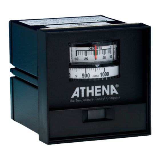
- Page 2 Introduction Congratulations on your purchase of an Athena® Series 2000 analog temperature controller. It is a U.L. listed, 1/4-DIN controller for use in a variety of applications. Standard features include time proportioning with auto-adjusting cycle time, adjustable bandwidth (for on-off to wide band proportioning), and offset (manual reset).
-
Page 3: Table Of Contents
Table of Contents Preliminary Instructions Mounting Output Configurations Power Wiring Circuits Thermocouple Wiring Circuits RTD Wiring Circuits Thermocouple Placement Operation Front Panel Layout Output Function Switches Adjustments Maintenance Specifications Ordering Codes Troubleshooting Warranty Unit Repairs 3/15/2020 DESCRIPTION REVISION DATE Model 2000 Operation Manual TITLE 900M507U01 DATE... -
Page 4: Mounting
Shielded sensor cables should always be terminated at one end only. If additional RFI attenuation is required, noise suppression devices such as an R.C. snubber at the external noise source may be used. If you wish, you may order this suppressor directly from Athena, part number 235Z005U01. - Page 5 Wiring Typical Wiring Diagrams for -T & -B Outputs B-Type - 840 W maximum. 120 Vac heater. (Non-inductive loads only) For larger loads, replace heater connections with contactor, as required. Maximum inductive load rating is 3 A at 120 V and 1.5 A at 240 V. The N.C. con- tacts can be used for cooling.
-
Page 6: Thermocouple Wiring Circuits
Wiring -F, -S Output - 120/240 Vac The -F output is 20 mA at the low temperature end of the proportional band and 4 mA at the upper end of the proportional band. Maximum load resistance is 1000 ohms. The -S output is a time-proportioned 20 Vdc signal. These controllers cannot be used with a device that does not have an isolated input. -
Page 7: Thermocouple Placement
Thermocouple Placement Proper thermocouple placement can eliminate many problems in the system. The probe should be placed so that it can detect any temperature change with little thermal lag. In a process that requires fairly constant heat output, the probe should be placed close to the heater. In processes where the heat demand is variable, the probe should be close to the work area. -
Page 8: Front Panel Layout
Layout of the front panel is shown below. To reach the adjustments, swing the top of the door forward and down. The proportional band adjustment is on the right side and sets the gain of the controller. The offset Front Panel (manual reset) adjustment is on the left and corrects for offsets from the setpoint temperature. -
Page 9: Adjustments
Configuring Output Function There is a switch assembly on the bottom board (see bottom board illustration). This four-position switch regulates cycle time and output selection. It is factory-configured for the plug- in output ordered. Check the Switches output function chart to make sure the configuration is correct for your application. Switches 1&2: These switches act together to select either proportional current output or one of the time proportioning cycle times. -
Page 10: Maintenance
How to Set Reset, Proportional Band, and Rate Optional 3 Mode Auto reset action automatically, but slowly, corrects droop error in proportionally controlled processes. Ideal (PID) reset time is one half the period of oscillation of the process. Slower settings are safe, but sluggish. Faster settings will cause continuous oscillation. -
Page 11: Specifications
Specifications Line Voltage 120/240 V ± 10% to ± 15%, 50-60 Hz Power Consumption Less than 5 VA Analog-Single turn potentiometer 270° rotation Setpoint 0.2% span Setpoint Resolution Temperature: Deviation meter ±50°F or ±30°C of setpoint Indication Load: Red LED output light Alarm: Red LED ±0.5% of span at calibration points Accuracy... -
Page 12: Troubleshooting
Before you call, please look at this section to see if your question is covered here. If you do call for technical assistance, be ready to supply the following information: • complete model number of controller Troubleshooting • symptoms of the problem •... - Page 13 Symptom. Temperature overshoots, or Check - Check bandwidth oscillates Loose heater or sensor fit. Poor relative location. Probable Cause. Corrective Action Process overpowered - Reduce total heater power Bandwidth too narrow - Widen band Process or sensor lag - Improve fit, locate closer together Symptom.
-
Page 14: Warranty
Proprietary information of Athena Controls, Inc. is furnished for customer use only. No other use is authorized without the written permission of Athena Controls, Inc. -
Page 16: Model 2000 Operation Manual
Athena Controls, Inc. Plymouth Meeting, PA +1 (610) 828 2490 AthenaControls.com sales@athenacontrols.com 3/15/2020 DESCRIPTION REVISION DATE Model 2000 Operation Manual TITLE 900M507U01 DATE SCALE CHECKED DRAWN...


Need help?
Do you have a question about the 2000 Series and is the answer not in the manual?
Questions and answers