Table of Contents
Advertisement
Quick Links
Advertisement
Table of Contents

Related Manuals for Athena 18C Series


Summary of Contents for Athena 18C Series
- Page 1 18C, 19C SERIES TEMPERATURE/PROCESS CONTROLLER OPERATION MANUAL...
- Page 2 INTRODUCTION Congratulations on your purchase of an Athena Series C Temperature/Process Controller. It is designed for ease of use and reliability wherever accurate control is required. After following the instructions for installation, simply step through and set your operating parameters using the controller’s easy menu system.
-
Page 3: Table Of Contents
TABLE OF CONTENTS Installation Dimensions and Mounting Wiring Wiring for Options Output Types Operation Front Panel Controls Power On Security Levels Operating Modes Menu System Overview Parameter/Menu Descriptions Input Menu Temperature Input Process (Linear) Input Display Menu Output Menu Control Menu PID Output and Control Menus On/Off Output and Control Menus Alarm Menu... -
Page 4: Installation
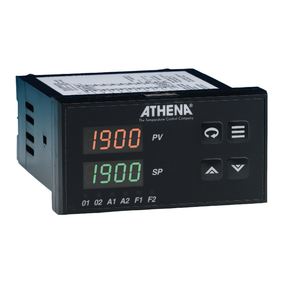
INSTALLATION Measurements between centerlines of panel cutouts are the minimum recommended. Unpacking and Inspection 1. Inspect shipping carton for obvious signs of mishandling. 2. After removing the controller from the shipping carton, inspect it carefully for damage. Never attempt to install and use a damaged unit. - Page 5 DIMENSIONS MODEL 1 800 1 800 MODEL 1 900 1 900 01 02 A1 A2 F1 F2 4.654" 3.950" (1 18.21 mm) (1 00.33 mm) 3.937" MODEL 25C 0.717" (1 00 mm) (8.21 mm) 3.950" 3.600" (1 00.33 mm) (91 .44 mm) XT25 Figure 2.
-
Page 6: Wiring
If additional RFI attenuation is required, noise suppression devices such as an R.C. snubber at the external noise source may be used. If you wish, you may order this suppressor directly from Athena, part number 235Z005U01. Figure 4. Contact Identification Thermocouple circuit resistance should not exceed 100 ohms for rated accuracy;... -
Page 7: Wiring For Options
WIRING Voltage Inputs: Connect the positive voltage input to contact #20; the negative input to contact #19. Current Inputs: Connect the positive current input to contact #20; the negative input to contact #19. Figure 7. Process and Linear Input Wiring The Series C power supply accepts 100 to 250 Vac and 100 to 250 Vdc line power without any switch settings or polarity considerations. - Page 8 DUAL 24 VDC OPTION #S: DUAL 24 VDC ALARM OUTPUTS ALARM OUTPUTS Figure 12. Wiring for Dual 24V dc Alarm Outputs Option Description: Dual 24 V outputs with clamping diodes Source current is limited to 25 mA (1000 ohm resistor) Open circuit voltage is 25 volts Isolation: Isolation 300 volts ac/dc either output to instrument...
- Page 9 RS-232 OPTION #A: RS-232 (ONE-TO-ONE) COMMUNICATIONS COMMUNICATIONS Figure 14. Wiring for RS-232 Communications Option Description: Provides a one-to-one connection between the controller and an RS-232 port. Computers, PLCs, or dumb terminals may be used to set and access controller data. RS-485 OPTION #B &...
- Page 10 OPTIONS #1, #2, #3, #4: TRANSDUCER EXCITATION TRANSDUCER EXCITATION Figure 16. Wiring for Transducer Excitation Option Description: The transducer excitation option provides power to remote transducers. The transducer outputs, in turn, provide a signal to the controller input which can be scaled in the appropriate engineering units. Option 1: 10 Vdc Option 2: 12 Vdc Option 3: 15 Vdc...
- Page 11 REMOTE ANALOG OPTION SA, SB, SC, SD, SE, and SF: REMOTE ANALOG SETPOINT SETPOINT OPTIONS SA, SB, SC, SD, SF OPTION SE 0-5 V/1-5 V/0-10 V 0-20 mA/4-20 mA Enable Enable Switch Switch Remote analog setpoint Switch input only Remote analog setpoint (potentiometer with enable (voltage/current input) switch)
-
Page 12: Output Types
OUTPUT TYPES The Type “B” output is a mechanical device and subject to wear. To extend the life of the relay, set the Cycle Time for the relay output to the longest duration that still affords good control. When you ordered your Series C controller specific output types were specified, designated as “B”, “E”, “F”, “G”, “S”, “T”... -
Page 13: Operation
OPERATION Note: The image shows a 25C, but the Output 1 operation, function and sequence of the LED indication buttons is the same for the model 18C of Heat cycle and 19C. (Output 1 action) Output 2 LED indication of Cool cycle (Output 2 action) Alarm 1 LED indication... - Page 14 The Athena Series C controllers are versatile instruments that are capable of using many types of input CONFIGURATION values and implementing several types of control strategies. To support this versatility, the Series C SEQUENCE controllers are capable of storing values for many confi guration parameters. Interrelationships exist between the parameters.
- Page 15 The following table summarizes the confi guration and startup tasks to be accomplished once the controllers are mounted and wired as described in this manual. The confi guration sequence does matter, because there are interdependencies among parameters. We recommend confi guring the controllers in the sequence shown below.
-
Page 16: Security Levels
SECURITY LEVELS The security level feature allows you to limit access to the menus, setpoint, and operating mode selection according to the needs of your application. The security levels provided are Key Lockout, Setpoint, Setpoint plus Mode, User, Configuration, and Factory. The controller’s To view or change security level from the Process Variable display, press and hold the Menu Access initial security level,... -
Page 17: Menu System Overview
OPERATING MODES Display Description Manual (Fixed Output Percentage). Used to set control output percentage independent of Process Value. Manual operating mode overrides To set percentage, use the Menu Access key to select and then use the Raise automatic control, or Lower keys to set the value. -
Page 18: Input Menu 1
As stated above, to access the Menus, press and hold the Menu Access key for approximately 3 seconds until a menu label appears in the upper display. There are additional menus presented when an MENU SYSTEM option is selected under the Option menu; however, the options are non-functional unless the appropriate OVERVIEW option board has been installed. - Page 19 PARAMETER OPTIONS WITHIN INDIVIDUAL MENUS INPUT MENU We recommend initial set up starts at the Input menu where the first parameter that needs to be set is Input Type. The remaining Input Menu parameters will change, depending upon whether a linear input type or a temperature input type is selected.
- Page 20 EMPERATURE INPUT TYPE HAS BEEN SELECTED THE FOLLOWING OPTIONS WILL SUBSEQUENTLY APPEAR IF THE BUTTON IS SELECTED Display Parameter Available Selections Bias (Display off set) - Use the to set the bias value. Bias allows the operator to compensate for any difference between sensor temperature and the point to be measured.
- Page 21 INEAR NPUT YPE HAS BEEN SELECTED THE FOLLOWING OPTIONS WILL SUBSEQUENTLY APPEAR IF THE BUTTON IS SELECTED Display Parameter Available Selections to set the bias value. Bias Bias (Display off set) - Use the allows the operator to compensate for any difference between sensor temperature and the point to be measured.
- Page 22 DISPLAY MENU How Do I Get Here? 1. Press for 3 seconds until menus appear. 2. Press until appears. 3. Press until appears. The SV display will alternate between the parameter and its value. 4. Press to make selection Display Parameter Available Selections...
-
Page 23: Output Menu
The first parameter that needs to be set in the Output Menu is the Output Type. There are four possible Output Type configurations: PID, On/Off, Alarm, or Off; the remaining menu parameters in the Output Menu OUTPUT MENU will change, depending on the Output Type selected. The Control Menu will also change depending on the Output Type selected. -
Page 24: Control Menu
The C Series controllers support both PID and on/off control. If the controller is equipped with two standard outputs, the outputs can be configured for two different types of control. The CONTROL MENU parameters used to customize the control operation are in the (control) menu which is avail- ... -
Page 25: Pid Output And Control Menus
PARAMETER OPTIONS FOR PID CONTROL IN OUTPUT AND CONTROL MENUS OUTPUT MENU Display Parameter Available Selections Output 1 Action - Reverse acting (heating) How Do I Get Here? - Direct acting (cooling). 1. Press for 3 seconds until menus to set the cycle time between 1 Output 1 Cycle Time * - Use the... - Page 26 PARAMETER OPTIONS FOR ON/OFF CONTROL IN OUTPUT AND CONTROL MENUS OUTPUT MENU How Do I Get Here? Display Parameter Available Selections 1. Press for 3 Output 1 Action - Reverse acting (heating) seconds until menus appear. - Direct acting (cooling). ...
- Page 27 The first step in configuring an alarm is to choose the alarm action. The choices are: NOTES ON • (off) – The alarm will not be used. ALARMS • (normal) – The LED will be lit (and the optional alarm output activated) when the process value ...
-
Page 28: Alarm Menu
ALARM MENU Control Menu does not apply to an Alarm Output Type; therefore, the Control Menu does not appear. Alarms A1 & A2 can be set up using this same information in the menu. How Do I Get Here? 1. Press for 3 seconds until menus appear. - Page 29 “Ramping” protects a process from rapid changes in the setpoint and the resulting thermal shock, as the NOTES ON controller tries to force the process variable to follow. Athena temperature controllers have the facility to ramp their eff ective setpoint towards the fi nal target value at a predefi ned rate. A deviation alarm is often RECIPE (RAMP/ used with this feature to ensure the process closely follows the rate ramp.
- Page 30 Multi-Step Ramp This selection will enable the programming of a recipe (make all ramp/soak recipe variables visible). Recipes can be resumed on startup if interrupted by a power failure or initiated, held, and terminated from the front panel via the Mode Menu or with the logic input option (initiate and held/resumed only). The recipe cannot be edited while running Holdback Band...
- Page 31 The following seven parameters shown in the table below are only available when Multi-Step Ramp is selected. Display Parameter Available Selections Recycle Number - Single Setpoint Ramp Power Fail Resume - Off - On. Ramp Times 1-8 Use the to select the ramp time, between 1 ...
-
Page 32: Supervisor Menu
You can use the supervisor menu to specify the output percentages to be used if the controller detects a SUPERVISOR problem with the process input (failsafe values), and the length of the time period during which the input MENU should change in response to output action if the input and output are working normally (loop break time). You can also use this menu to see the highest and lowest process value received by the controller since the controller was powered up. -
Page 33: Calibration Menu 3
The calibration menu does not contain confi guration parameters, instead it is used to display the values for CALIBRATION which a simulated input should be applied to the controller input terminals during calibration of the zero off set MENU and the span adjustment. It is also used to initiate the calibration operation after the controller has been prepared. -
Page 34: Options Menu 3
The C Series can support a variety of options, including serial communications. Use of most of these options requires that you confi gure a few parameters.which are arranged in menus, one for each option. The OPTIONS MENU available options include: REMOTE SETPOINT - this option allows you to select either of two setpoints for your process. -
Page 35: Communications Menu
OPTION #30: RS-232 (ONE-TO-ONE) COMMUNICATIONS AND OPTION #31: RS-485 (ONE-TO-MANY) COMMUNICATIONS COMMUNICATIONS MENU How Do I Get Here? Please note that this menu can only be seen / used when the controller has been set to the highest security setting - Factory ( ) . -
Page 36: Contact/Digital Input Menu
CONTACT/DIGITAL OPTIONS #40, #41, #42: CONTACT/DIGITAL INPUT WITH ALARM INPUT MENU Please note that this menu can only be seen / used when the controller has been set to the How Do I Get Here? highest security setting - Factory ( ) . - Page 37 AUXILLIARY OPTIONS #PA, #PB, #PC, #PD: AUXILIARY OUTPUT OUTPUT MENU Please note that this menu can only be seen / used when the controller has been set to the highest security setting - Factory ( ) . We strongly recommend that under normal operations, ...
- Page 38 REMOTE ANALOG OPTIONS #SA, #SB, #SC, #SD, #SE AND #SF REMOTE ANALOG SETPOINT SETPOINT MENU Please note that this menu can only be seen / used when the controller has been set to the highest security setting - Factory ( ) .
-
Page 39: Autotune Damping
4) DERIVATIVE, also known as rate, senses the rate of rise or fall of system temperature and automatically adjusts the proportional band to minimize overshoot or undershoot. Athena’s PID (three mode) controllers are capable of exceptional control stability when properly tuned and used, allowing operators to achieve the fastest response time with the smallest overshoot. The information for tuning this three mode controller may be different from other controller tuning procedures. - Page 40 TO PLACE THE CONTROLLER IN AUTOTUNE MODE: How Do I Get Here? 1) We assume that you have configured the controller according to the different menus at this point. 1. From the 2) If the controller is not already in Standby mode, place it in Standby now as follows. Press and hold the mode, use the Mode/Enter key for three seconds and the display will indicate your current operating mode.
-
Page 41: Manual Tuning 4
MANUAL TUNING PROCEDURE (ZEIGLER-NICHOLS PID METHOD) MANUAL TUNING This tuning method may be used for non-temperature control processes or if the spread between ambient temperature and process operating temperature is small. While some processes other than heat or cool applications may respond successfully to autotuning procedures, the controller may need to be manually tuned for non-temperature processes. -
Page 42: Operation In Manual Mode
MANUAL OPERATION OPERATION IN MANUAL MODE In the rare occasions where you want to use the controller in ‘manual’ mode, you must change the operating mode to Fixed Output Percentage, . To do this press the mode key, , for 4 seconds until the control mode is displayed, Use the raise or lower keys to select FOP as the operating mode;... -
Page 43: Error Codes 4
ERROR CODES Display Indicated Problem Corrective Action Open sensor Inspect and correct for a bad sensor; inspect and correct wiring continuity between sensor and controller. Reversed Sensor Inspect and correct the polarity of the sensor. Additionally, check the selection of the sensor type in the Input menu If an error code cannot Loop Break... - Page 44 OPERATING LIMITS TECHNICAL Ambient Temperature 32°F to 140°F (0°C to 60°C) SPECIFICATIONS Relative Humidity Tolerance 90%, Non-Condensing Power 80 to 265 V, 50/60 Hz (Single-Phase); 120 to 375 Vdc; 24 Vac/dc (optional) Power Consumption Less than 6 VA PERFORMANCE Accuracy ±0.20% of Full Scale, (±0.10% Typical), ±1 Digit Setpoint Resolution 1 Count / 0.1 Count...
- Page 45 Solid state relay, normally closed, 24 - 240 Vac COMMUNICATIONS RS-232 with Athena+ Protocol (Option id A) RS-485 with Athena + protocol (Option id B) RS-485 with MODBUS protocol (Option id E) REMOTE ANALOG SETPOINT 0 to 5V dc with switch (Option id SA)
-
Page 46: Recalibration Procedures 4
RECALIBRATION PROCEDURES The Series C controller is precalibrated at the factory. Under normal circumstances, the factory calibration should be valid for the life of the instrument. If recalibration should be required, allow the controller to warm up for 15 minutes and follow these steps carefully. How Do I Get Here? 1. -
Page 47: Glossary 4
ALARM DELAY - the time delay between the detection of the alarm condition and the initiation and indication of the output action. GLOSSARY ALARM INHIBIT - prevents low setpoint alarm activation during cold startup applications. AUTOTUNING - “Autotuning” or “self-tuning” simplifies process control by determining the tuning parameters based on an automated analysis of the controlled process’s behavior. - Page 48 LOWEST READING - records the lowest process value read by the controller. May be reset to zero by using the Raise or Lower arrow keys. LOWER SETPOINT LIMIT - prohibits users from adjusting the setpoint lower than the selected value. MANUAL RESET - an adjustment that moves the Proportional Band up or down by a fixed percentage so that more or less power is applied at setpoint.
-
Page 49: Faqs
Before you call, please look at this section to see if your question is covered here. If you do call for technical FAQS assistance, be ready to supply the following information: • complete model number of controller • symptoms of the problem •... - Page 50 The last digit of the PV display changes very frequently. How can I slow it down? If the display is confi gured to show one or more decimal places, those values might change frequently, sometimes so quickly that the value is hard to read. Go to the (display) menu and increase the value ...
- Page 51 NFORMATION IN A LACE Configured Parameters Reference Data Model Number ______________________________ Serial Number _______________________________ Zone Location _______________________________ Firmware Version No. _________________________ (Displayed when the controller is powered up after all the segments on both lines of the display have been tested.) Please keep this information handy –...
-
Page 52: Warranty/Repairs 5
Proprietary information of Athena Controls, Inc. is furnished for customer use only. No other use is authorized without the written permission of Athena Controls, Inc. - Page 54 Athena Controls, Inc. Plymouth Meeting, PA +1 (610) 828 2490 AthenaControls.com sales@athenacontrols.com 1/22/2020 DESCRIPTION REVISION DATE Model 18C, 19C, 25C Operation Manual TITLE 900M505U01 DATE SCALE CHECKED DRAWN...
Need help?
Do you have a question about the 18C Series and is the answer not in the manual?
Questions and answers