
Subscribe to Our Youtube Channel
Related Manuals for Athena 16C series


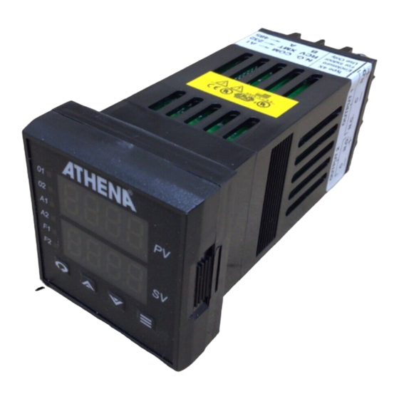
Summary of Contents for Athena 16C series
- Page 1 SERIES TEMPERATURE/PROCESS CONTROLLER Standard Options and Digital Communications User’s Guide...
- Page 2 © Copyright 2004, Athena Controls, Inc.
-
Page 3: Table Of Contents
Auxiliary Output (Options #60, #61, #62, #63) Remote Analog Setpoint (Options #80, #81, #82, #83, #84) Guide to Digital Communications Remote Communications Options Athena+ Protocol - Message Format - Sample Commands - Request Messages - Response Messages - Communications Parameter List... -
Page 4: Dual Alarm Outputs (Options #10 And #22)
Dual Alarm Outputs Option #10: Dual Alarm Output, N.O. Option #22: Dual Alarm Output, N.C. This optional hardware module provides two alarm drive outputs. LED indicators A1 and A2 are used to indicate alarm conditions as configured in the Alarm Menu. Option Description: Option 10: Dual alarm, N.O. -
Page 5: Dual Open Collector Alarms (Option #20)
Dual Open Collector Alarms Option #20: Dual Open Collectors, NPN, Isolated with Clamping Diode Option Description: Dual open collectors, NPN, isolated, with clamping diode Recommended operating conditions: Supply Voltage Pins 13 & 14; 200 working Vdc max. (Never exceed 300 Vdc) Collector Current 50 mA max. - Page 6 Dual 24 Vdc Alarm Outputs Option #21: Dual 24 Vdc Alarm Outputs Option Description: Dual 24 V outputs with clamping diodes Pins 13 & 7 are connected internally Source current is limited to 25 mA (1000 ohm resistor) Open circuit voltage is 25 volts Isolation: Isolation 300 volts ac/dc either output to instrument...
-
Page 7: Relay, N.o. Alarm Output (Option #23)
Relay, N.O. Alarm Output Option #23: Relay, N.O. Alarm Output Option Description: NO (Normally open) relay contact is closed when either alarm is active. Jumpers on the board can be removed to activate the output for a single alarm only: JP1 - Alarm A1 JP2 - Alarm A2 The relay life is greater than 100,000 operations at 5 operations per second switch-... - Page 8 RS-232 Communications Option #30: RS-232 (one-to-one) Communications Option Description: Provides a one-to-one connection between the controller and an RS-232 port. Computers, PLCs, or dumb terminals may be used to set and access controller data.
-
Page 9: Rs-485 Communications (Option #31)
RS-485 Communications Option #31: RS-485 (one-to-many) Communications Option Description: Provides one-to-many communications. If run exceeds 1000 ft., terminate the controller furthest from the computer by connect- ing a 120-ohm, 1/4-watt resistor between terminals 13 and 14. Converter is supplied with a wallplug-mount power transformer. -
Page 10: Contact/Digital Input With Alarm
Contact/Digital Contact/Digital Input with Alarm Input with Alarm Options #40, #41, #42: Contact/Digital Input with Alarm Input Option Menu Option Description: Dual function board (functions unrelated) a. Output alarm is energized when either A1 or A2 is active. b. Digital input controls Remote Standby, Ramp-Soak Run/Hold, OR Second Setpoint Select. -
Page 11: Transducer Excitation
Transducer Excitation Option #50, #51, #52, #53: Transducer Excitation Option Description: The transducer excitation option provides power to remote transducers. The transducer outputs, in turn, pro- vide a signal to the controller input which can be scaled in the appropriate engineering units. Option 50: 10 Vdc Option 51: 12 Vdc Option 52: 15 Vdc... -
Page 12: Auxiliary Output (Options #60, #61, #62, #63)
Auxiliary Output Auxiliary Output Option #60, #61, #62, #63: Auxiliary Output Option #60, #61, #62, #63: Auxiliary Output Input Option Menu Option Description: The Setpoint Variable or Process Variable is transmitted to a remote device (chart recorders, indica- tors, data recorders, computers, process controllers, etc.) with 1 of 4 different interfaces: Option 60: 4-20 mA Option 61: 1-5 V... -
Page 13: Remote Analog Setpoint
Remote Analog Setpoint Option #80, #81, #82, #83, #84: Remote Analog Setpoint Option Description: Remote setpoints use either voltage or current inputs, depending on the specified option: Option 80: 0-5 V Option 81: 1-5 V Option 82: 0-20 mA Option 83: 4-20 mA Option 84: 0-10 V The input signal is scalable in the Remote Analog Setpoint Menu. - Page 14 Series with Digital Communications Option...
-
Page 15: Remote Communications Options
Digital Communications Option Remote Communications Options RS-232 Three remote commu- nications options are This method allows bidirectional data transfer via a three- available for the 16C conductor cable consisting of signal ground, receive input and which allow interfacing to remote devices transmit output. - Page 16 Digital Communications Option This method allows bidirectional data transfer over a twisted pair cable. The twisted pair cable is a transmission line; therefore, terminating resistors are required at the most distant ends of the line to minimize reflections (typically 120 ohms at each end). The RS485 circuit is fully optically isolated, eliminating ground loop problems.
-
Page 17: Athena+ Protocol
Athena+ Protocol Digital The Athena+ Protocol provides an easy way to query and Communications modify controller parameters using a personal computer and the Option optional digital communications option of the 16C. In this manual, the word “host” refers to the personal computer that’s communicating with the controllers in the serial link, and the... -
Page 18: Message Format
Digital Communications Option Message Formats All Athena+ messages adhere to the general format of: [START CHAR][ID][ZONE][TYPE][PARAM][ERROR] [DATA][CHKSUM][END CHAR] START CHAR This is a single character which designates the start of the mes- sage. For a Request message, this character is the ASCII ‘$’ and for a Response message, this character is the ASCII ‘%’. - Page 19 Digital Communications Option same values as their decimal counterparts and the letters A-Z have the values of 100 - 350 inclu- sively in increments of 10. Example: Message Code Value Decimal Value 0 + 0 = 00 90 + 9 = 99 100 + 0 = 100 100 + 2 = 102 110 + 8 = 118...
- Page 20 Digital Communications Option Type This is a single character identifying the type of message. The fol- lowing table lists the type characters for all messages. TYPE character Message Type Read Request or Read Response Returning a Positive Result Read Response Returning a Negative Result Write Positive Value Request and Response...
- Page 21 Digital Communications Option PARAM This is a two character, message specific, parameter ID. For a Read/Write Request or Response message, this ID identifies the controller parameter. For an Auxiliary Command Request or Response message, this ID specifies the command. STATUS This is a single-character field used in all response messages, con- taining a status code specifying the status of the request message received.
- Page 22 Digital Communications Option IMPORTANT: The data field in the Read and Write Request and Response messages must and will only contain the characters ‘0’-’9’, and the decimal point ‘.’. All other characters are considered illegal. When the data field is listed as Unused or Ignored in an auxiliary command, it does not mean that the field can be skipped when sending in the request message.
- Page 23 Digital Communications Option Examples of valid numeric representations for a 6 character data field: Numeric Value ASCII Representation 3.0000 000003 003.00 100.00 0100.0 000100 003.20 0003.2 Examples of invalid numeric representations for 6 character data field: (B represents a blank, or a space, character) Numeric Value Bad ASCII Representation Why?
-
Page 24: Request Messages
Digital Communications Option CHKSUM This is a two character Message Code Numbering System, repre- senting the sum of all the ASCII values of all the characters (excluding the START, CHAR, the END CHAR, and the CHKSM themselves) in the message. The sum is computed using the fol- lowing formula: CHKSM = SUM(All Message Characters)%256 % represents the modulus operator. - Page 25 Digital Communications Option The Read Request: The Read Request is used to query parameter values and it has the following message format: [START CHAR][ID][ZONE][TYPE][PARAM][CHKSUM][END CHAR] Field Description: TYPE Must contain the uppercase letter ‘R’. Request Message Description $Ø1Ø1RØ5C1<CR> Queries the value of the Process Variable of Controller #1.
- Page 26 Digital Communications Option The Write Request: The Write Request is used to modify parameter values and it has the following message format: [START CHAR][ID][ZONE] [TYPE][PARAM][DATA][CHKSUM][END CHAR] Field Description: TYPE This field must contain one of the following two characters. W– Value in DATA is a positive value. w–...
-
Page 27: Response Messages
Response Messages are replies to the requests sent from the host. For each request received, the slave will reply back with a response. For all requests, the Athena+ Protocol specifies a maximum response time of 100 milliseconds. If a response is not received after 100 milliseconds, that request can be considered lost. - Page 28 Digital Communications Option The Read Response: The Read Response will be sent in response to a Read Request. Some examples: Request Message Description %Ø1Ø1RØ5Ø21.123K8<CR> The value of the Process Variable is 21.123 Degrees C. %Ø2Ø1R1Ø1G7<CR> A serial transmission has occurred: Framing Error %Ø1Ø1rØ9Ø21.ØØØN8<CR>...
- Page 29 Digital Communications Option The Write Response: The Write Response will be sent in response to a Write Request. Some examples: Request Message Description %Ø1Ø1WØ93I1<CR> A serial transmission error has occurred: Parity error. Write failed. %Ø1Ø1w1ØØK2<CR> RAM copy of setpoint #1 modified successfully.
-
Page 30: Communications Parameter List
Digital Communications Option Table 1. Communications Parameter List (Athena+ Protocol) Parameter Parameter Number Description Number Description Controller Type Manual Control Software Version 2 Percentage Communications 2Ø Output 1 Deadband Version Output 1 Hysteresis Status Byte Output 1 Proportional Process Value... - Page 31 Digital Communications Option Table 1. Continued Parameter Parameter Number Description Number Description Ramp Time 8 Soak Time 8 5Ø Ramp Event 1 Soak Event 1 Ramp Event 2 Soak Event 2 Ramp Event 3 Soak Event 3 Ramp Event 4 Soak Event 4 Ramp Event 5 Soak Event 5...
- Page 32 Digital Communications Option Table 1. Continued Parameter Parameter Number Description Number Description TC/RTD Decimal Position Output 1 Alarm Operation Linear Decimal Position Output 1 Alarm Delay Display Filter Output 1 Alarm Inhibit Display Units AØ Output 1 Process Display Blanking Alarm Setpoint Output 1 Deviation Alarm 1 Action...
- Page 33 Digital Communications Option Table 1. Continued Parameter Parameter Number Description Number Description Loop Break Time Contact/Digital Highest Reading Switch Function Lowest Reading Autotune State Option Selection N/A Recipe State TC Zero Calibration Current Recipe FØ TC Span Calibration Segment RTD Zero Calibration Active Setpoint RTD Span Calibration Resume Exhaustion...
-
Page 34: Auxiliary Commands
Digital Communications Option Auxiliary Commands: Command: Load Parameter Defaults Parameter #: Description Restore all menu parameters to their default values. Request Data Field: Ignored. Response Data Field: Ignored. Command: Perform Process Low Calibration Parameter #: Description: Performs a Low Calibration. The data field in the request message specifies the process. - Page 35 Digital Communications Option Request Data Fields: A 10 character ASCII representation of a numeric value specifying what to calibrate. 0 - Thermocouple 1 - RTD, Resistive Thermal Device 2 - Linear 3 - RAS, Remote Analog Setpoint Response Data Field: Ignored.
- Page 36 Digital Communications Option 0 - Thermocouple 1 - RTD, Resistive Thermal Device 2 - Linear 3 - RAS, Remote Analog Setpoint Command: Retrieve Display Parameter #: Description: Retrieves the string currently dis- played on the slave’s display. The data field in the request message specifies which display and the data field in the response message contains the string.
-
Page 37: Communications Error Codes
Digital Table 2. Communications Error Codes Returned. Communications Option Code Description No error. Framing error. Hardware error. Parity error. Bad character in the TYPE field. Bad message. Message cannot be understood. Bad checksum. The checksum received did not match the checksum of the message. Bad zone ID. - Page 38 Communications Option Menu Option “ED” – SPI Protocol...
- Page 39 NOTES...
- Page 40 For technical assistance, call toll free 1-800-782-6776 (in the U.S.) 610-828-2490 (from anywhere in the world), e-mail: techsupport@athenacontrols.com. Athena Controls, Inc. 5145 Campus Drive Plymouth Meeting, PA 19462 USA Toll-free: 800.782.6776 Tel: 610.828.2490 Fax: 610.828.7084 techsupport@athenacontrols.com athenacontrols.com 900M012U00 REV “C” - 05022005...
Need help?
Do you have a question about the 16C series and is the answer not in the manual?
Questions and answers