Table of Contents
Advertisement
Advertisement
Table of Contents

Related Manuals for Athena 2000 Series


Summary of Contents for Athena 2000 Series
- Page 1 SERIES 2000 / 3020 ANALOG TEMPERATURE CONTROLLERS Instruction Manual...
-
Page 3: Table Of Contents
If you have questions or require any assistance with your con- troller or with any temperature control problem, please contact your Athena representative or call technical support at 1-800- 782-6776. Outside the USA, please call 610-828-2490. Precautions After unpacking, inspect the instrument for any physical dam- age that may have occurred in shipping. -
Page 4: Output Configurations
Output Type “B” Relay with 7 A at 120 V and 5 A at 240 V Configurations contacts, on-off and time proportioning Type “F” Signal current, 4-20 mAdc Type “L” Relay with 7 A at 120 V and 5 A at 240 V contacts, on-off, reset switch Type “T”... -
Page 5: Power Wiring Circuits
Consult serial tag on the unit and select power wiring dia- Power Wiring gram for the model specified. All wires are connected to the Circuits terminals on the back of the case. Screw terminals are pro- vided. Make appropriate connections using proper size wire for rated controller load power circuits. - Page 6 Power Wiring Circuits Typical Wiring Diagrams Figure 2b: Typical 120 Vac for -B & -T Output -F, -S Output - 120/240 Vac The -F output is 20 mA at the low temperature end of the pro- portional band and 4 mA at the upper end of the proportional band.
-
Page 7: Thermocouple Wiring Circuits
Thermocouple Wiring Circuits Use thermocouple and extension wire that conforms to the appropriate thermocouple type specified on the serial number tag. In thermocouple circuits, the negative lead is colored red. Extension wires must be of sufficient size so that on long runs the thermocouple circuit resistance does not exceed 100 ohms. -
Page 8: Operation
The typical control system contains the sensor, controller (2000/3020) Operation and the process (load). The sensor produces a small signal propor- tional to the measured temperature of the process. This signal is amplified by the controller, where it is compared with setpoint tem- perature. -
Page 9: Front Panel Layout
Layout of the front panel is shown below. To reach the adjust- Front Panel Layout ments, swing the top of the door forward and down. The pro- portional band adjustment is on the right side and sets the gain of the controller. The offset (manual reset) adjustment is on the left and corrects for offsets from the setpoint tempera- ture. -
Page 10: Adjustments
Output Function How to Configure Output Function Switches Switches There is a switch assembly on the bottom board (see bottom board illustration). This four-position switch regulates cycle time and output selection. It is factory-configured for the plug- NOTE: in output ordered. Check the output function chart to make Reconfigured or sure the configuration is correct for your application. - Page 11 wise (- direction) for high temperature as indicated by the Adjustments deviation meter. NOTE: If close control cannot be obtained after carefully repeating the above procedures, check to see if the thermo- couple probe is in good contact with the heated process, and if the heaters are correctly sized for the application.
-
Page 12: Maintenance
until it finally stabilizes, the reset time is correct. Adjustments Then proceed to Step 7. If it continues to oscillate, reset it to short, continue with Step 6. NOTE: Each 6. Set reset switches to the next slowest time. process will tolerate Repeat Step 5. -
Page 13: Specifications
Specifications Supply Voltage: 120/240 Vac, +10% -15%, 50/60 Hz Setpoints: Series 2000 : Analog - single-turn potentiometer, 270° rotation Series 3020 : Mechanical digital potentiometer Setpoint Repeatability: +/-0.3% of span (Series 2000) Setpoint Resolution: Series 2000 : 0.2% of span Series 3020 : 1 °F or °C Input: Thermocouple Types J, K, T, R (Series 2000)Types J, K... -
Page 14: Ordering Codes
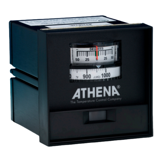
0 = None RTD (3-wire, 100 ohms) -200 to +600°F 80 to +120°F 0 to +300°F The deviation meter spans a Athena’s ZC/PC solid state 0 to +600°F range of 5° and reads in contactors, and Series 91 and 0 to +1000°F increments of 0.5°. -
Page 15: Troubleshooting
Troubleshooting Symptom Check Controller dead. No output Verify 120/240 Vac, 50/60 Hz input voltage. Check light, no meter deflection heater for shorts. Look for open breakers or open external fuse. Remove input power. Check continuity Probable Cause through power transformer primary. With ohmmeter, - No line voltage input read between pins: 8 and 9 for 225 or 450 ohms - Open PC board to back-... - Page 16 Troubleshooting Symptom Check Process control temperature dif- Check T/C lead wires at back of probe fers from setpoint when read Wire color indicates type of T/C with an external pyrometer. Verify type of wire Deviation meter nulls and process is stable. Probable Cause Corrective Action - T/C lead wires shorted close...
-
Page 17: Warranty
THIS EQUIPMENT IS WARRANTED TO BE FREE FROM DEFECTS OF MATERIAL AND WORKMANSHIP. IT IS SOLD SUBJECT TO OUR MUTUAL AGREEMENT THAT THE LIABILITY OF ATHENA CON- TROLS, INCORPORATED IS TO REPLACE OR REPAIR THIS EQUIP- MENT AT ITS FACTORY, PROVIDED THAT IT IS RETURNED WITH TRANSPORTATION PREPAID WITHIN TWO (2) YEARS OF ITS PUR- CHASE. -
Page 18: Unit Repairs
Features may be described herein which are not present in all hard- ware. Athena Controls assumes no obligation of notice to holders of this document with respect to changes subsequently made. Proprietary information of Athena Controls, Inc. is furnished for cus- tomer use only. - Page 20 For free technical assistance in the USA, call toll free 1-800-782-6776 or e-mail techsupport@athenacontrols.com Athena Controls, Inc. 5145 Campus Drive Plymouth Meeting, PA 19462 USA Tel: 610-828-2490 Fax: 610-828-7084 Toll-Free in USA: 1-800-782-6776 techsupport@athenacontrols.com athenacontrols.com 900M002U00 Revision B...
Need help?
Do you have a question about the 2000 Series and is the answer not in the manual?
Questions and answers