Audio Precision B Series Installation Instructions And Specifications
Audio analyzer
Hide thumbs
Also See for B Series:
- Installation instructions and specifications (58 pages) ,
- Installation instructions manual (92 pages) ,
- Installation instructions, specifications and project plans (65 pages)
Table of Contents
Advertisement
Advertisement
Table of Contents

Related Manuals for Audio Precision B Series


Summary of Contents for Audio Precision B Series
- Page 3 APx555 B Series audio analyzer Installation Instructions and Specifications B Series APx555 October, 2021...
- Page 4 DTS © Digital Surround is trademark of DTS, Inc. The Bluetooth® word mark and logos are registered trademarks owned by the Blue- tooth SIG, Inc. and any use of such marks by Audio Precision is under license. Other trademarks and trade names are those of their respective owners.
- Page 5 APx500 measurement software, and in the APx500 User’s Manual, included with the analyzer. The user’s manual is also available as a PDF on the APx500 Application Disc and on the Web at ap.com; additional copies can be ordered from Audio Precision or your local distributor.
-
Page 7: Table Of Contents
APx555 B Series audio analyzer analog I/O specifications ....... . . - Page 8 APx555 B Series Acoustic Audio Analyzer: Table of Contents...
-
Page 9: Safety
Do NOT substitute parts or make any modifications with- For continued fire hazard protection, fuses should be out the written approval of Audio Precision. Doing so may replaced ONLY with the exact value and type indicated on create safety hazards. Using this product in a manner not the rear panel of the instrument and discussed on page 20 of specified by Audio Precision can result in a safety hazard. - Page 10 Refer to the Audio Precision cautions against using their products in a accompanying Warning Label or Tag, and exercise extreme manner not specified by the manufacturer. To do otherwise caution.
-
Page 11: Sécurité
à la L’entretien devrait être effectué uniquement par un tech- page 24 de ce livret. nicien qualifié ou un distributeur Audio Precision agréé. La International Electrotechnical Commission (la Commis- Ne PAS dérouter le branchement de la mise à la terre de sion électrotechnique internationale) (CEI 1010-1) exige... - Page 12 Ne PAS remplacer de pièces ou effectuer de modifications uation potentiellement dangereuse, par exemple, la présence sans l’approbation écrite d’Audio Precision. Si c’est le cas, d’une tension dangereuse qui pourrait présenter un risque de il pourrait y avoir des risques pour la sécurité. Utiliser ce choc électrique.
- Page 13 être raccordées à un système protecteur de mise à la terre externe. Avis de non-responsabilité Audio Precision déconseille fortement l’utilisation de ses produits d’une manière non spécifiée par le fabricant. Une telle utilisation pourrait annuler toute garantie, endom- mager l’équipement ou présenter un risque de sécurité...
- Page 14 Sécurité APx555 B Series Audio Analyzer: Sécurité...
-
Page 15: Seguridad
28 de este folleto. cio deberá ser efectuado solamente por un técnico califi- International Electrotechnical Commission [La Comisión cado o un distribuidor autorizado de Audio Precision. Electrotécnica Internacional] (IEC 1010-1) requiere que los NO modifique la conexión de seguridad a tierra. Este terminales del circuito de medición que se utilizan sola-... - Page 16 NO reemplace partes ni haga modificaciones sin la aproba- ción por escrito de Audio Precision. Hacerlo podría causar riesgos de seguridad. El uso de este producto en una manera no especificada por Audio Precision puede resultar en un ¡ADVERTENCIA!—Este símbolo le alerta sobre una...
- Page 17 (aterrizada). Exención de responsabilidad Audio Precision advierte contra el uso de este producto de una manera no especificada por el fabricante. El hecho de no hacerlo de la manera indicada invalidaría las garantías, causaría daño al equipo, o representaría un riesgo de seguri-...
- Page 18 Seguridad APx555 B Series Audio Analyzer: Seguridad...
-
Page 19: Installation
If you are using APx500 software version 4.6 or later with PC system requirements an earlier APx analyzer (non “B Series”), you must attach The APx500 measurement software version 4.1 and later an authenticated APx KeyBox to the Software Options con- can be very demanding of the personal computer (PC) run- nector on the analyzer rear panel. - Page 20 Running the software with instrument hardware the PC system when used in high bandwidth testing. attached NOTE: You must have standard user rights or administrator rights to operate APx500 software. Guest users are not supported. APx555 B Series Audio Analyzer: Installation...
- Page 21 USB and will open the Hardware Update Wizard to search for the correct software driver. Select “Install the software automatically.” Win- dows will find the Audio Precision driver software installed with APx500 and connect to the instrument. APx555 B Series Audio Analyzer: Installation...
- Page 22 Carefully reinsert the fuse carrier module into the power entry module, and press it firmly into place. Connect the power cord from a mains power outlet to the power cord connector on the instrument rear panel. APx555 B Series Audio Analyzer: Installation...
-
Page 23: Installation (Fr)
Ces analyseurs portent la désigna- Veuillez noter que sans l’installation d’un dispositif APx tion « B Series » et suivent la nomenclature « B Series ». KeyBox correctement authentifié, le logiciel APx500 ver- Les analyseurs APx « B Series » n’exigent pas de dispositif sion 4.6 ou plus récente ne fonctionnera qu’en mode de... - Page 24 Demandes de mesures élevées Les demandes de mesures élevées (bandes passantes de mesure de plus de 90 kHz, nombre de canaux de plus de 2) fonctionneront beaucoup mieux avec un PC de puissance APx555 B Series Audio Analyzer: Installation (Fr)
- Page 25 APx500 comme décrit plus Sélectionner « Install the software automatically » (installa- haut. Brancher l’instrument avant d’installer le logiciel peut tion automatique du logiciel). Windows trouvera le logiciel APx555 B Series Audio Analyzer: Installation (Fr)
- Page 26 Installation (Fr) pilote Audio Precision installé avec APx500 et branché à Pour retirer le module porte-fusibles secteurs, consultez les l’instrument. figures ci-dessous et procédez comme suit : Lancez APx500 en cliquant deux fois sur le raccourci. Une fois l’instrument branché, on pourrait vous demander de mettre à...
-
Page 27: Instalación (Sp)
Software El APx KeyBox debe ser programado con el número de serie de su analizador en la fábrica de Audio Precision, y no Todos los sistemas APx utilizan el mismo software lau- puede ser usado con ningún otro Analizador APx. Puede reado, APx500. - Page 28 90 kHz, conteos de canal de más de 2) tendrán mejor rendimiento con una mejor PC; en algunos casos, las demandas de medición muy altas pueden ralen- tizar o detener las mediciones. APx555 B Series Audio Analyzer: Instalación (Sp)
- Page 29 Disco de Aplicación del APx500 y en línea en ap.com. otros cables USB con mal funcionamiento. Nota: Algunas PC tienen puertos USB opciona- les al frente de la PC, o en soportes de exten- APx555 B Series Audio Analyzer: Instalación (Sp)
- Page 30 El módulo del portador de fusible de fuente de alimentación es parte del módulo de entrada de energía, a la derecha del conector del dable de alimentación. APx555 B Series Audio Analyzer: Instalación (Sp)
-
Page 31: Abbreviations, Terms And Symbols
Abbreviations, Terms and Symbols used in the following specifications ADC or A/D ..Analog to Digital converter or conversion. BW ....Bandwidth or Measurement Bandwidth, nominally at –3 dB; a single number indicates only the upper limit. - Page 32 Abbreviations, Terms and Symbols...
-
Page 33: Apx555 B Series Audio Analyzer Analog I/O Specifications
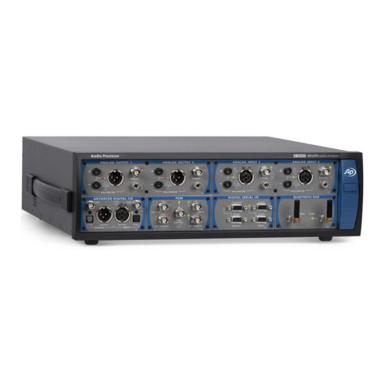
March 2020 NP0020.00030 rev 001 This illustration shows an APx555 in its standard configuration, with an ADIO module installed. These specifications cover the analog input and output functions of the Audio Precision B Series APx555. Specifications for the ADIO interface and other available interface modules including DSIO, HDMI, PDM, Bluetooth and AMC, are found in other sections of this document, as are Gen- eral and Environmental specifications for the entire APx555 B Series family. - Page 34 0-10.61 Vrms [30.0 Vpp] unbal & CMT Amplitude Setting Resolution Typically <0.001 dB or 0.05 µVrms Amplitude Accuracy, 1 kHz ±0.030 dB [±0.35%] +15°C to +30°C ±0.040 dB [±0.46%] 0°C to +45°C APx555 B Series Audio Analyzer: Analog I/O Specifications...
- Page 35 24-bit Σ-Δ DACs, SR = 192 kS/s. Frequency Range (Fs) 0.001 Hz to 80.1 kHz Setting resolution is typically 45 μHz [192 kHz / 2 ] over full range ±0.0003% [3 ppm] Lockable to external reference Frequency Accuracy APx555 B Series Audio Analyzer: Analog I/O Specifications...
- Page 36 0–37.7 Vpp unbal Amplitude Accuracy (1 kHz) ±0.05 dB [0.58%] Low/High Ratio Range 0 to –80 dB, and zero Ratio Accuracy (1 kHz) ±0.15 dB, 0 to –60 dB Unspecified below –60 dB. APx555 B Series Audio Analyzer: Analog I/O Specifications...
- Page 37 100 kHz 1-pole filter (tr ≈3.5 μsec); 2.96 kHz + 8 kHz [DIM-B8] other DIM square waves BW limited by 30 kHz 1-pole filter (tr ≈11.7 μsec) ±0.0003% [3 ppm] Frequency Accuracy APx555 B Series Audio Analyzer: Analog I/O Specifications...
- Page 38 Maximum File Size 32 MSamples 0 to 60.0 Vpp, bal; “.Wav” file must peak at digital full scale Amplitude Range 0 to 30.0 Vpp, unbal for calibrated amplitude. APx555 B Series Audio Analyzer: Analog I/O Specifications...
- Page 39 –0.400 V to +4.200 V in 1 mV steps May be additionally limited by the Posi- tive and Negative Peak limits if Pin Volt- age Protection is ON DC Bias Accuracy ±(0.3% + 3 mV) APx555 B Series Audio Analyzer: Analog I/O Specifications...
- Page 40 Typically <5 μV Typically >80 mA peak, 50 mA dc Maximum Output Current Up to 1A or 30 W, whichever is less. Peak Reverse Overload Outputs automatically disconnect if a damaging potential is sensed APx555 B Series Audio Analyzer: Analog I/O Specifications...
- Page 41 Level (Amplitude) Measurement Range < 1 µV to 300 Vrms, bal; < 1 µV to 160 Vrms, unbal Accuracy (1 kHz) +15°C to +30°C ±0.03 dB [±0.35%] 0°C to +45°C ±0.05 dB [±0.58%] APx555 B Series Audio Analyzer: Analog I/O Specifications...
- Page 42 HPSA OFF. Accuracy Harmonics to 100 kHz ±0.3 dB Harmonics to 300 kHz ±0.5 dB Harmonics to 1 MHz Typically +0.5 to –1.0 dB APx555 B Series Audio Analyzer: Analog I/O Specifications...
- Page 43 AC (< 10 Hz) AC coupling Butterworth (–3 dB) = 10 Hz to 1 MHz, 4-pole Elliptic (–0.01 dB) = 10 Hz to 1 MHz; 5-pole; 0.01 dB pass band ripple; ≤–60 dB stop band APx555 B Series Audio Analyzer: Analog I/O Specifications...
- Page 44 250 Hz–60 kHz and a dif- = (F1 + F2) / 2. mean ference frequency of 80 Hz–2.0 kHz [see note 7} ) must be ≥6 mean diff DIM-100, DIM-30, DIM-B, or DIM-B8 APx555 B Series Audio Analyzer: Analog I/O Specifications...
- Page 45 –90 to +270, ±180, or 0 to 360 deg Accuracy 5 Hz to 5 kHz ±0.15 deg 5 kHz to 20 kHz ±0.6 deg 20 kHz to 50 kHz ±1.5 deg Minimum Input 3 mV APx555 B Series Audio Analyzer: Analog I/O Specifications...
- Page 46 Low pass cutoff must be higher than high pass cutoff. DSP warping may significantly increase roll-off rate and lower ENBW. For THD+N and THD specifications, HPSA must be activated. Performance degraded if not using HPSA. APx555 B Series Audio Analyzer: Analog I/O Specifications...
-
Page 47: Adio Advanced Digital Input/Output Module Specifications
NP0020.00041 rev 001 March, 2020 This illustration shows an APx ADIO module, model 238. These specifications cover the digital input and output functions of the Audio Precision Advanced Digital Input/Output (ADIO). The ADIO is available as a stand-alone module (model 238). - Page 48 Full implementation per IEC-60958 Automatically set or manual override, Channel Status Bits (consumer) and AES3 (professional) hex or plain English, CRC override and auto-increment local address and time of Fully settable User Bits and Validity Flag APx ADIO Module for B Series: Specifications...
- Page 49 Noise Waveform Jitter maximum. Normal Mode Noise Waveform Pseudo-random pulse train Unbalanced 0 to 635 mVpp, 2.5 mV steps ±(10% + 25 mV) Balanced 0 to 2.55 Vpp, 10 mV steps ±(10% + 100mV) APx ADIO Module for B Series: Specifications...
- Page 50 IEC 60268-1 is shaped pink noise. Pink (<10 Hz to 0.45 • SR), BS EN 50332-1 is similar, but with soft IEC 60268-1 or BS EN 50332-1 clipping to limit crest factor to ≈2. APx ADIO Module for B Series: Specifications...
- Page 51 27 kS/s to 200 kS/s Usable over the extended range of 16 kS/s to 216 kS/s with degraded waveform fidelity, accuracy, and jitter Optical 27 kS/s to 108 kS/s SR Measurement Accuracy ±0.0003% [±3 ppm] APx ADIO Module for B Series: Specifications...
- Page 52 CCITT, C-message, 50 μs or 75 μs high-pass and low-pass bandwidth de-emph (with and without A-wt), or limiting None Accuracy (500 Hz) ±(10% + 1.0 ns) ±0.5 dB, 100 Hz to 50 kHz Flatness APx ADIO Module for B Series: Specifications...
- Page 53 5 Hz to 0.49 • SR Tuning can be set to track measured fre- quency, generator setting or fixed Measurement Range 0 to 100% Accuracy ±0.5 dB Typically < –140 dBFS Residual THD+N APx ADIO Module for B Series: Specifications...
- Page 54 Any two-tone combination with mean = (F1 + F2)/2 mean frequency of 250 kHz–60 kHz and a = |F2 - F1| diff difference frequency of 80 Hz–2.0 kHz must be 6 • F mean diff APx ADIO Module for B Series: Specifications...
- Page 55 2 Digital generator word width must be set to 24 bits for specified performance; shorter word widths may degrade per- formance. 3 Maximum low-pass filter frequency is limited by input sample rate (SR). 4 DSP warping may significantly increase roll-off rate and lower ENBW. APx ADIO Module for B Series: Specifications...
- Page 56 APx ADIO Module for B Series: Specifications...
-
Page 57: Dsio Digital Serial Input/Output Module Specifications
March, 2020 This illustration shows an APx DSIO module, model 237. These specifications cover the digital serial input and output functions of the Audio Precision DSIO. The DSIO is available as a stand-alone module (model 237). The Digital Serial Input/Output (or DSIO) option provides a flexible chip- or board-level serial input and output interface. - Page 58 16 channels 4 kHz–56 MHz Actual clock rate is dependent upon bit Master Clock range clock, word width, and sample rate set- tings. 1.8 V, 2.5 V, 3.3 V Logic voltage levels APx Digital DSIO Module for B Series: Specifications...
- Page 59 2.5 volt setting High level input Minimum 1.4 V Low level input Maximum 1.1 V High level output Minimum 2.2 V Low level output Maximum 0.1 V Absolute range Minimum –0.5 V Maximum 5.5 V APx DSIO Module for B Series: Specifications...
- Page 60 6 ns referenced to Bit clock Frame, hold 2 ns referenced to Bit clock Data 1–4, setup 6 ns referenced to Bit clock Data 1–4, hold 2 ns referenced to Bit clock APx Digital DSIO Module for B Series: Specifications...
- Page 61 ±0.01% Flatness ±0.01% Spurious products are typically Jitter Spectrum –40 dBc (below jitter signal) or –60 dBUI, whichever is larger. Square Wave and Noise Waveform Jitter Jitter amplitude limited to 40 ns maximum. APx DSIO Module for B Series: Specifications...
- Page 62 Clock 192 kHz. 2 In TDM, channel count can limit the bit clock rate. 3 For Digital Serial (DSIO), the Unit Interval (UI) is defined as 1/fb, where fb is the bitclock rate in hertz. APx DSIO Module for B Series: Specifications...
-
Page 63: Hdmi+Arc Input/Output Module Specifications
HDMI+ARC input/output module specifications with APx500 v5.0 or higher measurement software as fitted in APx517, 52x, 555 and 58x B Series audio analyzers NP0020.00033 rev 000 December, 2018 This illustration shows the HDMI+ARC module, model 242. These specifications cover the input and output functions of the Audio Precision HDMI+ARC (High Definition Multimedia Interface plus Audio Return Channel) I/O module. - Page 64 The embedded and encoded audio sig- put of a DUT. nal components are recovered for analy- sis. HDMI Type A Hardware Interface 256-byte EEPROM on both Sink and EDID ARC TX / AUX IN connectors. APx HDMI+ARC I/O Module for B Series: Specifications...
- Page 65 Full implementation per IEC60958 Automatically set or manual override, Channel Status Bits hex or plain English. Fully settable Hex. User Bits Validity Flag Set to 0, all channels <1.0 ns typical Residual Jitter APx HDMI+ARC I/O Module for B Series: Specifications...
- Page 66 MOD Upper Frequency (HF) 240 Hz to (0.499 • SR) or 60 kHz, whichever is lower Mix Ratio (LF:HF) 10:1, 4:1 or 1:1 Typically < –140 dBFS Residual IMD APx HDMI+ARC I/O Module for B Series: Specifications...
- Page 67 –3 dB at 4.1 Hz Butterworth (–3 dB) = 10 Hz to 100 kHz, 4-pole Elliptic (–0.01 dB) = 10 Hz to 100 kHz, 5-pole; 0.01 dB pass-band ripple; ≤–60 dB stop-band APx HDMI+ARC I/O Module for B Series: Specifications...
- Page 68 Use “d2+d3” for measurements per IEC-60268. CCIF d2 only “CCIF” is an archaic form of DFD that measures only the d2 product. CCIF uses a different 0 dB reference giving readings 2x higher than DFD. APx HDMI+ARC I/O Module for B Series: Specifications...
- Page 69 Sample rate (SR) must be 27 kHz for specified performance. Jitter analyzer set for 700 Hz highpass response per AES3-1992. Digital generator word width must be set to 24 bits for specified performance; shorter word widths may degrade performance. DSP warping may significantly increase roll-off rate and lower ENBW. APx HDMI+ARC I/O Module for B Series: Specifications...
- Page 70 APx HDMI+ARC I/O Module for B Series: Specifications...
-
Page 71: Bluetooth Input/Output Module Specifications
December, 2018 This illustration shows the Bluetooth Duo module, model 241. These specifications cover the digital input and output functions of the Audio Precision Blue- tooth Duo interface. Bluetooth™ is a short-distance (a few meters) control, data, and audio communications wire- less technology. - Page 72 Sink SMA x2 Typically 50 Ω RF Input Impedance Typically 50 Ω RF Output Impedance Typically 0 dBm RF Power Typical maximum +8 dBm Typically –81 dBm RF Sensitivity (0.1% BER) APx Bluetooth I/O Module for B Series: Specifications...
-
Page 73: Pdm 16 Input Module Specifications
PDM 16 input module specifications with APx500 v5.0.3 or higher measurement software as fitted in APx517, 52x, 555 and 58x B Series audio analyzers NP0020.00046 rev 000 November 2019 This illustration shows the PDM 16 module, model 243, and PDM 16 remote interface pod. - Page 74 These specifications cover the digital input functions of the Audio Precision PDM 16 interface for the current version, model 243. PDM 16 specifications begin on the next page. APx PDM 16 Input Module for B Series: Specifications...
- Page 75 32, 64, 128, 256, 512 Passband Frequency Range 0.45 Passband Gain DECR = 32, 64, 128, 256, 512 -0.001 +0.001 Passband Gain DECR = 32 -0.01 +0.01 Stopband Frequency Range 0.55 DECR/2 Stopband Attenuation APx PDM 16 Input Module for B Series: Specifications...
- Page 76 1 kHz -9.6 dBFS Total Harm. Dist. + Noise @OLP; BW = 0.45 FS -127 Signal-to-Noise Ratio @OLP; BW = 0.45 FS Dynamic Range @MIL; FS = 48 kHz, per AES17 APx PDM 16 Input Module for B Series: Specifications...
- Page 77 Overload Point 1 kHz dBFS Total Harm. Dist. + Noise @OLP; BW = 0.45 FS -128 Signal-to-Noise Ratio @OLP; BW = 0.45 FS Dynamic Range @MIL; FS = 48 kHz, per AES17 APx PDM 16 Input Module for B Series: Specifications...
- Page 78 0.01 Accuracy ±0.05 Maximum Current IMAX TIMING CHARACTERISTICS PDM RECEIVER Clock period (master or slave mode) 7813 CLKRX Data hold time, rising edge Data hold time, falling edge Data setup time APx PDM 16 Input Module for B Series: Specifications...
- Page 79 1. System specification including contributions from both generator and analyzer subject to the following condition: Bit Clock ≥ 192 kHz. 2. For PDM, the Unit Interval (UI) is defined as 1/fb, where fb is the bitclock rate in hertz. APx PDM 16 Input Module for B Series: Specifications...
- Page 80 APx PDM 16 Input Module for B Series: Specifications...
-
Page 81: Pdm Input/Output Module Specifications
Decimated Rate. The input bitstream can also be analyzed directly (before decimation) in the Signal Analyzer to view out-of-band components. These specifications cover the digital input and output functions of the Audio Precision PDM interface for the current version, model 236. - Page 82 1 kHz Overload Point –7.8 dBFS @OLP; BW = 0.45 F Total Harm. Dist. + Noise –105 @OLP; BW = 0.45 F Signal-to-Noise Ratio @MIL; F = 48 kHz; per AES17 Dynamic Range APx PDM I/O Module for B Series: Specifications...
- Page 83 1 kHz Overload Point –9.8 dBFS @OLP; BW = 0.45 F Total Harm. Dist. + Noise –128 @OLP; BW = 0.45 F Signal-to-Noise Ratio @MIL; F = 48 kHz; per AES17 Dynamic Range APx PDM I/O Module for B Series: Specifications...
- Page 84 DECR = 1, 4, 8, 16, 32, 64, 128, Passband Gain –0.001 +0.001 256, 512 All other DECR –0.005 +0.005 All DECR except DECR = 1 Stopband Frequency Range 0.55 DECR/2 All DECR except DECR = 1 Stopband Attenuation APx PDM I/O Module for B Series: Specifications...
- Page 85 LOAD VDD OUTPUT DC Voltage 0.80 3.60 Resolution 0.01 Accuracy ±0.05 Maximum Current VDD MODULATION All waveforms AC output level 0.01 Per GSM standard Square/Pulse Frequency 216.667 Sine Frequency 22000 Frequency Accuracy APx PDM I/O Module for B Series: Specifications...
- Page 86 Clock to out Rise Time Fall Time Output Impedance ohms Maximum Clock Frequency 6.144 Logic Level = 1.5 V Clock to out Rise Time Fall Time Output Impedance ohms Maximum Clock Frequency 12.28 APx PDM I/O Module for B Series: Specifications...
- Page 87 Clock period (master or slave 7813 CLKRX mode) Data hold time, rising edge Data hold time, falling edge Data setup time BITCLK DATA TX CH 1 CH 2 CH 1 CH 2 DATA RX APx PDM I/O Module for B Series: Specifications...
- Page 88 Sine wave jitter, bit clock rates 3.5 UI, from 128kHz to 24.576 MHz. (subject to 1591 ns max jitter limit) Induced Jitter Waveforms Sine, Square, Noise Signals Affected Bit Clk and Data APx PDM I/O Module for B Series: Specifications...
- Page 89 1. System specification including contributions from both generator and analyzer subject to the following condition: Bit Clock ≥ 192 kHz. 2. For PDM, the Unit Interval (UI) is defined as 1/fb, where fb is the bitclock rate in hertz. APx PDM I/O Module for B Series: Specifications...
- Page 90 APx PDM I/O Module for B Series: Specifications...
-
Page 91: Amc Advanced Master Clock Rear Panel Sync, Trigger And Ref I/O Specifications
Rear Panel Sync, Trigger and Ref I/O specifications with APx500 v5.0 or higher measurement software as fitted in APx52x, 555, and 58x B Series audio analyzers NP0020.00042 rev 000 December 2018 This illustration shows a section of the APx rear panel, focusing on the Auxiliary I/O and the Sync, Trigger and DARS reference connections for the AMC. - Page 92 Typically 100 ppm Reference Output (AES11 / DARS) Amplitude 5.0 Vpp into 110 Ω, balanced Sample Rate Range 8 kS/s to 216 kS/s Usable below 27 kS/s with some loss in waveform fidelity APx AMC I/O for B Series: Specifications...
- Page 93 ≈ 0 to 0.1 V Notes: Sync Output: Typical Output Characteristics Over Interface Voltage No Load 50 pF Load Interface R. Out, Rise Time, Fall Time, Rise Time, Fall Time, Frequency Max, Voltage, V ohms APx AMC I/O for B Series: Specifications...
- Page 94 APx AMC I/O for B Series: Specifications...
-
Page 95: General And Environmental Specifications
“BT” (Bluetooth) is installed. Complies with Directive 2006/95/EC, Equipment Class I, Safety IEC 61010-1:2001, EN 61010-1:2001, Installation Category II, CAN/CSA-C22.2 No. 61010-1-04, and Pollution Degree 2, UL Std No. 61010-1 (2nd Edition). Measurement Category I APx555 B Series Audio Analyzer: General and Environmental... - Page 96 Dimensions (W, H, D) 17.0 in, 5.08 in, 18.7 in 10.8 kg [23.8 lbs] with no digital inter- Add ≈ 0.2 kg [0.4 lbs] for each digital Weight face options installed interface option installed. APx555 B Series Audio Analyzer: General and Environmental...
Need help?
Do you have a question about the B Series and is the answer not in the manual?
Questions and answers