Table of Contents
Advertisement
Quick Links
Advertisement
Table of Contents

Subscribe to Our Youtube Channel
Related Manuals for Audio Precision APx52 series


Summary of Contents for Audio Precision APx52 series
- Page 3 APx52x and 58x families of audio analyzers Installation Instructions and Specifications model APx525 with DIO, DSIO, HDMI and Bluetooth options October, 2014...
- Page 4 AUDIO PRECISION, the AUDIO PRECISION logo and the AP logo are trademarks of Audio Precision and are regis- tered in the U.S. Patent and Trademark Office and in other countries. Windows™ is a trademark of Microsoft Corpora- tion.
- Page 5 CD players. ap.com Visit the Audio Precision Web site at ap.com for APx support information. APx resources are available at ap.com/downloads/apx. You can also contact our Technical Support staff at techsupport@ap.com, or by telephoning 503-627-0832 extension 4, or 800-231-7350 exten-...
-
Page 7: Table Of Contents
Table of Contents Safety ..............iii Installation . - Page 8 Chapter 1: Table of Contents APx525/582/585 Families: Table of Contents...
-
Page 9: Safety
4 of qualified. Servicing should be performed only by a quali- this manual. fied technician or an authorized Audio Precision distributor. The International Electrotechnical Commission Do NOT defeat the safety ground connection. This equip-... -
Page 10: Safety Symbols
Do NOT substitute parts or make any modifications with- out the written approval of Audio Precision. Doing so may create safety hazards. Using this product in a manner not specified by Audio Precision can result in a safety hazard. - Page 11 Chapter 1: Safety APx525/582/585 Families: Safety Information...
- Page 12 APx555 Audio Analyzer: Installation...
-
Page 13: Installation
APx500 is data intensive and it is recommended that other from Intel and AMD meet these requirements. data-intensive applications not be run concurrently. This includes Audio Precision’s AP2700, APWIN or ATS. Note: the Intel Atom processor does not meet our minimum specification. - Page 14 Chapter 2: Installation Installation Running the software with instrument hardware To install the measurement software, insert the APx500 CD- attached ROM into the optical drive on the PC and follow the instructions in the installation dialog. NOTE: You must have standard user rights or administrator rights to operate APx500 software.
- Page 15 Hardware Update Wizard to search for the correct software driver. Select “Install the software automatically.” Win- dows will find the Audio Precision driver software installed with APx500 and connect to the instrument. Launch APx500 by double-clicking on the installed short- cut.
- Page 16 Chapter 2: Installation Fuse Information APx500 series instruments are fitted with a universal power supply. For all rated voltages, use two mains fuses of type 2A T/SB (5 x20 mm) 250 V. APx555 Audio Analyzer: Installation...
-
Page 17: Abbreviations, Terms And Symbols
Abbreviations, Terms and Symbols used in the following specifications ADC or A/D ..Analog to Digital converter or conversion. BW ....Bandwidth or Measurement Bandwidth, nominally at –3 dB; a single number indicates only the upper limit. - Page 18 Abbreviations, Terms and Symbols...
-
Page 19: Apx525 Family Analog I/O Specifications
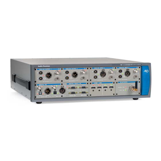
This illustration shows an APx525 in its standard configuration, with a DIO module installed. These specifications cover the analog input and output functions of the Audio Precision APx525 and APx526 analyzers, as well as Audio Precision analyzers branded APx520 and APx521. - Page 20 Characteristic Specifications Supplemental Information ANALOG GENERATOR 2, independent amplitude control Number of Channels Sine, sine split frequency, sine split Option AG52 required for square waves Waveforms phase, sine+DC offset, continuously and DIM test signals swept-sine, square-wave, noise, IMD signals, multi-tone, wave file playback Sine Characteristics Frequency Range (Fs) 0.1 Hz to 80.1 kHz...
- Page 21 Characteristic Specifications Supplemental Information Square Characteristics (requires option AG52) Frequency Range (Fq) 10.0 Hz to 20.1 kHz Same accuracy as sine wave Amplitude Range 0 to 60.0 Vpp, balanced; 0 to 30.0 Vpp, unbalanced Amplitude Accuracy ±0.10 dB [±1.2%] Risetime ≤2.0 μsec Typically <1.7 μsec when Rs ≤200 Ω...
- Page 22 Characteristic Specifications Supplemental Information DIM (requires option AG52) Square / Sine Frequencies 3.15 kHz / 15.0 kHz, “DIM100” or “DIM30” 2.96 kHz / 14.0 kHz, or “DIM-B” 2.96 kHz / 8.0 kHz. “DIM-B8” Mix Ratio 4:1, square to sine, peak-peak Amplitude Range <60 μV to 75.4 Vpp, balanced;...
- Page 23 Characteristic Specifications Supplemental Information Output Related Crosstalk (–130 dB + 0.3 µV) to 20 kHz ANALOG ANALYZER Number of Channels APx525 (and APx520) 2, independently auto-ranging. With option BW52: only Channel 1 is active if input BW setting = 1 MHz APx526 (and APx521) 4, independently auto-ranging.
- Page 24 Characteristic Specifications Supplemental Information Level (Amplitude) Measurement Range Balanced or bridging input < 1 µV to 300 Vrms Unbalanced input < 1 µV to 160 Vrms Accuracy (1 kHz) +15C to +30C ±0.03 dB [±0.35%] 0C to +45C ±0.05 dB [±0.58%] Flatness (1 kHz ref, DC coupling) 10 Hz to 20 kHz ±0.008 dB...
- Page 25 Characteristic Specifications Supplemental Information Level & THD+N Response High-Pass 5 Hz to 500 Hz, or None 1 Hz steps 1 kHz to the selected BW setting, or 100 Hz steps, filter set 1 kHz to 100 kHz, Low-Pass None 1 kHz steps filter set above 100 kHz; very sharp roll-off characteristic exceeds AES-17.
- Page 26 Characteristic Specifications Supplemental Information Frequency Measurement Range <5 Hz to 90 kHz, standard; <5 Hz to 1 MHz with option BW52. must be 5 mV. Accuracy ±(0.0002% + 100 µHz) Resolution 6 digits Phase Measurement Ranges –90 to +270, ±180, or 0 to 360 deg must be ...
-
Page 27: Apx582 Analog I/O Specifications
This illustration shows an APx582 in its standard configuration, with a DIO module installed. These specifications cover the analog input and output functions of the Audio Precision APx582 audio analyzer. The APx582 has 2 analog output channels and 8 analog input chan- nels. - Page 28 Characteristic Specifications Supplemental Information ANALOG GENERATOR 2, independent amplitude control Number of Channels Sine, sine split frequency, sine split Waveforms phase, sine+DC offset, continuously swept-sine, square-wave, noise, IMD signals, multi-tone, wave file playback Sine Characteristics Frequency Range (Fs) 0.1 Hz to 80.1 kHz Setting resolution is typically 45 µHz Frequency Accuracy ±(0.0003% + 100 μHz)
- Page 29 Characteristic Specifications Supplemental Information Square Characteristics Frequency Range (Fq) 10.0 Hz to 20.1 kHz Same accuracy as sine wave Amplitude Range 0 to 60.0 Vpp, balanced; 0 to 30.0 Vpp, unbalanced Amplitude Accuracy ±0.10 dB [±1.2%] Risetime ≤2.0 μsec Typically <1.7 μsec when Rs ≤200 Ω Even Harmonic Content Fq = 10 Hz to 5 kHz ≤–100 dB to at least 80 kHz...
- Page 30 Characteristic Specifications Supplemental Information Square / Sine Frequencies 3.15 kHz / 15.0 kHz, “DIM100” or “DIM30” 2.96 kHz / 14.0 kHz, or “DIM-B” 2.96 kHz / 8.0 kHz. “DIM-B8” Mix Ratio 4:1, square to sine, peak-peak Amplitude Range <60 μV to 75.4 Vpp, balanced; <30 μV to 37.7 Vpp, unbalanced.
- Page 31 Characteristic Specifications Supplemental Information Typically <120 dB to 20 kHz Output Related Crosstalk ANALOG ANALYZER 8, independently auto-ranging Max ADC sample rate = 192 kS/s Number of Channels 160 Vpk, 120 Vdc any input to ground; Maximum Rated Input 0.5 Vpk bnc shields to ground Input Impedance 100 k...
- Page 32 Characteristic Specifications Supplemental Information 1.3 µVrms, 20 kHz BW Typically <8.0 nV / √Hz at 1 kHz Residual Noise (inputs shorted) THD+N Measurement Fundamental Range 5 Hz to 50 kHz Measurement Range 0 to 100% Accuracy ±0.5 dB Residual THD+N ...
- Page 33 Characteristic Specifications Supplemental Information u1 to u9 per IEC-60286 Measurement Range 0 to 20% Accuracy ±0.5 dB 1,2,3 Residual IMD –95 dB0.0018%], 4:1 mix ratio SMPTE & MOD –106 dB0.0005%] ≤ –95 dB [0.0018%] Frequency Measurement Range <5 Hz to 90 kHz must be ...
- Page 34 4 Valid for the balanced input configuration with DC coupling only. With AC coupling, specified performance is invalid below 50 Hz. 5 Maximum low-pass filter frequency is limited by analyzer input bandwidth setting. APx582 Analog I/O Specifications...
-
Page 35: Apx585 Family Analog I/O Specifications
This illustration shows an APx585 in its standard configuration, with a DIO module installed. These specifications cover the analog input and output functions of the Audio Precision APx585 and APx586 audio analyzers. The APx585 has 8 analog output channels and 8 analog input channels;... - Page 36 Characteristic Specifications Supplemental Information ANALOG GENERATOR 8, independent amplitude control Number of Channels Sine, sine split frequency, sine split Waveforms phase, sine+DC offset, continuously swept-sine, square-wave, noise, IMD signals, multi-tone, wave file playback Sine Characteristics Frequency Range (Fs) 5 Hz to 80.1 kHz Setting resolution is typically 45 μHz Frequency Accuracy ±(0.0003 % + 100 μHz)
- Page 37 Characteristic Specifications Supplemental Information Noise Characteristics Shape White (<5 Hz to >80 kHz), Pink (<10 Hz to >80 kHz), IEC 60268-1 or BS EN 50332-1 Amplitude Range 0 to 40.72 Vpp, balanced; Amplitude calibration is approximate 0 to 20.36 Vpp, unbalanced IMD Test Signals SMPTE &...
- Page 38 Characteristic Specifications Supplemental Information Arbitrary 30-pole output filter, scaled The EQ operates on the first two internal Output Equalization so the maximum gain is –1 dB. generator channels, and is disabled for >2 output channels. Source Resistance (Rs) 100 , ±1 % Balanced Grounded, symmetrical 50 , ±2 %...
- Page 39 Characteristic Specifications Supplemental Information Max common mode signal range: Common Mode Rejection 320 mV, 1 V, 3.2 V ranges 70 dB, 5 kHz to 20 kHz ±6 Vpk 50 dB, 5 Hz to 20 kHz 10 V range ±16 Vpk ...
- Page 40 Characteristic Specifications Supplemental Information IMD Measurement Test Signal Compatibility HF tone must be 6 • LF tone SMPTE & MOD Any combination of 40 Hz–1 kHz (LF) and 2 kHz–20 kHz (HF), mixed in any ratio from 1:1 to 10:1 (LF:HF) Any two-tone combination with mean = (F1 + F2)/2.
- Page 41 Characteristic Specifications Supplemental Information Valid only for input bandwidths ≤90k DC Voltage Measurement Input Ranges 0.32 V to 100 V, 10 dB steps ±120 Vdc maximum in 100 V range Accuracy 0.32 V range ±(0.7% reading + 800 µV) 1 V–100 V ranges ±(0.7% reading + 0.1% range) Normal Mode Rejection Typically >...
- Page 42 APx585 Family Analog I/O Specifications...
-
Page 43: Dio Specifications
This illustration shows a stand-alone APx DIO module, model 210. These specifications cover the digital input and output functions of the Audio Precision DIO. The DIO is available as a stand-alone module (models 110 or 210), and in several combination modules, combined with DSIO (models 111 or 211), Bluetooth I/O (model 217) or PDM I/O (model 218). - Page 44 Characteristic Specifications Supplemental Information DIGITAL I/O DIGITAL OUTPUT RELATED: Formats Electrical, unbalanced SPDIF-EIAJ per IEC60958 Electrical, balanced AES-EBU per AES3-1992 Optical Toslink® or equivalent Sample Rate (SR) Range Electrical 27 kS/s to 200 kS/s Usable over the extended range of 16 kS/s to 216 kS/s with degraded waveform fidelity, accuracy, and jitter Optical...
- Page 45 Characteristic Specifications Supplemental Information Sine Characteristics Frequency Range 5 Hz to 0.499 • SR Typically < 0.001 dB Flatness Offset Range To maximum digital code [±1D] Offset limits maximum ac signal Typically < –140 dBFS Harmonics & Spurious Square Characteristics Frequency Range (Fq) 10 Hz to SR / 6 Fq must equal SR / N where N is an...
- Page 46 Characteristic Specifications Supplemental Information DIGITAL INPUT RELATED: Formats Unbalanced SPDIF-EIAJ per IEC 60958, ≤5 Vpp Input typically 75 Ω or ≈8.3 kΩ Balanced AES-EBU per AES3-2003, ≤10 Vpp Input typically 110 Ω or ≈2.5 kΩ Optical Toslink® or equivalent Sample Rate (SR) Range Electrical 27 kS/s to 216 kS/s Typically locks down to 16 kS/s...
- Page 47 Characteristic Specifications Supplemental Information Low-Pass Butterworth (–3 dB) = 1 kHz to 150 kHz, 8- ENBW ≈1.006 • FLP pole Elliptic (–0.01 dB) = 1 kHz to 150 kHz, ENBW ≈(1.012-1.062) • FLP 8-pole; 0.01 dB pass-band ripple; ≤ –60 dB stop-band SR / 2 (Maximum) No filter is implemented, bandwidth –3 dB at ≈0.490 •...
- Page 48 Characteristic Specifications Supplemental Information Frequency Measurement Range < 5 Hz to 0.499 • SR Accuracy ±(0.0003% + 100 µHz) Phase Measurement Ranges –90 to +270, ±180, or 0 to 360 deg Accuracy Typically < 0.001 deg NOTES to SPECIFICATIONS: 1 Sample rate (SR) must be ≥27 kS/s for specified performance. Jitter analyzer set for 700 Hz highpass response per AES3-1992.
-
Page 49: Adio Specifications
NP0020.00021 rev 000 October 2014 This illustration shows a stand-alone APx ADIO module, model 219. These specifications cover the digital input and output functions of the Audio Precision Advanced Digital Input/Output (ADIO). The ADIO is available as a stand-alone module (model 219). - Page 50 Characteristic Specifications Supplemental Information ADVANCED DIGITAL I/O DIGITAL OUTPUT RELATED: Formats Electrical, unbalanced SPDIF-EIAJ per IEC60958 Electrical, balanced AES-EBU per AES3-1992 Optical Toslink® or equivalent Sample Rate (SR) Range Electrical 27 kS/s to 200 kS/s Usable over the extended range of 16 kS/s to 216 kS/s with degraded waveform fidelity, accuracy, and jitter Optical...
- Page 51 Characteristic Specifications Supplemental Information Residual Jitter Unbalanced, Balanced 700 Hz-100 kHz BW ≤600 ps Peak detection 50 Hz-100 kHz BW ≤1.0 ns Peak detection Optical Typically <2.5 ns, SR ≤96 kS/s INTERFACE SIGNAL IMPAIRMENTS Variable Rise/Fall Time Range 12 ns to 100 ns 1 ns typical resolution Accuracy ±(10% + 2 ns)
- Page 52 Characteristic Specifications Supplemental Information Common Mode Signal (Bal only) Waveform Sine Frequency Range 20 Hz to 100 kHz Amplitude Range 0 to 20.0 Vpp, 20 mV steps: ±(10% + 50 mV) EMBEDDED OUTPUT SIGNAL RELATED: Sine, sine split frequency, sine split 8–24 bit word width, triangular PDF Waveforms phase, sine+DC offset, continuously...
- Page 53 Characteristic Specifications Supplemental Information Tone Pair Mean Range 2.5 kHz to (0.499 • SR – F / 2) or = (F1 + F2)/2 diff mean 20 kHz, whichever is lower Tone Pair Difference Range 80 Hz to 2.0 kHz = |F2-F1|; diff must be ...
- Page 54 Characteristic Specifications Supplemental Information Jitter Measurement Range 0-4.0 UI at F ≤500 Hz Detection Peak, RMS, or Average “Peak” detection must be used for residual measurements per AES3. “Average” detection is recommended for jitter response measurements. Bandwidth Low Limit 50 Hz or 700 Hz (AES3) High Limit Variable from 1 kHz to 150 kHz in 0.1 kHz steps, Butterworth or Elliptic...
- Page 55 Characteristic Specifications Supplemental Information THD+N Measurement Fundamental Range 5 Hz to 0.49 • SR or 50 kHz, Tuning can be set to track measured fre- whichever is lower quency, generator setting or fixed Measurement Range 0 to 100% Accuracy ±0.5 dB Typically <...
- Page 56 Characteristic Specifications Supplemental Information IMD Measurement Test Signal Compatibility HF tone must be 6 • LF tone SMPTE & MOD Any combination of 40 Hz–1 kHz (LF) and 2 kHz–20 kHz (HF), mixed in any ratio from 1:1 to 10:1 (LF:HF) Any two-tone combination with mean = (F1 + F2)/2 mean...
- Page 57 Characteristic Specifications Supplemental Information NOTES to SPECIFICATIONS: 1 System specification including contributions from both generator and analyzer subject to the following conditions: (A) SR = 27 kS/s to 200 kS/s, (B) interface signal ≥1.5 Vpp Bal or ≥300 mVpp Unbal, (C) rise-time ≤20 nsec, and (D) no impairments.
- Page 58 APx Advanced Digital I/O Module: Specifications...
-
Page 59: Dsio Specifications
This illustration shows a stand-alone APx DSIO module, model 216. These specifications cover the digital serial input and output functions of the Audio Precision DSIO. The DSIO is available as a stand-alone module (model 216), and in a combination mod- ule, combined with DIO (models 111 or 211). - Page 60 Characteristic Specifications Supplemental Information Functional characteristics Channels 1 data line, TDM 1, 2, 4, 8 or 16 Time division multiplexing (TDM) Multiple data lines 1, 2, 4 or 8 up to 4 data lines; 2 channels on each line by TDM S, DSP, custom (left/right justified, Data formats one bit/one subframe/50% duty cycle...
- Page 61 Characteristic Specifications Supplemental Information DC characteristics, no load 1.8 volt setting High level input Minimum 1.0 V Low level input Maximum 0.8 V High level output Minimum 1.6 V Low level output Maximum 0.1 V Absolute range Minimum –0.5 V Maximum 5.5 V 2.5 volt setting...
- Page 62 Characteristic Specifications Supplemental Information 3.3 volt setting High level input Minimum 1.8 V Low level input Maximum 1.5 V High level output Minimum 3.0 V Low level output Maximum 0.1 V Absolute range Minimum –0.5 V Maximum 5.5 V Input/Output impedance 50 Ω, nominal All Outputs 10 kΩ, nominal...
- Page 63 Characteristic Specifications Supplemental Information Clock Jitter (Advanced Master Clock required) Jitter Measurement Range 0 to 650 ns Detection Peak, RMS, or Average “Average” detection is recommended for jitter response measurements. Bandwidth Low Limit 50 Hz or 700 Hz High Limit Variable from 1 kHz to 150 kHz in 0.1 kHz steps, Butterworth or Elliptic response...
- Page 64 Characteristic Specifications Supplemental Information NOTE to SPECIFICATIONS 1 System specification including contributions from both generator and analyzer subject to the following condition: Bit Clock 192 kHz. APx Digital Serial I/O Module: Specifications...
-
Page 65: Hdmi+Arc Specifications
October 2013 This illustration shows the HDMI+ARC module, model 214. These specifications cover the input and output functions of the Audio Precision HDMI+ARC (High Definition Multimedia Interface plus Audio Return Channel) I/O module. HDMI+ARC is available as a stand-alone module (models 114 or 214). - Page 66 Characteristic Specifications Supplemental Information 1.3a + ARC. ARC (Audio Return Channel) imple- Revision mented per HDMI 1.4a Device Connections SOURCE Typically connects to the sink input of The video is an internally generated sin- a DUT. gle color screen or the signal applied to the AUX IN connector.
- Page 67 Characteristic Specifications Supplemental Information HDMI ARC Tx configuration: ARC ARC link can be negotiated or forced on. CEC (ARC connectors) CEC implementation per HDMI 1.4a. User can manually send a CEC ping HDMI ARC Rx configuration: ARC or arbitrary CEC message to any of CEC implementation per HDMI 1.4a.
- Page 68 Characteristic Specifications Supplemental Information EMBEDDED OUTPUT SIGNAL RELATED: Sine, sine split frequency, sine split 8–24 bit word width, triangular PDF Waveforms phase, sine+DC offset, continuously dither. swept-sine, square-wave, noise, IMD signals, multi-tone, constant value, walking ones/zeros, bittest random, wave file playback. Sine Characteristics Frequency Range 5 Hz to 0.499 •...
- Page 69 Characteristic Specifications Supplemental Information Typically < –150 dBFS 1, 3 Residual IMD DIGITAL INPUT RELATED: Formats Single mode ≤1.5 Vpp Input R is nominally 55 Ω Dual mode ≤1.5 Vpp Input R is nominally 30 Ω 22 kS/s–216 kS/s Typically locks down to 16 kS/s Sample Rate Range EMBEDDED INPUT SIGNAL RELATED: Level (Amplitude) Measurement...
- Page 70 Characteristic Specifications Supplemental Information Any two-tone combination with mean = (F1 + F2)/2 mean frequency of 2.5 kHz–50 kHz and a = |F2 - F1| diff difference frequency of 80 Hz–2.0 kHz must be 6 • F mean diff IMD Measured SMPTE Amplitude modulation of HF tone.
-
Page 71: Bluetooth Specifications
November 2012 This illustration shows the stand-alone Bluetooth module, model 213. These specifications cover the digital input and output functions of the Audio Precision Blue- tooth interface. Bluetooth is available as a stand-alone module (model 213), and in a combina- tion module, combined with DIO (model 217). - Page 72 Characteristic Specifications Supplemental Information Bluetooth Core Version 2.1+EDR Profiles/Roles Supported A2DP Source With APx-BT-WB hardware module, there is a potential +/- 1 sample inter- channel phase error in A2DP Source or Sink operation. A2DP Sink See note above. HFP Audio Gateway HFP Hands-Free HSP Audio Gateway HSP Headset...
-
Page 73: Pdm Specifications
October 2013 This illustration shows the stand-alone PDM module, model 215. These specifications cover the digital input and output functions of the Audio Precision PDM interface. PDM is available as a stand-alone module (model 215), and in a combination mod- ule, combined with DIO (model 218). -
Page 74: Technical Specifications
Technical Specifications Parameter Symbol Test Conditions Unit TRANSMITTER Decimated Rate Bit Clock Rate Master or slave mode 0.128 24.576 INTERPOLATION FILTER 16, 16.67, 21.33, 24, 25, 32, 33.33, 37.5, 42.67, 48, 50, 64, 66.67, 75, Interpolation Ratio (F INTR 85.33, 96, 100, 128, 150, 192, 200, 256, 300, 384, 400, 512, 500, 768, 800 Passband Frequency Range... - Page 75 Parameter Symbol Test Conditions Unit @MIL; F = 48 kHz; per AES17 Dynamic Range MODULATOR: ORDER 5, 64x OSR Overload Point 1 kHz –9.4 dBFS @OLP; BW = 0.45 F Total Harm. Dist. + Noise –116 @OLP; BW = 0.45 F Signal-to-Noise Ratio @MIL;...
- Page 76 Parameter Symbol Test Conditions Unit MODULATOR: ORDER 4, 512x OSR Overload Point 1 kHz –8.2 dBFS @OLP; BW = 0.45 F Total Harm. Dist. + Noise –130 @OLP; BW = 0.45 F Signal-to-Noise Ratio @MIL; F = 48 kHz; per AES17 Dynamic Range MODULATOR: ORDER 5, 512x OSR Overload Point...
- Page 77 Parameter Symbol Test Conditions Unit LOGIC LEVEL Interface Voltage 1.80 3.30 Resolution 0.01 Accuracy ±0.05 OUTPUT CHARACTERISTICS = 0.5 mA 0.7 • V Output Voltage High LOAD = 0.5 mA 0.3 • V Output Voltage Low LOAD VDD OUTPUT DC Voltage 0.80 3.60 Resolution...
- Page 78 Timing Characteristics Parameter Description Unit PDM TRANSMITTER Clock period (master or slave mode) 7813 CLKTX Data hold time / 2-30 Data setup time CLKTX PDM RECEIVER Clock period (master or slave mode) 7813 CLKRX Data hold time, rising edge Data hold time, falling edge Data setup time BITCLK DATA TX...
-
Page 79: Amc Specifications
AMC Advanced Master Clock Rear Panel Sync, Trigger and Ref I/O specifications with APx500 v4.0 or higher measurement software as fitted in APx52x, 555, and 58x audio analyzers NP0020.00023 rev 000 October 2014 This illustration shows a section of the APx rear panel, focusing on the Auxiliary I/O and the Sync, Trigger and DARS reference connections for the AMC. - Page 80 Characteristic Specifications Supplemental Information REAR PANEL I/O Auxiliary Digital Control Output 8 bits Typically 0-5V, 9-pin male D-sub Input 8 bits Internal pull-up, 9-pin female D-sub Sync Input Signal Compatibility Square or Sine Voltage Range 0.8 Vpp to 5.0 Vpp >10 kΩ, AC coupled Frequency Range 4 kHz to 50 MHz, square;...
- Page 81 Characteristic Specifications Supplemental Information Trigger Input Voltage Range –0.5 V to +5.5 V Threshold Level +0.8 to +3.6 V, 0.1 V steps ≈10 kΩ, DC coupled, + or – edge selectable Minimum Pulse Width Typically 20 ns Trigger Output Trigger Sources Analog Sine Generator, Audio Gener- ator, and Jitter Generator Amplitude (VH)
- Page 82 APx AMC Sync, Trigger and Ref Input/Output Specifications...
-
Page 83: General And Environmental Specifications
Emissions and immunity levels are influ- EN 61326-1:2006. Complies with EC enced by the quality of interface and sig- Council Directives 2004/108/EC and nal cables attached to the unit. 93/68/EEC Compliance was demonstrated using Audio Precision cables APx52x and 58x Families General and Environmental... - Page 84 Characteristic Specifications Supplemental Information IEC 61010-1:2001 / Equipment Class I, Safety EN 61010-1:2001, Installation Category II, CAN/CSA-C22.2 No. 61010-1-04, and Pollution Degree 2, UL Std No. 61010-1 (2nd Edition). Measurement Category I Complies with EC Council Directives 2006/95/EC and 93/68/EEC Dimensions Width 432 mm (17.0 inches)
Need help?
Do you have a question about the APx52 series and is the answer not in the manual?
Questions and answers