Table of Contents
Advertisement
Advertisement
Table of Contents

Related Manuals for Audio Precision AP 52 B Series


Summary of Contents for Audio Precision AP 52 B Series
- Page 4 APx52x and 58x B Series families of audio analyzers Installation Instructions and Specifications B Series APx525 with DIO, PDM, DSIO and Bluetooth options November, 2019...
- Page 5 DTS © Digital Surround is trademark of DTS, Inc. The Bluetooth® word mark and logos are registered trademarks owned by the Blue- tooth SIG, Inc. and any use of such marks by Audio Precision is under license. Other trademarks and trade names are those of their respective owners.
- Page 6 CD players. ap.com Visit the Audio Precision Web site at ap.com for APx support information. APx resources are available at ap.com. You can also contact our Technical Support staff at techsupport@ap.com, or by telephoning 503-627-0832 ext. 4, or 800-231-7350 ext. 4 (toll...
-
Page 8: Table Of Contents
Table of Contents Safety ..............i Sécurité... - Page 9 Table of Contents Bluetooth specifications ............73 PDM 16 specifications .
-
Page 10: Safety
Servicing should be performed only by a quali- (IEC 1010-1) requires that measuring circuit terminals used fied technician or an authorized Audio Precision distributor. for voltage or current measurement be marked to indicate Do NOT defeat the safety ground connection. This equip- their Measurement Category. - Page 11 Do NOT substitute parts or make any modifications with- out the written approval of Audio Precision. Doing so may create safety hazards. Using this product in a manner not specified by Audio Precision can result in a safety hazard.
-
Page 12: Sécurité
L’entretien devrait être effectué uniquement par un tech- MENT par des fusibles de même valeur et type, comme nicien qualifié ou un distributeur Audio Precision agréé. indiqué sur le panneau arrière de l’instrument et précisé à la Ne PAS dérouter le branchement de la mise à la terre de page 8 de ce livret. - Page 13 Ne PAS remplacer de pièces ou effectuer de modifications AVERTISSEMENT!—Ce symbole vous informe d’une sit- sans l’approbation écrite d’Audio Precision. Si c’est le cas, uation potentiellement dangereuse, par exemple, la présence il pourrait y avoir des risques pour la sécurité. Utiliser ce d’une tension dangereuse qui pourrait présenter un risque de...
- Page 14 être raccordées à un système protecteur de mise à la terre externe. Avis de non-responsabilité Audio Precision déconseille fortement l’utilisation de ses produits d’une manière non spécifiée par le fabricant. Une telle utilisation pourrait annuler toute garantie, endom- mager l’équipement ou présenter un risque de sécurité...
- Page 15 Sécurité APx52x/58x B Series Audio Analyzers: Sécurité...
-
Page 16: Seguridad
Audio Precision. instrumento y que se explica en la página 12 de este folleto. NO modifique la conexión de seguridad a tierra. Este International Electrotechnical Commission [La Comisión... - Page 17 NO reemplace partes ni haga modificaciones sin la aproba- condición potencialmente peligrosa, tal como la presencia ción por escrito de Audio Precision. Hacerlo podría causar de voltaje peligroso que pudiera representar un riesgo de riesgos de seguridad. El uso de este producto en una manera descarga eléctrica.
- Page 18 (aterrizada). Exención de responsabilidad Audio Precision advierte contra el uso de este producto de una manera no especificada por el fabricante. El hecho de no hacerlo de la manera indicada invalidaría las garantías, causaría daño al equipo, o representaría un riesgo de seguri-...
- Page 19 Seguridad APx52x/58x B Series Audio Analyzers: Seguridad...
-
Page 20: Installation
All APx systems use the same award-winning measure- The APx KeyBox must be programmed with your ana- ment software, APx500. lyzer’s serial number at the Audio Precision factory, and APx “B Series” analyzers cannot be used with any other APx analyzer. You may... - Page 21 Installation PC system requirements Please view the current APx PC Minimum System Solu- tions document on our Web site at www.ap.com. This infor- The APx500 measurement software version 4.1 and later mation will help you to determine the adequacy of a can be very demanding of the personal computer (PC) run- particular PC for high-bandwidth, high-channel count mea- ning the APx software.
- Page 22 APx500 software. driver. Select “Install the software automatically.” Win- Guest users are not supported. dows will find the Audio Precision driver software installed with APx500 and connect to the instrument. Connecting the instrument to your PC...
- Page 23 Installation Removing and installing mains fuses To remove the mains fuse carrier module, refer to the fig- ures below and proceed as follows: Power entry module Fuse carrier removal Remove the mains power supply cord from the connector on the power entry module, located on the instrument rear panel.
-
Page 24: Installation (Fr)
Installation (Fr) Logiciel « B Series »), vous devez installer un dispositif APx Key- Box authentifié au connecteur Software Options sur le pan- Tous les systèmes APx utilisent le même logiciel de mesure neau arrière de l’analyseur. lauréat, soit APx500. Le dispositif APx KeyBox doit être programmé... - Page 25 Installation (Fr) Le numéro de série de l’analyseur se trouve sur l’étiquette Demandes de mesures élevées Les demandes de mesures élevées (bandes passantes de de configuration à l’arrière de l’analyseur et sur l’étiquette mesure de plus de 90 kHz, nombre de canaux de plus de 2) d’étalonnage sur le bord avant du panneau supérieur.
- Page 26 Brancher l’instrument avant d’installer le logiciel peut tion automatique du logiciel). Windows trouvera le logiciel entraîner la sélection du mauvais pilote USB pour l’instru- pilote Audio Precision installé avec APx500 et branché à ment. l’instrument. Sélection de pilote USB Lancez APx500 en cliquant deux fois sur le raccourci.
- Page 27 Installation (Fr) rera et, peu de temps après, affichera l’écran d’accueil. Con- Pour retirer le module porte-fusibles secteurs, consultez les sultez le manuel de l’utilisateur du logiciel APx500 pour de figures ci-dessous et procédez comme suit : plus amples renseignements à propos des prises de mesures. Un exemplaire du manuel de l’utilisateur du logi- ciel APx500 est inclus avec votre instrument.
-
Page 28: Instalación
Todos los sistemas APx utilizan el mismo software lau- El APx KeyBox debe ser programado con el número de reado, APx500. serie de su analizador en la fábrica de Audio Precision, y no Analizadores APx “B Series” puede ser usado con ningún otro Analizador APx. Puede requerir códigos de autorización para habilitar el software... - Page 29 2.5 GHz. Un procesador AMD [APx500 application disc], puede descargar APx500 del similar también funcionará. sitio web de Audio Precision en www.ap.com. • Por lo menos 8 GB de RAM. Se recomienda 16 GB NOTA: Usted debe tener derechos de adminis- RAM.
- Page 30 Instalación hardware, el APx500 le mostrará el siguiente cuadro de Selección del controlador del USB diálogo: El software de medición se comunica con el instrumento utilizando una interconexión USB 2.0. Una vez que el soft- ware se haya instalado correctamente, conecte un extremo del cable USB a un puerto USB 2.0 en la PC, y el otro extremo al puerto de PC INTERFACE [INTERFAZ de la PC] en la parte posterior del instrumento.
- Page 31 Instalación Ejecute APx500 haciendo doble clic en el acceso directo Para extraer los fusibles del módulo portador de fusibles de instalado. Con el instrumento ya conectado, se le podría fuente de alimentación, consulte las figuras a continuación pedir actualizar el firmware del instrumento durante la pri- y proceda de la siguiente manera: mera ejecución del software de medición.
- Page 32 Instalación Conecte el cable de alimentación desde una salida de fuente de alimentación hacia el conector de cable de alimentación en el panel posterior del instrumento. APx52x/58x B Series Audio Analyzers: Instalación...
- Page 33 Instalación APx52x/58x B Series Audio Analyzers: Instalación...
-
Page 34: Abbreviations, Terms And Symbols
Abbreviations, Terms and Symbols used in the following specifications ADC or A/D ..Analog to Digital converter or conversion. BW ....Bandwidth or Measurement Bandwidth, nominally at –3 dB; a single number indicates only the upper limit. - Page 35 Abbreviations, Terms and Symbols...
-
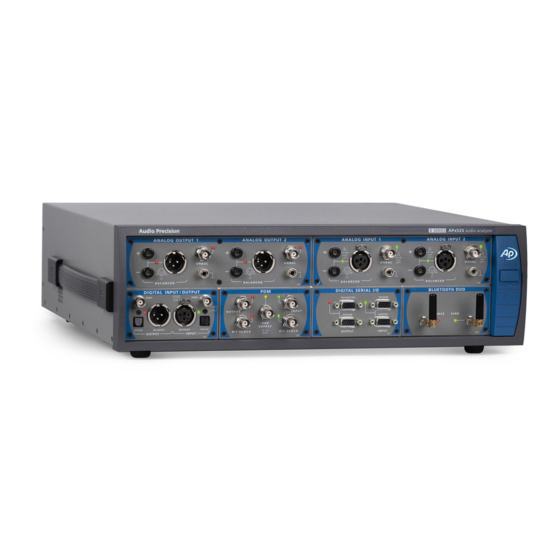
Page 36: Apx525 Family Analog I/O Specifications
December 2018 NP0020.00032 r000 This illustration shows an APx525 B Series in its standard configuration, with a DIO module installed. These specifications cover the analog input and output functions of the Audio Precision APx525 and APx526 B Series analyzers. The APx525 has 2 analog output channels and 2 analog input channels. - Page 37 Characteristic Specifications Supplemental Information ANALOG GENERATOR 2, independent amplitude control Number of Channels Sine, sine split frequency, sine split Option AG52 required for square waves Waveforms phase, sine+DC offset, continuously and DIM test signals swept-sine, square-wave, noise, IMD signals, multi-tone, wave file playback Sine Characteristics Frequency Range (Fs) 0.1 Hz to 80.1 kHz...
- Page 38 Characteristic Specifications Supplemental Information Amplitude Range 0 to 60.0 Vpp, balanced; 0 to 30.0 Vpp, unbalanced Amplitude Accuracy ±0.10 dB [±1.2%] Risetime ≤2.0 μsec Typically <1.7 μsec when Rs ≤200 Ω Even Harmonic Content Fq = 10 Hz to 5 kHz ≤–100 dB to at least 80 kHz Fq = 5 kHz to 20 kHz ≤–90 dB to at least 80 kHz...
- Page 39 Characteristic Specifications Supplemental Information DIM (requires option AG52) Square / Sine Frequencies 3.15 kHz / 15.0 kHz, “DIM100” or “DIM30” 2.96 kHz / 14.0 kHz, or “DIM-B” 2.96 kHz / 8.0 kHz. “DIM-B8” Mix Ratio 4:1, square to sine, peak-peak Amplitude Range <60 μV to 75.4 Vpp, balanced;...
- Page 40 Characteristic Specifications Supplemental Information Output Related Crosstalk (–130 dB + 0.3 µV) to 20 kHz ANALOG ANALYZER Number of Channels APx525 (and APx520) 2, independently auto-ranging. APx526 (and APx521) 4, independently auto-ranging. With option BW52: only Channels 1 and 2 are active if BW setting = 250 kHz, 500 kHz or 1 MHz 230 Vpk, 160 Vdc, any input to...
- Page 41 Characteristic Specifications Supplemental Information Level (Amplitude) Measurement Range Balanced or bridging input < 1 µV to 300 Vrms Unbalanced input < 1 µV to 160 Vrms Accuracy (1 kHz) +15C to +30C ±0.03 dB [±0.35%] 0C to +45C ±0.05 dB [±0.58%] Flatness (1 kHz ref, DC coupling) 10 Hz to 20 kHz ±0.008 dB...
- Page 42 Characteristic Specifications Supplemental Information Bandwidth Limiting Filters High-Pass DC coupling AC (< 10 Hz) AC coupling Response is 2-pole via a combination of analog and digital filters, and is typically –3 dB at 4.1 Hz Butterworth (–3 dB) = 10 Hz to 90 kHz, 4-pole; 10 Hz to 1 MHz (BW52) Elliptic (–0.01 dB) = 10 Hz to 90 kHz,...
- Page 43 Characteristic Specifications Supplemental Information IMD Measurement Test Signal Compatibility LF tone must be 1/6 • HF tone. SMPTE & MOD Any combination of 40 Hz–1 kHz (LF) and 240 Hz–60 kHz (HF), mixed in any ratio from 1:1 to 10:1 (LF:HF) DFD &...
- Page 44 Characteristic Specifications Supplemental Information Phase Measurement Ranges –90 to +270, ±180, or 0 to 360 deg must be 5 mV with DC coupling, Accuracy ±0.2 deg, 5 Hz to 5 kHz; ±0.8 deg, 5 kHz to 20 kHz; both channels. Accuracy degrades ±2.0 deg, 20 kHz to 50 kHz below 50 Hz with AC coupling.
- Page 45 Characteristic Specifications Supplemental Information APx525/526 B Series Audio Analyzers: Analog I/O Specifications...
-
Page 46: Apx582 Analog I/O Specifications
This illustration shows an APx582 B Series in its standard configuration, with a DIO module installed. These specifications cover the analog input and output functions of the Audio Precision B Series APx582 audio analyzer. The APx582 has 2 analog output channels and 8 analog input channels. - Page 47 Characteristic Specifications Supplemental Information ANALOG GENERATOR 2, independent amplitude control Number of Channels Sine, sine split frequency, sine split Waveforms phase, sine+DC offset, continuously swept-sine, square-wave, noise, IMD signals, multi-tone, wave file playback Sine Characteristics Frequency Range (Fs) 0.1 Hz to 80.1 kHz Setting resolution is typically 45 µHz Frequency Accuracy ±(0.0003% + 100 μHz)
- Page 48 Characteristic Specifications Supplemental Information Square Characteristics Frequency Range (Fq) 0.1 Hz to 30 kHz Same accuracy as sine wave Amplitude Range 0 to 60.0 Vpp, balanced; 0 to 30.0 Vpp, unbalanced Amplitude Accuracy ±0.10 dB [±1.2%] Risetime ≤2.0 μsec Typically <1.7 μsec when Rs ≤200 Ω Even Harmonic Content Fq = 10 Hz to 5 kHz ≤–100 dB to at least 80 kHz...
- Page 49 Characteristic Specifications Supplemental Information Square / Sine Frequencies 3.15 kHz / 15.0 kHz, “DIM100” or “DIM30” 2.96 kHz / 14.0 kHz, or “DIM-B” 2.96 kHz / 8.0 kHz. “DIM-B8” Mix Ratio 4:1, square to sine, peak-peak Amplitude Range <60 μV to 75.4 Vpp, balanced; <30 μV to 37.7 Vpp, unbalanced.
- Page 50 Characteristic Specifications Supplemental Information Output Related Crosstalk (–130 dB+0.3 µV) to 20 kHz ANALOG ANALYZER 8, independently auto-ranging Number of Channels 160 Vpk, 120 Vdc any input to ground; Maximum Rated Input 0.5 Vpk bnc shields to ground Input Impedance Balanced 100 k...
- Page 51 Characteristic Specifications Supplemental Information 1.3 µVrms, 20 kHz BW Typically <8.0 nV / √Hz at 1 kHz Residual Noise (inputs shorted) THD+N Measurement Fundamental Range 5 Hz to 90 kHz Measurement Range 0 to 100% Accuracy ±0.5 dB Residual THD+N ...
- Page 52 Characteristic Specifications Supplemental Information Arbitrary 30-pole input filter The EQ operates on any selected ana- Input Equalization lyzer input channels. IMD Measurement Test Signal Compatibility LF tone must be 1/6 • HF tone. SMPTE & MOD Any combination of 40 Hz–1 kHz (LF) and 240 Hz–60 kHz (HF), mixed in any ratio from 1:1 to 10:1 (LF:HF) DFD &...
- Page 53 Phase Measurement Ranges –90 to +270, ±180, or 0 to 360 deg Accuracy ±0.25 deg, 5 Hz to 5 kHz; Vin must be ≥5 mV, all channels ±1.0 deg, 5 kHz to 20 kHz; ±2.5 deg, 20 kHz to 50 kHz Resolution 0.001 deg Valid only for input bandwidths ≤90k...
-
Page 54: Apx585 Family Analog I/O Specifications
This illustration shows an APx585 B Series in its standard configuration, with a DIO module installed. These specifications cover the analog input and output functions of the Audio Precision B Series APx585 and APx586 audio analyzers. The APx585 has 8 analog output channels and 8 analog input channels;... - Page 55 Characteristic Specifications Supplemental Information ANALOG GENERATOR 8, independent amplitude control Number of Channels Sine, sine split frequency, sine split Waveforms phase, sine+DC offset, continuously swept-sine, square-wave, noise, IMD signals, multi-tone, wave file playback Sine Characteristics Frequency Range (Fs) 5 Hz to 80.1 kHz Setting resolution is typically 45 μHz Frequency Accuracy ±(0.0003 % + 100 μHz)
- Page 56 Characteristic Specifications Supplemental Information Noise Characteristics Shape White (<5 Hz to >80 kHz), Pink (<10 Hz to >80 kHz), IEC 60268-1 or BS EN 50332-1 Amplitude Range 0 to 40.72 Vpp, balanced; Amplitude calibration is approximate 0 to 20.36 Vpp, unbalanced IMD Test Signals SMPTE &...
- Page 57 Characteristic Specifications Supplemental Information Spurious Content Typically <–100 dB Arbitrary 30-pole output filter The EQ operates on the first two internal Output Equalization generator channels, and is disabled for >2 output channels. Source Resistance (Rs) 100 , ±1 % Balanced Grounded, symmetrical 50 , ±2 % Unbalanced...
- Page 58 Characteristic Specifications Supplemental Information Max common mode signal range: Common Mode Rejection 70 dB, 5 kHz to 20 kHz 320 mV, 1 V, 3.2 V ranges ±6 Vpk 50 dB, 5 Hz to 20 kHz 10 V range ±16 Vpk ...
- Page 59 Characteristic Specifications Supplemental Information Bandwidth Limiting Filters High-Pass DC coupling AC (< 10 Hz) AC coupling Response is 2-pole via a combination of analog and digital filters, and is typically –3 dB at 4.1 Hz Butterworth (–3 dB) = 10 Hz to 90 kHz, 4-pole Elliptic (–0.01 dB) = 10 Hz to 90 kHz;...
- Page 60 Characteristic Specifications Supplemental Information IMD Measurement Test Signal Compatibility LF tone must be 1/6 • HF tone. SMPTE & MOD Any combination of 40 Hz–1 kHz (LF) and 240 Hz–60 kHz (HF), mixed in any ratio from 1:1 to 10:1 (LF:HF) DFD &...
- Page 61 Valid only for input bandwidths ≤90k DC Voltage Measurement Input Ranges 0.32 V to 100 V, 10 dB steps ±120 Vdc maximum in 100 V range Accuracy 0.32 V range ±(0.7% reading + 800 µV) 1 V–100 V ranges ±(0.7% reading + 0.1% range) Normal Mode Rejection Typically >...
-
Page 62: Dio Specifications
December, 2018 This illustration shows an APx DIO module, model 240. These specifications cover the digital input and output functions of the Audio Precision DIO. The DIO is available as a stand-alone module (models 240). The APx DIO provides balanced digital input and output compatible with AES3, AES/EBU and IEC60958-4, on XLR connectors;... - Page 63 Characteristic Specifications Supplemental Information DIGITAL I/O DIGITAL OUTPUT RELATED: Formats Electrical, unbalanced SPDIF-EIAJ per IEC60958 Electrical, balanced AES-EBU per AES3-1992 Optical Toslink® or equivalent Sample Rate (SR) Range Electrical 27 kS/s to 200 kS/s Usable over the extended range of 16 kS/s to 216 kS/s with degraded waveform fidelity, accuracy, and jitter Optical...
- Page 64 Characteristic Specifications Supplemental Information Sine Characteristics Frequency Range 5 Hz to 0.499 • SR Typically < 0.001 dB Flatness Offset Range To maximum digital code [±1D] Offset limits maximum ac signal Typically < –140 dBFS Harmonics & Spurious Square Characteristics Frequency Range (Fq) 10 Hz to SR / 6 Fq must equal SR / N where N is an...
- Page 65 Characteristic Specifications Supplemental Information Multitone, Wave File Playback Sample Rate (SR) 8 kS/s to 216 kS/s Maximum File Size 32 MSample Flatness (1 kHz ref) Typically <0.001 dB to 0.499*SR Spurious Content Typically <–140 dBFS DIGITAL INPUT RELATED: Formats Unbalanced SPDIF-EIAJ per IEC 60958, ≤5 Vpp Input typically 75 Ω...
- Page 66 Characteristic Specifications Supplemental Information Bandwidth Limiting Filters (audio signals) High-Pass DC coupling AC (<10 Hz) AC coupling –3 dB at 4.1 Hz Butterworth (–3 dB) = 10 Hz to 100 kHz, 4-pole Elliptic (–0.01 dB) = 10 Hz to 100 kHz, 5-pole;...
- Page 67 Characteristic Specifications Supplemental Information IMD Measured SMPTE Amplitude modulation of HF tone Measurement BW is ≈40–750 Hz d2, d3, d2+d3, or d2+d3+d4+d5 Use “d2+d3” for measurements per IEC-60268 d2, d3, d2+d3, or d2+d3+d4+d5 Use “d2+d3” for measurements per IEC-60268 CCIF d2 only “CCIF”...
-
Page 68: Adio Specifications
NP0020.00041 rev 000 December, 2018 This illustration shows an APx ADIO module, model 238. These specifications cover the digital input and output functions of the Audio Precision Advanced Digital Input/Output (ADIO). The ADIO is available as a stand-alone module (model 238). - Page 69 Characteristic Specifications Supplemental Information ADVANCED DIGITAL I/O DIGITAL OUTPUT RELATED: Formats Electrical, unbalanced SPDIF-EIAJ per IEC60958 Electrical, balanced AES-EBU per AES3-1992 Optical Toslink® or equivalent Sample Rate (SR) Range Electrical 27 kS/s to 200 kS/s Usable over the extended range of 16 kS/s to 216 kS/s with degraded waveform fidelity, accuracy, and jitter Optical...
- Page 70 Characteristic Specifications Supplemental Information Residual Jitter Unbalanced, Balanced 700 Hz-100 kHz BW ≤600 ps Peak detection 50 Hz-100 kHz BW ≤1.0 ns Peak detection Optical Typically <2.5 ns, SR ≤96 kS/s INTERFACE SIGNAL IMPAIRMENTS Variable Rise/Fall Time Range 12 ns to 100 ns 1 ns typical resolution Accuracy ±(10% + 2 ns)
- Page 71 Characteristic Specifications Supplemental Information Common Mode Signal (Bal only) Waveform Sine Frequency Range 20 Hz to 100 kHz Amplitude Range 0 to 20.0 Vpp, 20 mV steps: ±(10% + 50 mV) EMBEDDED OUTPUT SIGNAL RELATED: Sine, sine split frequency, sine split 8–24 bit word width, triangular PDF Waveforms phase, sine+DC offset, continuously...
- Page 72 Characteristic Specifications Supplemental Information IMD Test Signals SMPTE & MOD Lower Frequency (LF) 40 Hz to 1.00 kHz LF tone must be 1/6 • HF tone. SMPTE Upper Frequency (HF) 2 kHz to (0.499 • SR) or 60 kHz, whichever is lower MOD Upper Frequency (HF) 240 Hz to (0.499 •...
- Page 73 Characteristic Specifications Supplemental Information Input Amplitude Measurement Unbalanced 0 to 2.50 Vpp, ±(5% + 6 mV) Balanced 0 to 8.0 Vpp, ±(5% + 25 mV) Jitter Measurement Range 0-4.0 UI at F ≤500 Hz Detection Peak, RMS, or Average “Peak” detection must be used for residual measurements per AES3.
- Page 74 Characteristic Specifications Supplemental Information Residual Jitter 700 Hz - 100 kHz BW ≤600 ps 50 Hz - 100 kHz BW ≤1.0 ns Spurious products are typically Jitter Spectrum –40 dBc (below jitter signal) or –60 dBUI, whichever is larger. Arbitrary 30-pole input filter The EQ operates on any selected ana- Input Equalization lyzer input channels.
- Page 75 Characteristic Specifications Supplemental Information Bandwidth Limiting Filters (audio signals) High-Pass DC coupling AC (<10 Hz) AC coupling –3 dB at 4.1 Hz Butterworth (–3 dB) = 10 Hz to 100 kHz, 4-pole Elliptic (–0.01 dB) = 10 Hz to 100 kHz, 5-pole;...
- Page 76 Characteristic Specifications Supplemental Information IMD Measured SMPTE Amplitude modulation of HF tone Measurement BW is typ. 40–500 Hz xxx d2, d3, d2+d3, or d2+d3+d4+d5 Use “d2+d3” for measurements per IEC-60268 d2, d3, d2+d3, or d2+d3+d4+d5 Use “d2+d3” for measurements per IEC-60268 CCIF d2 only...
- Page 77 APx ADIO Module for B Series: Specifications...
-
Page 78: Dsio Specifications
December, 2018 This illustration shows an APx DSIO module, model 237. These specifications cover the digital serial input and output functions of the Audio Precision DSIO. The DSIO is available as a stand-alone module (model 237). The Digital Serial Input/Output (or DSIO) option provides a flexible chip- or board-level serial input and output interface. - Page 79 Characteristic Specifications Supplemental Information Functional characteristics Channels 1 data line, TDM 1, 2, 4, 6, 8 or 16 Time division multiplexing (TDM) Multiple data lines 1, 2, 4, 6 or 8 up to 4 data lines; 2 channels on each line by TDM Data formats S, DSP, custom (left/right justified,...
- Page 80 Characteristic Specifications Supplemental Information DC characteristics, no load 1.8 volt setting High level input Minimum 1.0 V Low level input Maximum 0.8 V High level output Minimum 1.6 V Low level output Maximum 0.1 V Absolute range Minimum –0.5 V Maximum 5.5 V 2.5 volt setting...
- Page 81 Characteristic Specifications Supplemental Information 3.3 volt setting High level input Minimum 1.8 V Low level input Maximum 1.5 V High level output Minimum 3.0 V Low level output Maximum 0.1 V Absolute range Minimum –0.5 V Maximum 5.5 V Input/Output impedance 50 Ω, nominal All Outputs 10 kΩ, nominal...
- Page 82 Characteristic Specifications Supplemental Information Clock Jitter (Advanced Master Clock required) Jitter Measurement Range 0 to 650 ns Detection Peak, RMS, or Average “Average” detection is recommended for jitter response measurements. Bandwidth Low Limit 50 Hz or 700 Hz High Limit Variable from 1 kHz to 150 kHz in 0.1 kHz steps, Butterworth or Elliptic response...
- Page 83 Characteristic Specifications Supplemental Information NOTES to SPECIFICATIONS 1 System specification including contributions from both generator and analyzer subject to the following condition: Bit Clock 192 kHz. 2 In TDM, channel count can limit the bit clock rate. 3 For Digital Serial (DSIO), the Unit Interval (UI) is defined as 1/fb, where fb is the bitclock rate in hertz. APx DSIO Module for B Series: Specifications...
-
Page 84: Hdmi+Arc Specifications
December, 2018 This illustration shows the HDMI+ARC module, model 242. These specifications cover the input and output functions of the Audio Precision HDMI+ARC (High Definition Multimedia Interface plus Audio Return Channel) I/O module. HDMI+ARC is available as a stand-alone module, model 242. - Page 85 Characteristic Specifications Supplemental Information 1.3a + ARC. ARC (Audio Return Channel) imple- Revision mented per HDMI 1.4a Device Connections SOURCE Typically connects to the sink input of The video is an internally generated sin- a DUT. gle color screen or the signal applied to the AUX IN connector.
- Page 86 Characteristic Specifications Supplemental Information HDMI ARC Tx configuration: ARC ARC link can be negotiated or forced on. CEC (ARC connectors) CEC implementation per HDMI 1.4a. User can manually send a CEC ping HDMI ARC Rx configuration: ARC or arbitrary CEC message to any of CEC implementation per HDMI 1.4a.
- Page 87 Characteristic Specifications Supplemental Information EMBEDDED OUTPUT SIGNAL RELATED: Sine, sine split frequency, sine split 8–24 bit word width, triangular PDF Waveforms phase, sine+DC offset, continuously dither. swept-sine, square-wave, noise, IMD signals, multi-tone, constant value, walking ones/zeros, bittest random, wave file playback. Sine Characteristics Frequency Range 5 Hz to 0.499 •...
- Page 88 Characteristic Specifications Supplemental Information DFD & CCIF Difference Frequency (Fdiff) 80 Hz to 2.0 kHz = (F1 + F2)/2 mean Mean Frequency (Fmean) 2.5 kHz to (0.499 • SR – F / 2) or = |F2-F1|; diff diff must be 6 • Fdiff 60 kHz, whichever is lower mean Typically <...
- Page 89 Characteristic Specifications Supplemental Information Low-Pass FS/2 No filter is implemented, bandwidth and response are limited by the SR Butterworth (–3 dB) = 10 Hz to 100 kHz, ENBW ≈ 1.006 • F 8-pole Elliptic (–0.01 dB) = 10 Hz to 100 kHz, ENBW ≈...
- Page 90 Characteristic Specifications Supplemental Information Measurement Range 0 to 20% Accuracy ±0.5 dB 1, 3 Residual IMD SMPTE & MOD Typically < –140 dBFS Typically < –150 dBFS Frequency Measurement Range < 5 Hz to 0.499 • SR Accuracy ±(0.0003% + 100 µHz) Resolution 6 digits Phase Measurement...
- Page 91 Characteristic Specifications Supplemental Information APx HDMI+ARC I/O Module for B Series: Specifications...
- Page 92 December, 2018 This illustration shows the Bluetooth Duo module, model 241. These specifications cover the digital input and output functions of the Audio Precision Blue- tooth Duo interface. Bluetooth™ is a short-distance (a few meters) control, data, and audio communications wire- less technology.
- Page 93 Characteristic Specifications Supplemental Information Bluetooth Core Version Profiles/Roles, versions A2DP Source/Sink 1.3 AVRCP Controller/Target 1.4 HFP Hands-Free 1.7 HFP Audio Gateway 1.7 HSP Headset/Audio Gateway 1.2 A2DP Codecs aptX aptX Low Latency aptX HD HFP Codecs CVSD mSBC RF Connections, Source and Sink SMA x2 Typically 50 Ω...
- Page 94 (0.0 V-3.6 V, 50 mA max.) and a bit clock that can be configured as an input or an output. These specifications cover the digital input functions of the Audio Precision PDM 16 interface for the current version, model 243.
- Page 95 Technical Specifications Parameter Symbol Test Conditions Type Unit RECEIVER Instrument to pod cable lengths of 2 m, 5 m Remote Input Pod and 10 m available Data Lines Channels Decimated Rate Bit Clock Rate Master or slave mode 0.128 24.576 1 master clock source replicated on 8 out- Clock Outputs puts...
- Page 96 Parameter Symbol Test Conditions Type Unit DISTORTION, NOISE and DYNAMIC RANGE (when tested with APx PDM Module output) MODULATOR: ORDER 4, 64X OSR Overload Point 1 kHz –7.8 dBFS Total Harm. Dist. + Noise @OLP; BW = 0.45 FS -105 Signal-to-Noise Ratio @OLP;...
- Page 97 Parameter Symbol Test Conditions Type Unit MODULATOR: ORDER 4, 256X OSR Overload Point 1 kHz -8.0 dBFS Total Harm. Dist. + Noise @OLP; BW = 0.45 FS -130 Signal-to-Noise Ratio @OLP; BW = 0.45 FS Dynamic Range @MIL; FS = 48 kHz, per AES17 MODULATOR: ORDER 5, 256X OSR Overload Point 1 kHz...
- Page 98 Parameter Symbol Test Conditions Type Unit INPUT CHARACTERISTICS >100 kOhms Impedance < 10 Input Voltage Range Interface Voltage (Logic Level) VINT 3.30 Resolution 0.01 Accuracy ±0.05 OUTPUT CHARACTERISTICS Output Voltage High ILOAD = 0.5 mA 0.7 × VINT Output Voltage Low ILOAD = 0.5 mA 0.3 ×...
- Page 99 Parameter Symbol Test Conditions Type Unit <= 3.5 UI (sub- Sine wave jitter, bit clock rates from 128kHz PDM Input Jitter Tolerance ject to 1591ns to 24.576 MHz max jitter limit) Notes to Specifications 1. System specification including contributions from both generator and analyzer subject to the following condition: Bit Clock ≥ 192 kHz. 2.
- Page 100 Decimated Rate. The input bitstream can also be analyzed directly (before decimation) in the Signal Analyzer to view out-of-band components. These specifications cover the digital input and output functions of the Audio Precision PDM interface for the current version, model 236.
- Page 101 Technical Specifications Parameter Symbol Test Conditions Unit TRANSMITTER Decimated Rate Bit Clock Rate Master or slave mode 0.128 24.576 INTERPOLATION FILTER 16, 16.67, 21.33, 24, 25, 32, 33.33, 37.5, 42.67, 48, 50, 62.5, 64, 66.67, Interpolation Ratio (F INTR 75, 85.33, 96, 100, 125, 128, 150, 192, 200, 250, 256, 300, 384, 400, 500, 512, 600, 768, 800 Passband Frequency Range...
- Page 102 Parameter Symbol Test Conditions Unit @OLP; BW = 0.45 F Total Harm. Dist. + Noise –105 @OLP; BW = 0.45 F Signal-to-Noise Ratio @MIL; F = 48 kHz; per AES17 Dynamic Range MODULATOR: ORDER 5, 64x OSR Overload Point 1 kHz –9.4 dBFS @OLP;...
- Page 103 Parameter Symbol Test Conditions Unit MODULATOR: ORDER 4, 512x OSR Overload Point 1 kHz –8.2 dBFS @OLP; BW = 0.45 F Total Harm. Dist. + Noise –130 @OLP; BW = 0.45 F Signal-to-Noise Ratio @MIL; F = 48 kHz; per AES17 Dynamic Range MODULATOR: ORDER 5, 512x OSR Overload Point...
- Page 104 Parameter Symbol Test Conditions Unit LOGIC LEVEL Interface Voltage 0.80 3.30 Resolution 0.01 Accuracy ±0.05 OUTPUT CHARACTERISTICS = 0.5 mA 0.7 • V Output Voltage High LOAD = 0.5 mA 0.3 • V Output Voltage Low LOAD VDD OUTPUT DC Voltage 0.80 3.60 Resolution...
- Page 105 Parameter Symbol Test Conditions Unit Timing Characteristics PDM TRANSMITTER Clock period (master or slave 7813 CLKTX mode) Data hold time / 2-30 Data setup time CLKTX Logic Level = 0.8 V Clock to out Rise Time Fall Time Output Impedance ohms Maximum Clock Frequency 3.072...
- Page 106 Parameter Symbol Test Conditions Unit Logic Level ≥ 2.0 V Clock to out Rise Time Fall Time Output Impedance ohms Maximum Clock Frequency 24.576 PDM RECEIVER Clock period (master or slave 7813 CLKRX mode) Data hold time, rising edge Data hold time, falling edge Data setup time BITCLK DATA TX...
- Page 107 Parameter Symbol Test Conditions Unit Clock Jitter (Advanced Master Clock required) Jitter Measurement Range 0 to 650 ns Detection Peak, RMS or Average Bandwidth Low Limit 50 Hz or 700 Hz High Limit Variable in 0.1 kHz steps, 1 kHz 150 kHz Butterworth or Elliptic response Accuracy (1 kHz)
- Page 108 Parameter Symbol Test Conditions Unit Sine Wave Jitter Frequency Range (f 2 Hz 200 kHz Referenced to bit clock rate, 3.5 UI or 1591 ns Amplitude Range subject to linear derating which ever is less at jitter frequencies >20kHz Amplitude Resolution 100 ps Accuracy (1 kHz) ±0.01%...
- Page 109 APx PDM I/O Module for B Series: Specifications...
- Page 110 AMC Advanced Master Clock Rear Panel Sync, Trigger and Ref I/O specifications with APx500 v5.0 or higher measurement software as fitted in APx52x, 555, and 58x B Series audio analyzers NP0020.00042 rev 000 December 2018 This illustration shows a section of the APx rear panel, focusing on the Auxiliary I/O and the Sync, Trigger and DARS reference connections for the AMC.
- Page 111 Characteristic Specifications Supplemental Information REAR PANEL I/O Auxiliary Digital Control Output 8 bits Typically 0-5V, 9-pin male D-sub Input 8 bits Internal pull-up, 9-pin female D-sub Sync Input Signal Compatibility Square or Sine Voltage Range 0.8 Vpp to 5.0 Vpp >10 kΩ, AC coupled Frequency Range 4 kHz to 50 MHz, square;...
- Page 112 Characteristic Specifications Supplemental Information Trigger Input Voltage Range –0.5 V to +5.5 V Threshold Level +0.8 to +3.6 V, 0.1 V steps ≈10 kΩ, DC coupled, + or – edge selectable Minimum Pulse Width Typically 20 ns Trigger Output Trigger Sources Analog Sine Generator, Audio Gener- ator, and Jitter Generator Amplitude (V...
- Page 113 APx AMC I/O Module for B Series: Specifications...
- Page 114 General and Environmental Specifications for APx52x, and 58x B Series audio analyzers NP0020.00038 rev 000 December 2018 Characteristic Specifications Supplemental Information GENERAL/ENVIRONMENTAL 95 to 264 Vac, 50–60 Hz, with safety No range switching or fuse changes Power Requirements ground via approved power cord, required over the full operating range.
- Page 115 Class B limits of CISPR 11. Compliance was demonstrated using IEC 61326-2-1:2005 Section 5.2.401 Audio Precision cables is applied (controlled EM environ- ment) for options “DSIO” and “PDM”. Complies with Directive 1995/5/EC if option “BT”...
- Page 117 Audio Precision, Inc. 5750 SW Arctic Drive Beaverton, Oregon 97005 800-231-7350...
Need help?
Do you have a question about the AP 52 B Series and is the answer not in the manual?
Questions and answers