Table of Contents
Advertisement
Quick Links
Advertisement
Table of Contents

Related Manuals for Audio Precision B Series


Summary of Contents for Audio Precision B Series
- Page 3 APx517 B Series acoustic audio analyzer Installation Instructions and Specifications B Series APx517 with 1/4 inch headphone connector and Bluetooth option November, 2020...
- Page 4 The Bluetooth word mark and logos are registered trademarks owned by the Bluetooth SIG, Inc. and any use of such marks by Audio Precision is under license. Other trademarks and trade names are those of their respective owners. MPEG-4 AAC-LC audio technology is licensed by Fraunhofer IIS (https://www.iis.fraunhofer.de/de/ ff/amm.html).
- Page 5 APx500 measurement software, and in the APx500 User’s Manual, included in PDF format with the analyzer. The user’s manual is also available on the Web at ap.com; printed copies can be ordered from Audio Precision or your local dis- tributor.
-
Page 7: Table Of Contents
Abbreviations, Terms and Symbols..... . 33 APx517 B Series Specifications ..... . . 35 DIO digital input/output module specifications. - Page 8 PDM input/output module specifications ....73 PDM 16 input module specifications ..... 83 APx517 B Series Acoustic Audio Analyzer: Table of Contents...
-
Page 9: Safety
100–240 Vac nominal voltage. The mains supply audio signals only. voltage is not to exceed ±10 % of nominal (90–264 Vac). Do NOT substitute parts or make any modifications with- out the written approval of Audio Precision. Doing so may APx517 B Series Acoustic Analyzer: Safety... - Page 10 Using this product in a manner not could damage equipment. If you see this marked on equip- specified by Audio Precision can result in a safety hazard. ment, refer to the Operator’s Manual or User’s Manual for precautionary instructions.
-
Page 11: Sécurité
L’entretien devrait être effectué uniquement par un tech- MENT par des fusibles de même valeur et type, comme nicien qualifié ou un distributeur Audio Precision agréé. indiqué sur le panneau arrière de l’instrument et précisé à la Ne PAS dérouter le branchement de la mise à la terre de page 25 de ce livret. - Page 12 Ne PAS remplacer de pièces ou effectuer de modifications sans l’approbation écrite d’Audio Precision. Si c’est le cas, il pourrait y avoir des risques pour la sécurité. Utiliser ce produit d’une manière non précisée par Audio Precision peut entraîner un risque pour la sécurité.
- Page 13 être raccordées à un système protecteur de mise à la terre externe. Avis de non-responsabilité Audio Precision déconseille fortement l’utilisation de ses produits d’une manière non spécifiée par le fabricant. Une telle utilisation pourrait annuler toute garantie, endom- mager l’équipement ou présenter un risque de sécurité...
- Page 14 Sécurité APx517 B Series Acoustic Analyzer: Sécurité...
-
Page 15: Seguridad
Audio Precision. instrumento y que se explica en la página 31 de este folleto. NO modifique la conexión de seguridad a tierra. Este International Electrotechnical Commission [La Comisión... - Page 16 (aterrizada). Exención de responsabilidad Audio Precision advierte contra el uso de este producto de una manera no especificada por el fabricante. El hecho de ¡ADVERTENCIA!—Este símbolo le alerta sobre una no hacerlo de la manera indicada invalidaría las garantías,...
- Page 17 Seguridad causaría daño al equipo, o representaría un riesgo de seguri- dad para el personal. APx517 B Series Acoustic Analyzer: Seguridad...
- Page 18 Seguridad APx517 B Series Acoustic Analyzer: Seguridad...
-
Page 19: Installation
• At least 8 GB of RAM. 16 GB is recommended. sions. These analyzers are designated “B Series” and carry “B Series” nomenclature. “B Series” APx analyzers do not • At least 1.5 GB of free hard disk space. An SSD for the require an APx KeyBox (see below), but may require autho- operating system drive is highly recommended. - Page 20 Demo Mode is false data, generated for display only. the APx500 application disc, you can download APx500 from the Audio Precision Web site at ap.com. At first launch, Demo Mode runs simulating attachment to an APx585. To run Demo Mode simulating anther instru- NOTE: You must have local administrator rights ment, select that option from the Instrument Type menu.
- Page 21 Hardware Update Wizard to search for the correct type to accept mains voltages within the specified range. software driver. Select “Install the software automatically.” Windows will find the Audio Precision driver software Removing and installing mains fuses installed with APx500 and connect to the APx517.
- Page 22 • 1/4 inch jack them fall. • 3.5 mm jack • Dual BNC If changes in testing requirements require a different head- phone connector, the headphone panel can be replaced. APx517 B Series Acoustic Analyzer: Installation...
- Page 23 Tighten the thumbscrews so that they hold the panel securely against the chassis. If the thumbscrews are not secure, unplugging a headphone connector can loosen the panel con- nection and cause inconsistent measurement results. Figure 5 APx517 B Series Acoustic Analyzer: Installation...
- Page 24 Installation APx517 B Series Acoustic Analyzer: Installation...
-
Page 25: Installation (Fr)
« B Series » et portent la nomenclature « B d’au moins 2,5 GHz. Processeurs AMD avec Series ». Les analyseurs APx « B Series » ne requièrent pas spécifications semblables également pris en charge. un APx KeyBox (voir ci-dessous), mais peuvent requérir •... - Page 26 APx500, vous pouvez le télécharger Au lancement, le mode démo simule un APx585. Pour que à partir du site web d’Audio Precision, à l’adresse ap.com. le mode démo simule un autre instrument, sélectionnez l’option sur le menu Instrument Type (Type d’instrument).
- Page 27 Utilisez des cordons d’alimentation secteur amovibles détectera la présence de l’APx517 branché au port USB et nominaux seulement. lancera le logiciel Hardware Update Wizard qui recherchera le bon pilote logiciel à installer. Sélectionner « Install the APx517 B Series Acoustic Analyzer: Installation (Fr)
- Page 28 Pour retirer le module porte-fusibles secteur, consultez les figures ci-dessous et procédez comme suit : Figure 1 Figure 2 Retirez le cordon d’alimentation secteur du connecteur au niveau du module d’entrée d’alimentation qui est situé sur APx517 B Series Acoustic Analyzer: Installation (Fr)
- Page 29 3 et 4. Réinsérez délicatement le module porte-fusibles dans le module d’entrée d’alimentation, et insérez-le fermement en position. Fermez solidement la porte battante. Branchez le cordon d’alimentation d’une prise secteur au connecteur de cordon d’alimentation, sur le panneau arrière de l’APx517. APx517 B Series Acoustic Analyzer: Installation (Fr)
- Page 30 Installation (Fr) APx517 B Series Acoustic Analyzer: Installation (Fr)
-
Page 31: Instalación
• Por lo menos 8 GB de RAM. Se recomiendan 16 GB. seguridad mejoradas. Estos analizadores se designan como “B Series” y llevan la nomenclatura de “B Series”. Los • Por lo menos 1.5 GB de espacio libre en disco duro. - Page 32 Cuando no se detecta el hardware, anteriormente. El conectar el instrumento antes de instalar el APx500 le mostrará el siguiente cuadro de diálogo: el software puede resultar en que Windows seleccione un controlador de USB incorrecto para el instrumento. APx517 B Series Acoustic Analyzer: Instalación...
- Page 33 PDF en el Disco de Aplicación del APx500 probado otros cables USB con mal funcionamiento. y en línea en ap.com; además puede solicitar una versión en papel a Audio Precision o a su dis- Nota: Algunas PC tienen puertos USB opcionales tribuidor local.
- Page 34 APx517. El módulo del portador de panel posterior del APx517. fusibles de la fuente de alimentación es parte del módulo de entrada de energía, abajo del interruptor de corriente. APx517 B Series Acoustic Analyzer: Instalación...
-
Page 35: Abbreviations, Terms And Symbols
Abbreviations, Terms and Symbols used in the following specifications ADC or A/D ..Analog to Digital converter or conversion. BW ....Bandwidth or Measurement Bandwidth, nominally at –3 dB; a single number indicates only the upper limit. - Page 36 Abbreviations, Terms and Symbols...
-
Page 37: Apx517 B Series Specifications
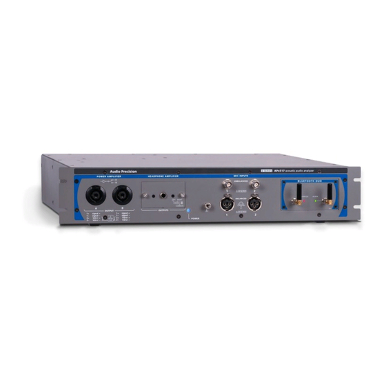
APx500 v6.0.1 or higher measurement software October 28, 2020 NP0020.00045 rev. 000 This illustration shows an APx517 B Series with the 1/4 inch headphone jack. These specifications cover the analog input, power amplifier output, headphone amplifier out- put, and General and Environmental specifications of the APx517 B Series analyzer. - Page 38 ±0.20 dB Typically < 0.010 dB 20 kHz to 50 kHz ±0.80 dB Residual THD+N {notes 1,2} Fs = 20 Hz-20 kHz ≤ (-80 dB + 30 μV), 20 Hz to 20 kHz BW APx517 B Series Acoustic Analyzer: Specifications...
- Page 39 DFD & CCIF Difference Frequency (Fdiff) 80 Hz to 2.00 kHz Fdiff = |F2 - F1| Fmean must be ≥ 6*Fdiff Mean Frequency (Fmean) 250 Hz to 60.00 kHz Fmean = (F1 + F2)/2 APx517 B Series Acoustic Analyzer: Specifications...
- Page 40 ≤ 2% for resistive load 2 Ω to 4 Ω, 20 Hz to 20 kHz Vdriver Maximum Input Voltage Balanced 40 Vpk (80 Vpp), differentially 6.0 Apk 35 W into 2 Ω Maximum Output Current APx517 B Series Acoustic Analyzer: Specifications...
- Page 41 ≤ (-84 dB + 15 μV), 20 Hz to 20 kHz 800 Ω load Fs = 20 Hz-20 ≤ (-90 dB + 15 μV), 20 Hz to 20 kHz Non-Harmonic Content Typically < -125 dB, 20 Hz to 20 kHz APx517 B Series Acoustic Analyzer: Specifications...
- Page 42 240 Hz to 60.00 kHz Mix Ratio (LF:HF) 10:1, 4:1, or 1:1 Amplitude Range 0 to 25.456 Vpp Amplitude Accuracy ±0.08 dB [±0.70%] Residual IMD {notes 1,2,3} ≤ 0.032% [-70 dB], 4:1 mix ratio APx517 B Series Acoustic Analyzer: Specifications...
- Page 43 Ω, 20 Hz to 20 kHz ≤ 1% for resistive load 350 Ω to 800 Ω, 20 Hz to 6 kHz ≤ 3 % for resistive loads 350 Ω to 800 Ω, 6 kHz to 20 kHz APx517 B Series Acoustic Analyzer: Specifications...
- Page 44 Number of Channels 354 mVpk to 35.36 Vpk (250 mVrms Maximum ac signal is ≈25 Vac rms Input Ranges to 25 Vrms), 10 dB steps unbal, 25 Vac rms bal, in the 25V range APx517 B Series Acoustic Analyzer: Specifications...
- Page 45 Fundamental Range 5 Hz to 80.1 kHz Measurement Range 0 to 100% Accuracy ±0.5 dB Residual THD+N {notes 1,2} 20 Hz-20 kHz fundamentals ≤ (-98 dB + 1.9 μV), 20 Hz to 20 kHz APx517 B Series Acoustic Analyzer: Specifications...
- Page 46 CCITT, C-message, 50 μs or 75 μs high-pass and low-pass filters de-emph (with and without A-wt), or None Arbitrary 30-pole input filter The EQ operates on any selected Mic Input Equalization Inputs input channels. APx517 B Series Acoustic Analyzer: Specifications...
- Page 47 0 dB reference giving readings 2x higher than DFD Measurement Range 0 to 20% Accuracy ±0.5 dB Residual IMD {notes 1,2,3} SMPTE & MOD ≤ -90 dB [0.0032%], 4:1 mix ratio ≤ -100 dB [0.0010%] APx517 B Series Acoustic Analyzer: Specifications...
- Page 48 ±40 Vdc maximum in 25 V range. Accuracy 250 mV and 800 mV ranges ±(0.7% reading + 1 mV) 2.5 V-8 V ranges ±(0.7% reading + 0.1% range) Normal Mode Rejection Typically > 90 dB, 20 Hz to 20 kHz APx517 B Series Acoustic Analyzer: Specifications...
- Page 49 FCC 15.109(g):2020 Class B ICES-003:2016 updated 2017 and 2019 Class B FOR BT EQUIPPED 2014/53/EU (RED) EN 300 328 V2.2.2:2019-07 EN 301 489-17 V3.1.1:2017 FCC 15.247:2020 FCC 15.207:2020 RSS-247:2017 LP0002:2020 CNS 13438:2006 (Complete) Class B APx517 B Series Acoustic Analyzer: Specifications...
- Page 50 Equipment Having Testing or Measuring Circuits EN 61010-2-030:2010/COR1:2011, Particular Requirements for Equip- ment Having Testing or Measuring Circuits Dimensions Width 482.6 mm [19.00 inches] Height 87.4 mm [3.44 inches] Depth 455.7 mm [17.94 inches) APx517 B Series Acoustic Analyzer: Specifications...
- Page 51 Valid for the balanced input configuration with DC coupling only. With AC coupling, specified performance is invalid below 50 Hz. Maximum low-pass filter frequency is limited by Mic Inputs' bandwidth setting. Filter response is relative to "no filter" selection; overall system performance will also include analog flatness imperfections. APx517 B Series Acoustic Analyzer: Specifications...
- Page 52 APx517 B Series Acoustic Analyzer: Specifications...
-
Page 53: Dio Digital Input/Output Module Specifications
December, 2018 This illustration shows an APx DIO module, model 240. These specifications cover the digital input and output functions of the Audio Precision DIO. The DIO is available as a stand-alone module (models 240). The APx DIO provides balanced digital input and output compatible with AES3, AES/EBU and IEC60958-4, on XLR connectors;... - Page 54 Sine, sine split frequency, sine split 8–24 bit word width, triangular PDF Waveforms phase, sine+DC offset, continuously dither swept-sine, square-wave, noise, IMD signals, multi-tone, constant value, walking ones/zeros, bittest random, wave file playback APx DIO Module for B Series: Specifications...
- Page 55 2.5 kHz to (0.499 • SR – F / 2) or = |F2-F1|; diff diff must be 6 • Fdiff 60 kHz, whichever is lower mean Typically < –150 dBFS Residual IMD APx DIO Module for B Series: Specifications...
- Page 56 5 Hz to 0.49 • SR or 50 kHz, Tuning can be set to track measured fre- whichever is lower quency, generator setting or fixed Measurement Range 0 to 100% Accuracy ±0.5 dB Typically < –140 dBFS Residual THD+N APx DIO Module for B Series: Specifications...
- Page 57 Any two-tone combination with mean = (F1 + F2)/2 mean frequency of 250 kHz–60 kHz and a = |F2 - F1| diff difference frequency of 80 Hz–2.0 kHz must be 6 • F mean diff APx DIO Module for B Series: Specifications...
- Page 58 2 Digital generator word width must be set to 24 bits for specified performance; shorter word widths may degrade per- formance. 3 Maximum low-pass filter frequency is limited by input sample rate (SR). 4 DSP warping may significantly increase roll-off rate and lower ENBW. APx DIO Module for B Series: Specifications...
-
Page 59: Dsio Digital Serial Input/Output Module Specifications
March, 2020 This illustration shows an APx DSIO module, model 237. These specifications cover the digital serial input and output functions of the Audio Precision DSIO. The DSIO is available as a stand-alone module (model 237). The Digital Serial Input/Output (or DSIO) option provides a flexible chip- or board-level serial input and output interface. - Page 60 4 kS/s–216 kS/s 16 channels 4 kHz–56 MHz Actual clock rate is dependent upon bit Master Clock range clock, word width, and sample rate set- tings. 1.8 V, 2.5 V, 3.3 V Logic voltage levels APx DSIO Module for B Series: Specifications...
- Page 61 2.5 volt setting High level input Minimum 1.4 V Low level input Maximum 1.1 V High level output Minimum 2.2 V Low level output Maximum 0.1 V Absolute range Minimum –0.5 V Maximum 5.5 V APx DSIO Module for B Series: Specifications...
- Page 62 Frame, setup 6 ns referenced to Bit clock Frame, hold 2 ns referenced to Bit clock Data 1–4, setup 6 ns referenced to Bit clock Data 1–4, hold 2 ns referenced to Bit clock APx DSIO Module for B Series: Specifications...
- Page 63 ±0.01% Flatness ±0.01% Spurious products are typically Jitter Spectrum –40 dBc (below jitter signal) or –60 dBUI, whichever is larger. Square Wave and Noise Waveform Jitter Jitter amplitude limited to 40 ns maximum. APx DSIO Module for B Series: Specifications...
- Page 64 Clock 192 kHz. 2 In TDM, channel count can limit the bit clock rate. 3 For Digital Serial (DSIO), the Unit Interval (UI) is defined as 1/fb, where fb is the bitclock rate in hertz. APx DSIO Module for B Series: Specifications...
-
Page 65: Bluetooth Input/Output Module Specifications
APx52x, 555 and 58x B Series audio analyzers NP0020.00044 rev 000 December, 2018 This illustration shows the Bluetooth Duo module, model 241. These specifications cover the digital input and output functions of the Audio Precision Blue- tooth Duo interface. ® Bluetooth is a short-distance (a few meters) control, data, and audio communications wireless technology. - Page 66 SMA x2 Typically 50 Ω RF Input Impedance Typically 50 Ω RF Output Impedance Typically 0 dBm RF Power Typical maximum +8 dBm Typically –81 dBm RF Sensitivity (0.1% BER) APx Bluetooth Duo I/O Module for B Series: Specifications...
-
Page 67: Hdmi+Arc Input/Output Module Specifications
December, 2018 This illustration shows the HDMI+ARC module, model 242. These specifications cover the input and output functions of the Audio Precision HDMI+ARC (High Definition Multimedia Interface plus Audio Return Channel) I/O module. HDMI+ARC is available as a stand-alone module, model 242. - Page 68 The embedded and encoded audio sig- put of a DUT. nal components are recovered for analy- sis. HDMI Type A Hardware Interface 256-byte EEPROM on both Sink and EDID ARC TX / AUX IN connectors. APx HDMI+ARC I/O Module for B Series: Specifications...
- Page 69 Full implementation per IEC60958 Automatically set or manual override, Channel Status Bits hex or plain English. Fully settable Hex. User Bits Validity Flag Set to 0, all channels <1.0 ns typical Residual Jitter APx HDMI+ARC I/O Module for B Series: Specifications...
- Page 70 MOD Upper Frequency (HF) 240 Hz to (0.499 • SR) or 60 kHz, whichever is lower Mix Ratio (LF:HF) 10:1, 4:1 or 1:1 Typically < –140 dBFS Residual IMD APx HDMI+ARC I/O Module for B Series: Specifications...
- Page 71 –3 dB at 4.1 Hz Butterworth (–3 dB) = 10 Hz to 100 kHz, 4-pole Elliptic (–0.01 dB) = 10 Hz to 100 kHz, 5-pole; 0.01 dB pass-band ripple; ≤–60 dB stop-band APx HDMI+ARC I/O Module for B Series: Specifications...
- Page 72 Use “d2+d3” for measurements per IEC-60268. CCIF d2 only “CCIF” is an archaic form of DFD that measures only the d2 product. CCIF uses a different 0 dB reference giving readings 2x higher than DFD. APx HDMI+ARC I/O Module for B Series: Specifications...
- Page 73 Sample rate (SR) must be 27 kHz for specified performance. Jitter analyzer set for 700 Hz highpass response per AES3-1992. Digital generator word width must be set to 24 bits for specified performance; shorter word widths may degrade performance. DSP warping may significantly increase roll-off rate and lower ENBW. APx HDMI+ARC I/O Module for B Series: Specifications...
- Page 74 Characteristic Specifications Supplemental Information APx HDMI+ARC I/O Module for B Series: Specifications...
-
Page 75: Pdm Input/Output Module Specifications
Decimated Rate. The input bitstream can also be analyzed directly (before decimation) in the Signal Analyzer to view out-of-band components. These specifications cover the digital input and output functions of the Audio Precision PDM interface for the current version, model 236. - Page 76 MIL to 0 dBFS (order 4) –0.010 +0.002 MIL to 0 dBFS (order 5) –0.010 +0.001 Ones Density at Full Scale 99.94 MODULATOR: ORDER 4, 64x OSR Overload Point 1 kHz –7.8 dBFS APx PDM I/O Module for B Series: Specifications...
- Page 77 Overload Point 1 kHz –9.8 dBFS @OLP; BW = 0.45 F Total Harm. Dist. + Noise –128 @OLP; BW = 0.45 F Signal-to-Noise Ratio @MIL; F = 48 kHz; per AES17 Dynamic Range APx PDM I/O Module for B Series: Specifications...
- Page 78 DECR = 1, 4, 8, 16, 32, 64, 128, Passband Gain –0.001 +0.001 256, 512 All other DECR –0.005 +0.005 Stopband Frequency Range All DECR except DECR = 1 0.55 DECR/2 Stopband Attenuation All DECR except DECR = 1 APx PDM I/O Module for B Series: Specifications...
- Page 79 LOAD VDD OUTPUT DC Voltage 0.80 3.60 Resolution 0.01 Accuracy ±0.05 Maximum Current VDD MODULATION AC output level All waveforms 0.01 Square/Pulse Frequency Per GSM standard 216.667 Sine Frequency 22000 Frequency Accuracy APx PDM I/O Module for B Series: Specifications...
- Page 80 Clock to out Rise Time Fall Time Output Impedance ohms Maximum Clock Frequency 6.144 Logic Level = 1.5 V Clock to out Rise Time Fall Time Output Impedance ohms Maximum Clock Frequency 12.28 APx PDM I/O Module for B Series: Specifications...
- Page 81 Clock period (master or slave 7813 CLKRX mode) Data hold time, rising edge Data hold time, falling edge Data setup time BITCLK DATA TX CH 1 CH 2 CH 1 CH 2 DATA RX APx PDM I/O Module for B Series: Specifications...
- Page 82 Sine wave jitter, bit clock rates 3.5 UI, from 128kHz to 24.576 MHz. (subject to 1591 ns max jitter limit) Induced Jitter Waveforms Sine, Square, Noise Signals Affected Bit Clk and Data APx PDM I/O Module for B Series: Specifications...
- Page 83 1. System specification including contributions from both generator and analyzer subject to the following condition: Bit Clock ≥ 192 kHz. 2. For PDM, the Unit Interval (UI) is defined as 1/fb, where fb is the bitclock rate in hertz. APx PDM I/O Module for B Series: Specifications...
- Page 84 APx PDM I/O Module for B Series: Specifications...
-
Page 85: Pdm 16 Input Module Specifications
PDM 16 input module specifications with APx500 v5.0.3 or higher measurement software as fitted in APx52x, 555 and 58x B Series audio analyzers NP0020.00046 rev 000 November 2019 This illustration shows the PDM 16 module, model 243, and PDM 16 remote interface pod. - Page 86 These specifications cover the digital input functions of the Audio Precision PDM 16 interface for the current version, model 243. PDM 16 specifications begin on the next page. APx PDM 16 Input Module for B Series: Specifications...
- Page 87 Passband Gain DECR = 32 -0.01 +0.01 Stopband Frequency Range 0.55 DECR/2 Stopband Attenuation DISTORTION, NOISE and DYNAMIC RANGE (when tested with APx PDM Module output) MODULATOR: ORDER 4, 64X OSR APx PDM 16 Input Module for B Series: Specifications...
- Page 88 Dynamic Range @MIL; FS = 48 kHz, per AES17 MODULATOR: ORDER 4, 256X OSR Overload Point 1 kHz -8.0 dBFS Total Harm. Dist. + Noise @OLP; BW = 0.45 FS -130 APx PDM 16 Input Module for B Series: Specifications...
- Page 89 Signal-to-Noise Ratio @OLP; BW = 0.45 FS Dynamic Range @MIL; FS = 48 kHz, per AES17 INPUT CHARACTERISTICS >100 kOhms Impedance < 10 Input Voltage Range Interface Voltage (Logic Level) VINT 3.30 APx PDM 16 Input Module for B Series: Specifications...
- Page 90 1. System specification including contributions from both generator and analyzer subject to the following condition: Bit Clock ≥ 192 kHz. 2. For PDM, the Unit Interval (UI) is defined as 1/fb, where fb is the bitclock rate in hertz. APx PDM 16 Input Module for B Series: Specifications...
- Page 92 Audio Precision, Inc. 5750 SW Arctic Drive Beaverton, Oregon 97005 800-231-7350...
Need help?
Do you have a question about the B Series and is the answer not in the manual?
Questions and answers