Table of Contents
Advertisement
Quick Links
1. INTRODUCTION
The vane pumps use a rotor with sliding blades that push the liquid behind each blade from the inlet opening and move it to
the pumping chamber. When the rotor turns, the liquid is transferred among the vanes to the outlet opening being
discharged, while the pumping chamber is compressed. Each blade applies a positive mechanical thrust to the liquid it has.
The blade contact with the chamber walls is kept by three forces:
The centrifugal force of the rotor rotation.
Thrust rods that act between the opposed pairs of vanes.
The liquid pressure that gets in the slots of the vanes and acts in their top.
Each revolution of a pump displace a constant volume of fluid. The pressure variation has a minimum effect. The losses
and turbulences are reduced at minimum while the high volumetric output is guaranteed.
They are heavy duty pumps, made of cast iron and stainless steel, with single-race grease-lubricated ball bearings and
isolated from the pumping product by mechanical seals with nitrile or Viton joints, according their needs.
All the pumps has built in a safety valve. They are perfectly adapted to the truck service and transport, in general,
tank load and unload, storage of fuel or any other non-corrosive liquid free of particles in suspension.
TECHNICAL DATA
BDP
MODELS
Maximum pump speed ( rpm)
Maximum viscosity¹
Maximum temperature²
Maximum differential pressure
Maximum working pressure
(1) The viscosity shown is in SSU (cP). cP= cSt for a fluid with a density of 1 kg/dm³.
(2) The maximum surface temperature of the pump in potentially explosive atmospheres is 135 ºC.
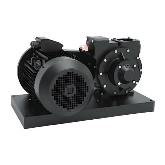
BDP · HIGH FLOW PUMPS
INSTRUCTION MANUAL
1"
1,400
PUMP SIZE
1.5"
2.5"
3"
740
640
640
20,000 (4250)
356 ºF (180 ºC)
125 psi (862 kPa)
175 psi (1207 kPa)
4"
520
P
P
a
a
g
g
e
e
1
1
o
o
f
f
2
2
4
4
Advertisement
Table of Contents

Subscribe to Our Youtube Channel
Related Manuals for Gespasa BDP


Summary of Contents for Gespasa BDP
- Page 1 BDP · HIGH FLOW PUMPS INSTRUCTION MANUAL 1. INTRODUCTION The vane pumps use a rotor with sliding blades that push the liquid behind each blade from the inlet opening and move it to the pumping chamber. When the rotor turns, the liquid is transferred among the vanes to the outlet opening being discharged, while the pumping chamber is compressed.
- Page 2 SAFETY INFORMATION Serious or fatal injuries may be caused if the power supply is not disconnected and cut before undertaking maintenance. Serious injuries to people, damage to property or even the death may be caused by operating the pump without the protections properly installed. ...
-
Page 3: Suction Hose
2. WARNINGS When choosing a pump, first decide its flow (l/min) you required and then the pump series for the specific application. 2 .1. SUCTION HOSE The pump is thought to give its capacity, but according to the load suction there may be restrictions because the suction pipe is too long or its diameter is too small. -
Page 4: Installation
3. INSTALLATION Note: The motorised pumps must be only installed in the systems designed by qualified technical personnel. The system must comply with all the pertinent regulations and codes and must include warning signs for all the implicit dangers. -
Page 5: Coupling Alignment
Please also check the coupling alignment after fixing the pump set and the base to the foundations. 3.4. COUPLING ALIGNMENT The pump must be connected directly to the gear box and or the transmission system through a flexible coupling. The coupling alignment (both angular and parallel) MUST BE KEPT among the pump, the box gear, the motor etc. -
Page 6: Pump Rotation
3.5. PUMP ROTATION To set the pump turn sense: If the pump opening inlet and the safety valve are on the right, with the shaft drive side pointing to the observer, the pump turns to the right, i.e. clockwise ... -
Page 7: Operation
4. OPERATION Serious injuries to people, damage to property or even the death may be caused by operating the pump without the protections properly installed. Injury to people or damage to property may be caused by operating the pump with a closed valve, causing the breaking of the system components. - Page 8 4.4. PUMP SAFETY VALVE NOTE: The internal safety valve of the pump has been designed to protect the pump against an excessive pressure and it must not be used as a control valve of the system pressure. The volatile liquid pumping in adverse suction conditions can cause cavitation.
- Page 9 The pump must be freely exposed to the atmosphere, allowing its own cooling. 4.7. ATEX MARK OF THE EQUIPMENT Equipment description: High flow blade pumps · Series: BDP-300 · BDP-400 · BDP-500 · BDP-600 · BDP-800 Marked: II 2G DT *...
- Page 10 Serial number: The ATEX plate is placed along with the pump identification plate. *All the pumps are classified as Group II category 2. The maximum surface temperature is different for each model, as shown in the below table: TEMPERATURE CLASS PUMP MODEL T4 ( 135 ºC) BAL- 2R...
-
Page 11: Pump Maintenance
5. PUMP MAINTENANCE Note: The maintenance of the pump only must be made by qualified technicians following the correct procedures and warning according to this instruction manual. Electric shocks, burns or even death may be caused if the power supply is not disconnected before starting the pump maintenance. - Page 12 5.2. VANE REPLACING To change the vanes (no. 6) is very easy. In a few seconds the pump is working again. 1. Just disassemble the external head set. 2. Remove the old vanes. 3. Insert the new ones. 4. Reassemble the head again. The routine checks are also easy.
-
Page 13: Pump Troubleshooting
6. PUMP TROUBLESHOOTING DESCRIPTION POSSIBLE CAUSE The pump is not wet Worn banes Closed suction valve Air inlet in the suction pipe The pump does not prime. Blocked filter Blocked or too restrictive suction pipe or valves Blocked pump by the steam Pump speed not enough for the priming Safety valve partially open or worn or with a non-proper seat. - Page 14 7. PUMP ASSEMBLY INSTRUCTIONS Assembly: First fit the rotary mechanical seal no. 39/2 in the pump rotor/shaft no. 5 & 11 respectively. Lubricate the shaft no. 11 of the pump and turn inwards the rotary mechanical seal no. 39/2 until it touches the rotor base no.
- Page 15 Then fit the bearing no. 18 and the blocking washer no. 18/1 & no. 18/2, adjusting them without tightening them so much. The next step is to place upwards this assembly and seated it in the assembly pipe; fit the axial joint no.
- Page 16 Insert the vanes no. 6 in their corresponding slots. The vanes no. 6 must be placed clockwise in the channels and the rounded edge looking outwards the motor. Fit the body no. 1. Tighten the bolts that joint the body no. 1 with the cover no.
- Page 17 Then use two bolts to fix the cover no. 2D to the pump body no.1 without tightening it so much. Then place the blocking washer no. 18/1 along with the blocking nut no. 18/2 and find the correct gap between the parts of the rotor no.
- Page 18 To assembly the bypass start fitting the valve no. 14 in the body nº 1 hole of the pump that is on the suction hole (for a standard assembly). Then insert the spring no. 16 until it is seated in the valve no. 14. ...
- Page 19 Then fit the gasket for the tensor cap no. 8/1. Tighten the tensor cap no. 8 with the fixing bolts and fit the tensor stud no.
- Page 20 Then fit the joint of the cap nut no. 17/1. Finally, thread the cap nut no. 17 in the tensor stud.
- Page 21 removing the blocking nut (no. 18/1) and the blocking washer (no. 18/2). Then tap the shaft with a plastic mallet, removing the rotor (no.5) and the cover (no. 2D). Remove this cover, the bearing (no.18) and the fixed part of the mechanical bearing (no. 39/2) by turning it with the hand towards you.
-
Page 22: Warranty
8. WARRANTY 1. All the products manufactured by TOT COMERCIAL SA have a WARRANTY of 12 (twelve) months from their purchase, against any manufacturing defect. 2. TOT COMERCIAL SA guarantees, in the warranty period, the change/the devolution of the defective part or product. - Page 23 Partida Horta d'Amunt s/n - Apartado Correos nº 149 25600 BALAGUER (Lleida) SPAIN DECLARES: Under its own responsibility that the following supplied product: HIGH FLOW PUMP Mark: GESPASA Model: is in accordance with the following legislative and/or normative documents: DIRECTIVES No. and date...
Need help?
Do you have a question about the BDP and is the answer not in the manual?
Questions and answers