
Related Manuals for BTEK T419S


Summary of Contents for BTEK T419S
- Page 1 CONFIDENTIAL T419S Indicator Service Manual original instructions AMERICAS AWT35-501788 Issue AC...
- Page 2 © 2019 B-TEK. All rights reserved. BTEK_T419S_s_en_501788‘.book...
-
Page 3: Table Of Contents
BSQ ..........................25 DigJbox ..........................25 Chapter 6 ADMIN Menu ........................... 26 Calibrate ........................... 28 Zero procedure ......................28 Span procedure ......................29 Linearity (Linear) procedure ..................30 Build.Up procedure ....................30 Input procedure ......................30 T419S Indicator Service Manual... - Page 4 About Command Response ..................61 Scale Information Command Response ..............62 Extended SMA Commands ..................63 ENQ & B-Cast commands ....................65 NCI commands ........................ 66 PLC Configuration information ..................67 ModBus/TCP ......................67 Ethernet/IP Implicit Messaging: ................. 68 T419S Indicator Service Manual...
- Page 5 Additional token tables ....................109 Network tokens ......................110 ASCII characters (UNI-code UTF-8) ................115 Control codes ......................... 116 Chapter 12 T419S Menus ........................117 Chapter 13 Technical illustrations ...................... 119 Exploded drawing ......................119 Parts Kits ........................120 Panel mount exploded drawing ..................121 Panel Mount kits ............................
- Page 6 System block diagram ....................123 B-TEK Remote Inputs and Outputs, Opto-22 Module Application Notes ...... 124 I/O interfaces ......................124 Inputs ........................124 Outputs ........................125 Diagnostics ........................126 External Opto I/O Cards ....................129 Index ............................... 131 T419S Indicator Service Manual...
-
Page 7: Manual Revision History
Manual revision history Current Date Created Details of Changes Issue October 2018 New manual October 2018 Added info on the ZB210 digital junction box. January 2019 Small corrections. T419S Indicator Service Manual... -
Page 8: Chapter 1 General Information And Warnings
Cautions give information about procedures that, if not observed, could result in damage to equipment or corruption to and loss of data. NOTE: This is a Note symbol. Notes give additional and important information, hints and tips that help you to use your product. T419S Indicator Service Manual... -
Page 9: Installation
On the aluminum and panel mount models the shield wires should be connected to the SHLD connection on the corresponding terminal block connectors. T419S Indicator Service Manual... -
Page 10: Safe Handling Of Equipment With Batteries
Installations within Europe must use a socket which provides a minimum of IP56 protection to the plug / cable assembly. Care must be taken to make sure that the degree of protection provided by the socket is suitable for the environment. T419S Indicator Service Manual... -
Page 11: Panel Mount Scale Interface Cable Installation
Installation 1.2.5 Panel mount scale interface cable installation The T419S panel mount assembly includes the AWT25-501388 ferrite. Installing the ferrite on the scale interface cable on the panel mount models assists with eliminating potential noise captured by the scale interface cable. -
Page 12: Routine Maintenance
To avoid the risk of RSI (Repetitive Strain Injury), place the machine on a surface which is ergonomically satisfactory to the user. Take frequent breaks during prolonged usage. 1.6 Sharp objects Do not use sharp objects such as screwdrivers to operate the keys. T419S Indicator Service Manual... -
Page 13: Fcc And Emc Declarations Of Compliance
Classe A prescrites dans le Règlement sur le brouillage radioélectrique edicté par le ministère des Communications du Canada. European Countries WARNING: This is a Class A product. In a domestic environment, this product may cause radio interference in which the user may be required to take adequate measures. T419S Indicator Service Manual... -
Page 14: Chapter 2 Introduction
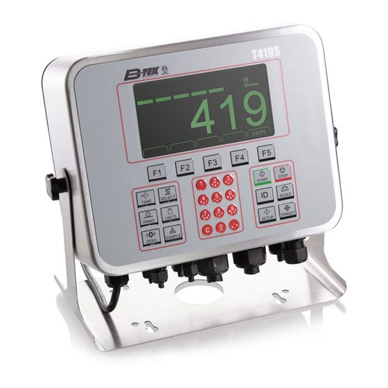
Introduction The T419S indicator is a powerful, programmable indicator. It comes in both a desk top version and as a panel mount. The T419S comes with an accumulation weighing application. This manual will explain the following: the Setup, Diagnostics, User and Audit menus... -
Page 15: Front Panel Keys
Front Panel Keys 2.1 Front Panel Keys The key functions for the T419S are listed below. Press the TARE key to perform a pushbutton tare function. Acts as an up arrow key for menu navigation. TAR E Press the SELECT key to toggle between the active display values. -
Page 16: Display
C key (or PRINT key) to clear the current value from the display. To enter a decimal point, a comma or minus sign, repeatedly press the decimal point key until it appears on the display. The next chapters cover the menus in detail. T419S Indicator Service Manual... -
Page 17: Chapter 3 Introduction To The Menus
Use the Up or Down key to make your choice and press the ENTER key to accept. The indicator will reboot and return to the startup screen with the new changes active. T419S Indicator Service Manual... -
Page 18: Chapter 4 User Level Menu
• Print Key in Displays • Style • Style Site ID Seal • Port 1 number status • Port 2 • Port 3 • USB Archive menu item appears only if enabled in the ADMIN>System menu. T419S Indicator Service Manual... -
Page 19: About Menu
• Bus 1 • Version • Version • Version indicator • Bus 2 • Subnet • dSerial • SW Part • Gateway • Card 1 • Version • MAC • Cur.Ser • Type • Cal.Ser • Version T419S Indicator Service Manual... - Page 20 Version - View the firmware version of the cell that is connected. Cur. Ser - View the serial number of the cell that is connected. Cal. Ser - View the serial number of the cell that WAS connected at the time of calibration. T419S Indicator Service Manual...
-
Page 21: Audit Menu
Under Port 3 choose to print to a column or ticket printer. Printing to USB requires that a USB flash drive is connected to the indicator host USB. Printing to USB will create a folder on the flash drive and a comma separated file with the data. T419S Indicator Service Manual... -
Page 22: Chapter 5 Diagnostics Menu
Clear the zero offset to return the indicator to calibration zero. Choose Yes or No. This can restore the original calibration zero point if the ENTER key is accidentally pressed when a tank or vessel contains product that cannot be emptied. T419S Indicator Service Manual... -
Page 23: Display
In 000 is displayed, if no inputs are jumpered. To test input 1, jumper pins 1 and 2 of the I/O connector on the indicator … The first digit becomes 1 until the jumper is removed. T419S Indicator Service Manual... -
Page 24: Outputs
Use this to test the various installed option cards. Bus x Refers to Bus 1 or Bus 2, where the option card is attached. Card x Refers to the position of the S1 switches on the option card. See Switch S1 settings on page T419S Indicator Service Manual... -
Page 25: Logs
ZB210 refer to the ZB210 Installation/Service manual, PN AWT35- 501806. The T301 item is not available in the US market. This completes the Diag menu. To exit the menu, see Exiting a menu on page T419S Indicator Service Manual... -
Page 26: Chapter 6 Admin Menu
• Type • Parity • Bind • Type • Beeper • Out • DigJBox • Roc • S-Bits • Config • Num Scl • DigJbox • C-trol • Traffic • None Figure 6.1 ADMIN menu map T419S Indicator Service Manual... - Page 27 The top level of the Setup menu is displayed. Follow the normal navigation rules to move through the items in this menu. Each item is explained below. See Figure 6.3. Setup Calib Scale System Ports Figure 6.3 Setup menu top level T419S Indicator Service Manual...
-
Page 28: Calibrate
This is an alternate zeroing procedure. Use this if certified • Temp test weights placed on the scale display a slightly inaccurate • Last value. See LAST procedure on page CAL.ZERO procedure Highlight Cal.Zero and press ENTER … The CALIBRATE window appears. T419S Indicator Service Manual... -
Page 29: Span Procedure
Place the test weights equal to the calibration weight value on the scale and press ENTER … Busy is briefly displayed then the CALIBRATE screen with the span weight displayed. Press ENTER to accept the span … The screen returns to the home calibration screen. T419S Indicator Service Manual... -
Page 30: Linearity (Linear) Procedure
Use this to enter a span using A to D counts. Use this to enter a span using a mV/V value. The Span value is the differential value of the actual Calibration Zero and Span count (or mV/V) values. T419S Indicator Service Manual... -
Page 31: Gravity Procedure
See Calibration report on page 89 to view a representation of the printed report. This completes the Calib menu. To exit the menu, see Exiting a menu on page T419S Indicator Service Manual... -
Page 32: Digjbox Procedure
MUST enter 1 for a value. Leaving it at 0 disables section weight adjustment. As long as you use the same weight the system will adjust the sections correctly. Remember, a minimum of 10% scale capacity is recommended. T419S Indicator Service Manual... - Page 33 When you find the sensor, either press mV/V to key in a new mV/V output for the sensor, or press Span to key in a new nominal span rating. You will be prompted to key in the new sensors: Capacity T419S Indicator Service Manual...
-
Page 34: Scale Menu
• Type - See Type on page 38 • Roc - See Roc on page 40 • DigJbox - See DigJbox on page 40 • Traffic - See Traffic on page 40 Figure 6.6 Scale menu T419S Indicator Service Manual... -
Page 35: Capacty
‘motion stable’ condition after the ZERO, TARE or PRINT button is pressed. If the intended operation cannot be completed before the timeout, Cant is displayed and the key request is ignored. T419S Indicator Service Manual... -
Page 36: Azt
ENTER and observe the Center of Zero annunciator. If it is on all the time your scale is stable. If the Center of Zero light blinks, more filtering is required. Go to step 3. T419S Indicator Service Manual... -
Page 37: Ranges
This stands for overload. Once you’ve picked the basis for an over capacity condition, use this item to set the value that triggers the overload condition. U-Load This stands for underload. Use this item to set the value that triggers the underload condition. T419S Indicator Service Manual... -
Page 38: Range
Select the mode from these choices: Disable Pick this to disable the selected scale. This is the default setting for Scale 2. Onbrd Pick this if you are using the onboard analog scale. This is the default setting for Scale 1. T419S Indicator Service Manual... - Page 39 If you choose Protcl, you must choose a binding with a protocol selection. There are 20 available protocols and the protocol number selected must be matched with a properly configured protocol shown in Protcl on page T419S Indicator Service Manual...
-
Page 40: Roc
Trigger Enter the percentage of capacity the weight must reach to trigger the traffic counter. Rearm Enter the percentage of capacity the weight must fall below in order to rearm the traffic counter. T419S Indicator Service Manual... -
Page 41: System Menu
CAUTION: Be sure you follow all local weights and measures regulations. To reset the default settings affected by the Site selection, choose an alternate Site selection and press ENTER, then re-select the original Site selection. T419S Indicator Service Manual... -
Page 42: Display
Choose the center-of-zero window size to be 0.25 or 0.50 division. If the weight is within this window, the zero annunciator on the display will be lit. Tot-Scl Use this to enable display of the total of both scale weights if two scales are installed and enabled. T419S Indicator Service Manual... -
Page 43: Buttons
GTotMin Activate this to see the gross total - current gross value. NTotPls Activate this to see the net total + current net value. NTotMin Activate this to see the net total - current net value. T419S Indicator Service Manual... - Page 44 Per Acc Activate this to see the percent accuracy value. The percent accuracy parameter represents the minimum accuracy achieved during the last sample routine. Only one percent accuracy parameter is maintained for all enabled scales. T419S Indicator Service Manual...
-
Page 45: Tare
9 - Printed reports (page 89) Choices are Port 1, Port 2, Port 3 and USB (text file). If USB is selected, a USB flash drive must be installed to create the text file of the indicator configuration. T419S Indicator Service Manual... -
Page 46: Archive
Choices under this are No and Yes. Choose Yes to start the update process. Choose No to not do an update. No is the default. If you choose No, no update occurs and Manual is displayed. If you choose Yes, the indicator will update and reboot. T419S Indicator Service Manual... -
Page 47: Password
Use this to key in the number of scales attached to the scale (4 max). To access settings for a scale use the SCALE key to display the proper scale number. Default is 1. This completes the System menu. T419S Indicator Service Manual... -
Page 48: Ports Menu
Port 1 and Port 3 has both Hard and Soft. Port 2 does not have hardware handshaking. Hardware flow control on Port 1 is only available if C-Trol is set to Hard. When this is selected and Jumper P15 is in position 1, Port 2 is disabled. T419S Indicator Service Manual... -
Page 49: Enet
If DHCP is enabled On, the above settings for the IP, Subnet and Gateway are set by the network server. In applications where the indicator Ethernet port is connected directly to a PC, laptop, printer or other non-DHCP device, you must set DHCP to Off. T419S Indicator Service Manual... - Page 50 Key a port number from 1 to 65535. LcPrt x This stands for Local Port. This is the local port that the remote IP will send messages to. Key in a port number from 1 to 65535. T419S Indicator Service Manual...
-
Page 51: Protcl
None Choose this to disable the selected protocol. Print Choose this when you want to press the PRINT key or when using Autoprint to send the data through the selected binding (Port) using the associated attributes. T419S Indicator Service Manual... - Page 52 Application dependent, used for data exchange port selection. Use to configure an input device type, i.e. bar code scanner, RFID reader, etc., for serial, ethernet or USB interface. ZB210 Choose this when using a ZB210 digital junction box. T419S Indicator Service Manual...
-
Page 53: Edit
In the Broadcast and Enquire Protocols this determines which scale the received commands refer to. 6.4.4 P.F. Edit This stands for print format editor. Please refer to the section Print formatting on page for the procedures to edit or create print formats. T419S Indicator Service Manual... -
Page 54: Plc
Then you will select the data type and then the network token you want assigned to that memory register. In 1-32 These are the 32 inbound data configuration memory registers. For each there are three choices: Type, Value and Scale. See the descriptions below: T419S Indicator Service Manual... -
Page 55: Printer
Prtr 1 You can choose to set up this printer or Prtr 2. The setup procedure is the same. T419S Indicator Service Manual... -
Page 56: File
Use this to configure the file convention. Choices are: Constant This will create a single file that will be appended to as new information is saved. NUMBRD This will create new file appended with a sequential number for each transaction. T419S Indicator Service Manual... -
Page 57: Options
The Ext IO menu item is for the following I/O interface card: External I/O Interface card AC Input 4 relays (120-240VAC) card DC Input 4 relays (4-30VDC) card AC Output 4 relays (20-240VAC) card DC Output 4 relays (3-60VDC) card DeviceNet (DevNet) © Profibus T419S Indicator Service Manual... - Page 58 If DeviceNet card is installed: Config Node 0-63 Baud Select from 125K, 250K or 500K. Rate Select 1, 2, 5, 10, or 20. If Profibus card is installed: Config Node 0-126 Rate Select 1, 2, 5, 10, or 20. T419S Indicator Service Manual...
-
Page 59: Opt232
Use this parameter to configure cards on the option; Expansion RS232 cards. 6.4.10 USB Use this to choose between USB 1 and USB 2 for setting the debounce for the keyboard or scanner input character delay timing. T419S Indicator Service Manual... -
Page 60: Chapter 7 Communication Port Protocols
See “Scale Information Command Response” Information data. (for the current scale) (below) <ESC> The indicator will reboot itself None SMA protocol is maintained by an external organization. For definitive and current details on this protocol go to www.scalemanufacturers.org. T419S Indicator Service Manual... -
Page 61: Standard Scale Response Message
1st response: <xxx> = “SMA” <yyyyy> = compliance level/revision 2nd response: <xxx> = “MFG” <yyyyy> = manufacturer 3rd response: <xxx> = “MOD” <yyyyy> = software part number 4th response: <xxx> = “REV” <yyyyy> = software revision T419S Indicator Service Manual... -
Page 62: Scale Information Command Response
<yyyyy> = “PTMCU” list of supported SMA commands. Level 1 commands are not included in the list. 6th response: <xxx> = “END” <yyyyy> = nothing 7th & more - responses: Subsequent N commands will return a ‘?’ response. Unrecognized Command Response T419S Indicator Service Manual... -
Page 63: Extended Sma Commands
XD, XZ and XS commands, below, only work if the indicator is unsealed. <LF>XC<CR> This will return the audit counters in this format: <LF>Calib:xxx:Config:yyy:<CR> T419S Indicator Service Manual... - Page 64 The indicator will get or return the value of the variable specified by the network token. A valid response is in the form of <LF><value><CR>. <LF>XG<n><CR> This will set the Active Scale. A valid response is in the form of <LF>xg<CR>. T419S Indicator Service Manual...
-
Page 65: Enq & B-Cast Commands
Performs same function as pressing the F5 key *Fires the event for the key. Upper or lower case characters will perform the same function. Only keys found on your model Z-series indicator front panel can respond as defined above. T419S Indicator Service Manual... -
Page 66: Nci Commands
If the PROT > ATTR > ENQ menu value is set to 100, to increase resolution by 100, you may add a 2 or 3 to the command to return a 2 or 3 character status byte. For example: 102 will increase resolution by 100 and return a 2 character status byte. T419S Indicator Service Manual... -
Page 67: Plc Configuration Information
40001 (i.e. Gross, Net, etc.) From PLC Output Read/Write 41025 (i.e. PB-Zero, Print, etc.) 2 Byte Example Indicator Data Type (out) ModBus Register SINT16 40001 SINT16 40002 4 Byte Example Indicator Data Type (out) ModBus Register SINT32 40001 SINT32 40003 T419S Indicator Service Manual... -
Page 68: Ethernet/Ip Implicit Messaging
Refer to the number of items configured for In Configuration at the indicator Configuration INPUT/OPUTPUT SIZE: Is the number of elements (items) configured in the indicator for the data IN and OUT not the number of bytes. T419S Indicator Service Manual... -
Page 69: Ethernet/Ip Explicit Messaging
1-32 (Bound to the instance 1) 1= Block of all elements indicator. See DATA TYPE Element # bound to Instance Instance numbers 2 TABLE, Section 7.5 through 33 are single tags for the data elements 1 through 32 ..T419S Indicator Service Manual... -
Page 70: Chapter 8 Option Cards
8 Option cards Option cards The T419S has several option cards available. Up to 4 cards can be installed in the indicator at the same time. This chapter covers the description and installation of these cards: Analog output card on page 73... - Page 71 8.1. Screws, at the four locations noted by the arrows, hold the board in place. Standoffs are needed between stacked cards. Connector pins on bottom of the card. Stackable cards plug into this connector. Figure 8.1 Option card example T419S Indicator Service Manual...
-
Page 72: Switch S1 Settings
See the illustrations below to set the switches in the proper operating position. Figure 8.2 Card position and switch S1 settings T419S Indicator Service Manual... -
Page 73: Analog Output Card
Figure 8.3 Analog output option card CAUTION: The output will run to the minimum value when a fault occurs and when you enter the Setup menus, so plan accordingly! Function V out Common (GND) I out T419S Indicator Service Manual... -
Page 74: Current Loop/Rs485/Rs422 Card
20ma RCV Return P2 - Jumper On = RCV Sinking P2 - Jumper Off = RCV Sourcing P1 - Jumper On = Terminated P1 - Jumper Off = Unterminated Pin 1 Figure 8.4 Current Loop/RS485/RS422 card T419S Indicator Service Manual... -
Page 75: Usb Device Option Card
PC it creates a Virtual COM Port (VCP). Be sure to make note of the COM port number assigned to the VCP when setting up the serial communication application. Connections to USB Device option card include USB Type B and Mini connectors. T419S Indicator Service Manual... -
Page 76: Devicenettm Option Card
TB1 Pinout DeviceNet Pluggable Connector TB1 Pin No. Signal V- (Bus power GND) CAN_LOW Shield CAN_HI V+ (+24VDC)* *An external power supply will be used to supply V+ power. Typically this supply will be previously installed. T419S Indicator Service Manual... -
Page 77: Software Controlled Baud Rate
S1 switch settings for option cards in card #1 position must be: 1-OFF, 2-OFF, 3-OFF. S1 switch settings for option cards in card #2 position must be: 1-ON, 2-OFF, 3-OFF. Pin 1 Figure 8.7 Profibus option card T419S Indicator Service Manual... -
Page 78: S2 Switch Settings
B-TEK Indicators enclosure. +5V and GND are used for external bus termination if the internal S2 termination resistors are not used. 8.6.1 S2 switch settings: On = Termination resistors Enabled/Present (Default Position) Off = Termination resistors Disabled/Removed T419S Indicator Service Manual... -
Page 79: Wireless Communication Cards
Following is the legacy card used for wireless communication. It is no longer available. Figure 8.8 shows the Wireless Ethernet communication 802.11g card. This provides wireless Ethernet connectivity via the 802.11g protocol. See Switch S1 settings on page 72 Figure 8.8 802.11g wireless communication option card T419S Indicator Service Manual... -
Page 80: Internal 120 Vac Relay Card
Maximum output voltage 120V rms Minimum output voltage 20V rms Maximum output current 1A rms Minimum output current 5mA rms Maximum off-state voltage 400V peak Maximum off-state leakage current 1mA rms Maximum power dissipation 1.6 W T419S Indicator Service Manual... -
Page 81: Installing The Option Card
Option card TB1 pin 7 (OUT3) and the Main Board TB2 pin 7 (OUT3) : SP3 These wires are shown in place in Figure 8.11. The use of Ztools is typically required to configure the AC Relay option card T419S Indicator Service Manual... -
Page 82: Analog Scale Input Option With 5Vdc Excitation
+SEN -SIG +SIG SHLD SENSE Excitation Jumpers 4 wire loadcells requre jumpers to be ON the pins. 6 wire loadcellss require jumpers to be OFF the pins. Figure 8.12 5VDC Excitation Analog Scale Input option card T419S Indicator Service Manual... -
Page 83: Analog Scale Input Option With 10 Vdc Exit. And Stvs
SENSE Excitation Jumpers protection. 4 wire load cells require jumpers to be ON the pins. 6 wire load cells require Pin 1 jumpers to be OFF the pins. Figure 8.13 10VDC Excitation Analog Scale Input option card T419S Indicator Service Manual... -
Page 84: External I/O Interface Card
16 position I/O board (J1) AWT05-508727 TB2 is for connecting to an external SSCU8 board (TB35) AWT05-508726. Pin 1 The use of Ztools is required to configure the External I/O option card. T419S Indicator Service Manual... -
Page 85: Ac Input, 4 Inputs (120-240Vac) Card
CAUTION: For safety reasons the AC Input option card can only be used in the primary earthed stainless steel enclosure. 120-240 VAC <10mA AC Plug Neutral Ground AWT25-501903 PCBA The use of Ztools is required to configure the AC Input option card. T419S Indicator Service Manual... -
Page 86: Dc Input, 4 Inputs(4-30Vdc) Card
DC Power Source 4-30 VDC Ground Indicator +5VDC to 0 Logic Signal Low signal activated Digital PLC/HMI device digital I/O Input Common ground between devices The use of Ztools is required to configure the DC Input option card. T419S Indicator Service Manual... -
Page 87: Ac Output, 4 Relays (20-240Vac) Card
I = 1 Amp AC Plug M ax Neutral Ground AC Load AWT25-501901 PCBA 20-240 VAC 1 Amp Max Figure 8.15 Wiring examples The use of Ztools is required to configure the AC Output option card. T419S Indicator Service Manual... -
Page 88: Dc Output, 4 Relays (3-60Vdc) Card
Pin 1 = 2 Amps MAX External DC Power Source 3-60 VDC for output control Load AWT25-501894 PCBA Ground Figure 8.16 Wiring example The use of Ztools is required to configure the DC Output option card. T419S Indicator Service Manual... -
Page 89: Chapter 9 Printed Reports
SCALE_1_SPAN_FACTOR Value = 0.00000909 SCALE_1_GRAVITY Value = 9.8043 SCALE_1_ZERO_MV Value = 0.38003510 SCALE_1_SPAN_MV Value = 1.63769878 SCALE_1_ALTITUDE Value = 0.00000000 SCALE_1_LATITUDE Value = 0.00000000 SCALE_1_SPAN_COUNTS Value = 1099040 SCALE_1_CAL_WEIGHT Value = 10.0000000 UNIT SERIAL NUMBER Value = 20120111 T419S Indicator Service Manual... -
Page 90: Audit Report
2017-03-20 10:12:30 SCALE_1_UNIT3 2017-03-20 10:08:17 PROTOCOL_1_TYPE 2017-03-20 10:00:27 PROTOCOL_2_FORMAT_1 2017-03-20 09:14:45 SCALE_1_UNIT4 2017-03-20 09:10:35 SCALE_1_UNIT3 2017-03-20 09:10:30 SCALE_1_UNIT2 2017-03-20 09:10:27 SCALE_1_SPAN_FACTOR 0.00003265 0.00003707 2017-03-20 09:09:43 SCALE_1_ZERO_COUNTS 394685 -651448 2017-03-20 09:09:27 PROTOCOL_2_BIND 2017-03-20 09:09:14 PROTOCOL_2_TYPE 2017-03-20 09:09:12 T419S Indicator Service Manual... -
Page 91: Chapter 10 Print Formatting
Increments the Decrements the Exits to Index Deletes the Adds a zero digit Momentary Key Press ESC/Abort value by 1 value by 1 mode right digit to the right Delete the Long Key Press entire entry T419S Indicator Service Manual... -
Page 92: Editing An Existing Print String
Number of characters to insert Decimal value to enter To center the company name on a printed ticket, you must add spaces in front of the company name. This will add to the total count of characters to insert. T419S Indicator Service Manual... -
Page 93: Inserting Characters
The number entry screen is displayed again. Enter the value for the next letter in the company name and press ENTER. Repeat steps until the last character is entered. In this example that would be 13, 10 for the line feed. T419S Indicator Service Manual... -
Page 94: Deleting Characters
The list of print formats is displayed. Highlight PrnFt1 and press ENTER … The first character in the print format will be displayed: 1 , 0 3 2 Press Down to Edit, Enter to Save Arrows Scroll Left/Right T419S Indicator Service Manual... - Page 95 At any time during a string edit you can press SCALE key to abort and exit the print format editor without affecting the existing print string. This allows for an ESCAPE if you think you may have made an error during the editing process. T419S Indicator Service Manual...
-
Page 96: Inserting Tokens, Etc
1 , T 2 0 0 Press Down to Edit, Enter to Save Arrows Scroll Left/Right The value 1 in the above screen will be whatever index value you started from. T419S Indicator Service Manual... - Page 97 The value of the number in this next location identifies what function of the token is being used. Decimal 1 = 49 is the actual Gross weight value. Decimal 2 = 50 is the token name, “Gross”, applied to that token T419S Indicator Service Manual...
-
Page 98: Other Scale Tokens
[ = t501 indicates the start of an optional parameter 68 = D for decimal point parameter 50 = 2 for hide decimal point ] = t502 indicates the end of the optional parameter T419S Indicator Service Manual... -
Page 99: Transmitting Leading Zeros
49 = 1 for use leading zeros ] = t502 indicates the end of the optional parameter For more examples of editing formats consult Print tokens, parameters and default print formats on page 101. T419S Indicator Service Manual... -
Page 100: Print Format Errors
Aspect data invalid, codepoint is NOT 1, 2 or 3 Invalid UTF8 string Left parameter bracket not found Right parameter bracket not found Dot separator not found Token tag string is invalid UTF8 codepoint to large Token to large Error within optional parameter T419S Indicator Service Manual... -
Page 101: Chapter 11 Print Tokens, Parameters And Default Print Formats
TONS you will need to use the WIDTH syntax as follows to have all 3 letters printed to spell TON { T.UNIT.1[W3]} DEFAULTS: Pounds = lb Kilograms = kg Grams Ounces = oz Pounds/Ounces = lb-oz Custom = (first 2 letters) T419S Indicator Service Manual... -
Page 102: Firmware Tokens
0 = Current Scale LSTSTBL Last Stable Weight Last Stable Weight Scale 1 = Scale 1 2 = Scale 2 Percent Percent Target Weight Target GWTPC Gross Total + Current Gross Weight Gross Total + Current T419S Indicator Service Manual... - Page 103 Gross Total All Scales Totals Gross Total All Scales NATAS Net Total All Scales Totals Net Total All Scales TATAS Tare Total All Scales Totals Tare Total All Scales CATAS Count Total All Scales Totals Count Total All Scales T419S Indicator Service Manual...
- Page 104 1 = None 2 = Comma (,) 3 = Period or Decimal Point (.) 4 = Backslash (\) Separator 5 = Space ( ) 6 = Forward Slash (/) 7 = Colon (:) 8 = Dash (-) (default) T419S Indicator Service Manual...
- Page 105 60 = Start Inverse IRCC 8 61 = Start Sum 16 (W/O Twos) 62 = BCC Note: Syntax for CON only: Lower case [i] increments the number Lower case [d] decrements the number Upper case [R] resets the number to zero T419S Indicator Service Manual...
- Page 106 Combinations of these errors can also occur. (e.g., “3 = Range error (2) plus Motion (1)) NAME Indicator Scale Name Scale Name 32 characters max entered in Ztools under SYSTEM TAB Indicator Scale Location Scale Location T419S Indicator Service Manual...
- Page 107 A6 = 0.001 A18 = 10 A7 = 0.002 A19 = 20 A8 = 0.005 A20 = 50 A9 = 0.01 A21 = 100 A10 = 0.02 A22 = 200 A11 = 0.05 A23 = 500 T419S Indicator Service Manual...
-
Page 108: Application Tokens
11.3 Application Tokens Application tokens are defined by the application author at time of application development. PRINT tokens are numbers 1 to 250: Corresponding NETWORK tokens are numbers 1001 to 1250: T419S Indicator Service Manual... -
Page 109: Additional Token Tables
Bit 7 1 = Byte follows 1 = Byte follows Always 0 0 = Last Byte 0 = Last Byte Example: Stable and valid gross weight in lb unit of measure would return "822" Parity Parity Parity T419S Indicator Service Manual... -
Page 110: Network Tokens
Gross Total Plus Current Gross Total Minus Current Net Total Plus Current Net Total Minus Current Count Total Plus Current Count Total Minus Current Gross Average Net Average Count Average Net Max Net Min Freefall 1 T419S Indicator Service Manual... - Page 111 BYTE #1: Bit 0 = Any Fault Indicator Healthy Status (2-Byte) Bit 1 = ADC Error Bit 2, 3, 4 = N/A Bit 5 = Overload Condition Bit 6 = Underload Condition Bit 7 = N/A T419S Indicator Service Manual...
- Page 112 This will give you input setpoints 9-16 FBUS_TOKEN_INPUTS_29 - Mapped as UINT16 (2-bytes or 1-word) FBUS_TOKEN_INPUTS_30 o This will give you input setpoints 9-24 FBUS_TOKEN_INPUTS_31 - Mapped as UINT32 (4-bytes or 2-word) o This will give you input setpoints 9-40 FBUS_TOKEN_INPUTS_32 T419S Indicator Service Manual...
- Page 113 XOR the mapped register with a "1" to Remote PB Accumulate Key toggle the register every time the XOR is executed. Remote PB Units Key 1001- Application defined 1250 2000 Setpoints 3000 WTBasic Events T419S Indicator Service Manual...
- Page 114 4000 WTBasic Fmt Print 5000 WTBasic Store 8000 PDIO A 9000 PDIO B A000 PDIO C * the “Low Weight Value” and “High Weight Value” only apply when the Output mode selection is Act-In or Act-Out T419S Indicator Service Manual...
-
Page 115: Ascii Characters (Uni-Code Utf-8)
0127 0165 0210 Ò 0255 ÿ & & 0166 ¦ 0211 Ó § 0167 0212 Ô ¨ 0168 0213 Õ © 0169 0214 Ö ª 0170 0215 × « 0171 0216 Ø ¬ Ù 0172 0217 T419S Indicator Service Manual... -
Page 116: Control Codes
#DC2 Device Control 3 #DC3 Device Control 4 #DC4 Negative Acknowledge #NAK Synchronous Idle #SYN End of Block #ETB Cancel #CAN End of Medium Substitute #SUB Escape #ESC File Separator Group Separator Record Separator Unit Separator T419S Indicator Service Manual... -
Page 117: Chapter 12 T419S Menus
• Z-Lock • In • Print • Type • Bind • Parity • Type • Beeper • Out • DigJBox • Roc • S-Bits • Config • Num Scl • DigJbox • C-trol • Traffic • None T419S Indicator Service Manual... - Page 118 T419S Indicator Service Manual...
-
Page 119: Chapter 13 Technical Illustrations
LABEL, WHT POLY TAMPER 4x3 PLATE, BACK WELDMENT, MODEL T419S GASKET, UNIVERSAL MODEL T419S SCREW, MACH PH M3x0.5x6mm SST WIRE, GROUND T419S PWR SUP TO CHS WASHER,PLASTIC, 4.0mm POWER SUPPLY, 100-240VAC 65W 24V NUT,M4 W/EXT LOCK WASHER SST CABLE ASSY, T419S POWER SUPPLY... -
Page 120: Parts Kits
LCD Display 320X160 ISTN NEG IMAGE LOSKID 7/16 HEX, 1/16" Thick w/9672 Keypad Overlay Stand, Enclosure T419S 65W Power Supply Kit, AWT05-508855 Display/Keypad Interface PCB LG Kit, AWT05-508957 T419S Overlay and Enclosure Kit, AWT05-509308 Dome Hex Nut Kit, AWT05-508866 Description Qty. Description Qty. -
Page 121: Panel Mount Exploded Drawing
Description QTY. COVER, REAR-PANEL MOUNT DECAL, T419S REAR PLATE, PNL MNT AWT05-509309 PLATE, COVER, PCB, PANEL MOUNT KIT, ENCL & OVERLAY, T419S PANEL MOUNT SCREW, MACH PH M3X0.5 6MML SST Item No. Description QTY. BACKER PLATE/COVER WELDMENT OVERLAY KEYPAD MODEL T419S... -
Page 122: Panel Mount Assembly
TORQUE VALUE FOR THE TENSION BLOCK SCREWS IS 4-5 IN/LBS EXISTING ENCLOSURE DOOR TENSION PLATE PANEL MOUNT GASKET 10.56 [268 mm] 8.31 [211 mm] EXPLODED BACK VIEW ASSEMBLY EXPLODED FRONT VIEW ASSEMBLY FRONT PANEL CUTOUT DIMENSIONS T419S Indicator Service Manual... -
Page 123: System Block Diagram
Description Description -EXC +EXC Input 1 -SEN Input 2 RTS / TX2 RTS3 +SEN Input 3 -SIG Digital Out 1 CTS / RX2 CTS3 +SIG Digital Out 2 5VDC 5VDC SHIELD Digital Out 3 Relay Voltage T419S Indicator Service Manual... -
Page 124: B-Tek Remote Inputs And Outputs, Opto-22 Module Application Notes
Digital logic inputs change state based on a secondary or remote interface (such as a PLC or HMI, human-machine interface). Indicator Mechanical Switch Input Indicator +5VDC to 0 Logic Signal Low signal activated Digital PLC/HMI device digital I/O Input Common ground between devices Figure 13.1 Typical input wiring T419S Indicator Service Manual... -
Page 125: Outputs
Transistor outputs usually switch low voltages and they are limited in voltage and current so you must not exceed their values. There may be a diode for back EMF protection (CR8 in the circuit shown in Figure 13.1) available. It is also possible that the 0 volts line is not isolated. Transistor outputs would have difficulty operating in a circuit where they are expected to switch positive voltages. T419S Indicator Service Manual... -
Page 126: Diagnostics
ALWAYS TRY AND INSTALL A SYSTEM THAT IS FAILSAFE. THIS MEANS THAT IF THE INDICATOR IS SWITCHED OFF, FOR ANY REASON, THE STATE OF THE OUTPUTS WILL BE IN A POSITION TO PREVENT ANY UNWANTED MOTION. T419S Indicator Service Manual... - Page 127 (INTERNALLY LIMITED TO 14mA). 1 2 3 4 5 6 7 8 INPUTS WORK WITH EITHER A DRY CONTACT SWITCH (SW1, SW2) OR A 0 TO +5VDC DIGITAL INPUT (DI3). T YPICAL REM OT E INPUT T419S Indicator Service Manual...
- Page 128 EXTERNAL DC POWER SUPPLY +VDC EXTERNAL DC POWER SUPPLY +VDC -VDC/GND LOAD LOAD -VDC/GND EXTERNAL AC POWER SUPPLY EXTERNAL AC POWER SUPPLY GROUND TO STUD NEUTRAL ON ZMxxx GROUND LOAD LOAD ENCLOSURE TO STUD NEUTRAL ON ZMxxx ENCLOSURE T419S Indicator Service Manual...
-
Page 129: External Opto I/O Cards
13.8 External Opto I/O Cards SSCU-8 Card 16 I/O Card Maximum cable run used between all SSCU8 boards and the indicator should not exceed (2) meters or 78 inches T419S Indicator Service Manual... - Page 130 T419S Indicator Service Manual...
-
Page 131: Index
Diagnostics... 126 Inputs... 23 I/O interfaces... 124 Logs... 24 Inputs... 124 Options... 24 Opto module... 125 Outputs... 24 Outputs... 125 Ports... 23 Relays... 125 Scale... 22 Transistor outputs... 125 DIS token... 109 Application variable token table... 110 T419S Indicator Service Manual... - Page 132 Installation... 9 Passwords... 17 Internal 120 VAC relay card... 80 PLC configuration... 67 Ports menu... 48 Enet... 49 File... 56 Options... 57 Leading zeros P.F. Edit... 53 transmit... 99 PLC... 54 Linearity (Linear) procedure... 30 Printer... 55 T419S Indicator Service Manual...
- Page 133 Seal... 19 WSTAT token... 109 SELECT key... 15 SETUP key... 15 Site ID... 19 SMA Protocol... 60 Level 1 and 2 Commands... 60 ZERO key... 15 Span procedure... 29 Zero procedure... 28 START key... 15 Cal.Zero... 28 T419S Indicator Service Manual...
- Page 134 Last... 28 Temp... 28 T419S Indicator Service Manual...
- Page 136 B-TEK Scale LLC 1510 Metric Ave. SW Canton, OH 44706-3088...
Need help?
Do you have a question about the T419S and is the answer not in the manual?
Questions and answers