SICK PowerProx WTT12L Series Quick Start Manual
Hide thumbs
Also See for PowerProx WTT12L Series:
- Operating instructions manual (168 pages) ,
- Operating instruction (109 pages) ,
- Operating instructions manual (144 pages)
Advertisement
Quick Links
8026849.1D62/13.09.2022
SICK AG
Erwin-Sick-Straße 1
DE-79183 Waldkirch
www.sick.com
PowerProx - WTT12L
LASERKLASSE 1
Laser
1
EN/IEC 60825-1:2014
Maximale Pulsleistung: < 250 mW
Impulsdauer: 4 ns
Wellenlänge: 658 nm
Entspricht 21 CFR 1040.10
und 1040.11 mit Ausnahme von
Abweichungen nach
Laser-Hinweis 56, 8. Mai 2019
UL Environmental Rating: Enclosure Type 1.
Q U I C K S T A R T
en
These instructions are only valid in connection with the 8018110 operating
instructions. You can find the operating instructions at www.sick.com.
de
Diese Anleitung ist ausschließlich in Verbindung mit der Betriebsanleitung
(8018110) gültig. Die Betriebsanleitung finden Sie unter www.sick.com.
it
Le presenti istruzioni sono valide solo in abbinamento alle istruzioni per l'uso
(8018110). Le istruzioni per l'uso sono a disposizione su www.sick.com.
fr
Cette notice n'est valable qu'avec la notice d'instruction (8018110). Elle est
disponible sur le site Internet www.sick.com.
es
Estas instrucciones solo son válidas junto con las instrucciones de uso
(8018110). Puede encontrar las instrucciones de uso en www.sick.com.
zh
本指南仅在结合使用操作指南 (8018110) 的情况下有效。查看操作指南可访
问 www.sick.com 网页。
1
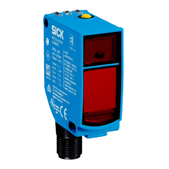
Operating and status indicators
Bedien- und Anzeigeelemente
Elementi di comando e di visualizzazione
Éléments de commande et d'affichage
-xxxx2 / -xxxx4
-xxxx1
1 Single teach-in pushbutton / Einfach-Teach-in-Taste / Pulsante Teach-in sem‐
plice / Touche d'apprentissage simple / Botón de aprendizaje (Teach-in) sim‐
ple / 单示教按键
2 Potentiometer / Potentiometer / Potenziometro /Potentiomètre / Potenció‐
metro / 电位计
3 Potentiometer / LED indicator yellow: status of received light beam / Poten‐
tiometer / LED-Anzeige gelb: Status des empfangenen Lichtstrahls / Potenz‐
iometro/indicatore a LED giallo: stato del raggio luminoso ricevuto / Poten‐
tiomètre/LED d'état jaune : état du faisceau lumineux reçu / Potenció‐
metro/Indicador LED amarillo: estado del haz de luz recibido / 电位计/黄色
状态 LED:接收的光束状态
4 Potentiometer / LED Indicators (green): Power on / Potentiometer / LED-
Anzeigen (grün): Power on /Potenziometro/indicatori LED (verde): Power on /
Potentiomètre/Affichages LED (verts): Power on / Potenciómetro/Indicadores
LED (verde): Power on / 电位计/LED 指示灯(绿色): Power On(电源接通)
8026849.1D62/13.09.2022/de
NO
2006/42/EC
SAFETY
8018110:
Elementos de mando y visualización
操作及显示元件
-xxxx3 / -xxxx7
-xxxx6 / -xxxx8
1
2
3 4
5 Potentiometer / LED indicator yellow: status of received light beam / Poten‐
tiometer / LED-Anzeige gelb: Status des empfangenen Lichtstrahls / Potenz‐
iometro/indicatore a LED giallo: stato del raggio luminoso ricevuto / Poten‐
tiomètre/LED d'état jaune : état du faisceau lumineux reçu / Potenció‐
metro/Indicador LED amarillo: estado del haz de luz recibido / 电位计/黄色
状态 LED:接收的光束状态
2
Mounting
Montage
Montaggio
Montage
en
Mount the sensor using a suitable mounting bracket (see the SICK range of
accessories).
Note the sensor's maximum permissible tightening torque of 0.8 Nm.
Note the preferred direction of the object relative to the sensor [see E].
de
Den Sensor an einen geeigneten Befestigungswinkel montieren (siehe SICK-Zube‐
hör-Programm).
Maximal zulässiges Anzugsdrehmoment des Sensors von 0.8 Nm beachten.
Vorzugsrichtung des Objektes zum Sensor beachten [vgl. E].
it
Montare il sensore su un punto di fissaggio adatto (vedi il programma per acces‐
sori SICK).
Rispettare il momento torcente massimo consentito del sensore di 0.8 Nm.
Rispettare la direzione preferenziale dell'oggetto in relazione al sensore [cfr. E].
fr
Monter le capteur sur une équerre de fixation adaptée (voir la gamme d'accessoi‐
res SICK).
Respecter le couple de serrage maximum autorisé du capteur de 0.8 Nm
Tenir compte de la direction préférentielle de l'objet par rapport au capteur [voir
E].
es
Montar el sensor en una escuadra de fijación adecuada (véase el programa de
accesorios SICK).
Respetar el par de apriete máximo admisible del sensor de 0.8 Nm.
Respetar la orientación preferente del objeto con respecto al sensor. [véase fig.
E].
zh
将传感器安装在合适的安装托架上(参见 SICK 附件说明书)。
注意传感器的最大允许拧紧扭矩为 0.8 Nm。
以传感器为参照物,注意物体的优先方向 [参照 E]。
3
Electrical installation
Elektrische Installation
Installazione elettrica
Installation électrique
U
: 10 ... 30 V DC
B
en
Operation in standard I/O mode:
The sensors must be connected in a voltage-free state (U
in the graphics [B] must be observed, depending on the connection type:
–
Male connector connection: pin assignment
–
Cable: core color
de
Betrieb im Standard I/O-Modus:
Anschluss der Sensoren muss spannungsfrei (U
Anschlussart sind die Informationen in den Grafiken [vgl. B] zu beachten:
–
Steckeranschluss: Pinbelegung
–
Leitung: Adernfarbe
5
it
Funzionamento in modalità I/O standard:
Il collegamento dei sensori deve avvenire in assenza di tensione (U
base al tipo di collegamento si devono rispettare le informazioni nei grafici [cfr. B]:
–
Collegamento a spina: assegnazione pin
–
Conduttore: colore filo
fr
Fonctionnement en mode I/O standard :
Le raccordement des capteurs doit s'effectuer hors tension (U
mode de raccordement, respecter les informations contenues dans les schémas
[B] :
–
Raccordement du connecteur : affectation des broches
–
Câble : couleur des fils
es
Funcionamiento en modo E/S estándar:
Los sensores deben conectarse sin tensión (U
información de las figuras [B] en función de cada tipo de conexión:
Montaje
安装
Instalación eléctrica
电气安装
= 0 V). The information
v
= 0 V) erfolgen. Je nach
V
= 0 V). In
V
= 0 V). Selon le
v
= 0 V). Debe tenerse en cuenta la
V
PowerProx - WTT12L | SICK
1
Advertisement

Subscribe to Our Youtube Channel
Related Manuals for SICK PowerProx WTT12L Series


Summary of Contents for SICK PowerProx WTT12L Series
- Page 1 PowerProx - WTT12L Montaggio 安装 Montage LASERKLASSE 1 Mount the sensor using a suitable mounting bracket (see the SICK range of Laser accessories). Note the sensor's maximum permissible tightening torque of 0.8 Nm. EN/IEC 60825-1:2014 Note the preferred direction of the object relative to the sensor [see E].
- Page 2 Taste nicht mit spitzen Gegenständen betätigen. Wir empfehlen, den Schaltab‐ stand in das Objekt zu legen, z. B. siehe Grafik E. Nach dem der Schaltabstand eingestellt worden ist, das Objekt aus dem Strahlengang entfernen, der Hinter‐ 8026849 / 13.09.2022/de WTT12L | SICK...
- Page 3 Object is in the path of the Distance between the sensor Increase the sensing range beam, yellow LED does not and the object is too long or light up sensing range is set too short 8026849 / 13.09.2022/de WTT12L | SICK...
- Page 4 LED 指示灯 / 故障界面 原因 措施 绿色 LED 未亮起 无电压或电压低于极限值 检查电源,检查整体电气连接 (导线和插头连接) 电压中断 确保电源稳定无中断 传感器损坏 如果电源正常,则更换传感器 绿色 LED 亮起,探测物体时无 未正确连接测试输入端 (Test) 参见 TE 的连接提示 输出信号 绿色 LED 闪烁 IO-Link 通信 8026849 / 13.09.2022/de WTT12L | SICK...
Need help?
Do you have a question about the PowerProx WTT12L Series and is the answer not in the manual?
Questions and answers