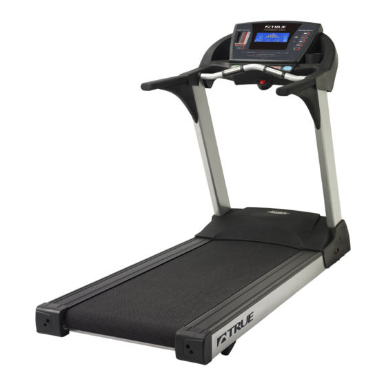
True PS 900 Manual
Hide thumbs
Also See for PS 900:
- Owner's manual (36 pages) ,
- Owner's manual (24 pages) ,
- Owner's manual (44 pages)
Table of Contents
Advertisement
Quick Links
TABLE OF CONTENTS
Introduction . . . . . . . . . . . . . . . . . . . . . . . . . . . . . . . . . . . . . . . . . . . . . . . . . . . . . . . . . .
Remove & Replace . . . . . . . . . . . . . . . . . . . . . . . . . . . . . . . . . . . . . . . . . . . . . . . . . . . . .
Troubleshooting . . . . . . . . . . . . . . . . . . . . . . . . . . . . . . . . . . . . . . . . . . . . . . . . . . . . . . .
Test Procedures . . . . . . . . . . . . . . . . . . . . . . . . . . . . . . . . . . . . . . . . . . . . . . . . . . . . . . .
Parts List . . . . . . . . . . . . . . . . . . . . . . . . . . . . . . . . . . . . . . . . . . . . . . . . . . . . . . . . . . . .
Exploded View . . . . . . . . . . . . . . . . . . . . . . . . . . . . . . . . . . . . . . . . . . . . . . . . . . . . . . . .
Electronics Diagram . . . . . . . . . . . . . . . . . . . . . . . . . . . . . . . . . . . . . . . . . . . . . . . . . . . .
Wiring Diagram . . . . . . . . . . . . . . . . . . . . . . . . . . . . . . . . . . . . . . . . . . . . . . . . . . . . . . .
LED Position Diagram . . . . . . . . . . . . . . . . . . . . . . . . . . . . . . . . . . . . . . . . . . . . . . . . . . .
2-5
6-18
19-29
30-42
43-46
47
48
49
50
Advertisement
Table of Contents

Related Manuals for True PS 900


Summary of Contents for True PS 900
-
Page 1: Table Of Contents
TABLE OF CONTENTS Introduction ............Remove &... -
Page 2: Introduction
UNIT SPECIFICATIONS Application: Light Commercial Unit Weight: 312 lbs Unit Dimensions: 31.5”Wx 82”L Maximum User Weight: 350 lbs Motor: 4 hp DC Treadbelt Area: 22”W x 60”L Power Supply: 115V AC Display: Custom LCD Warranty: Frame (Lifetime) Parts (3) Labor (1) - Page 3 Only qualified personnel, (as outlined below), should install, operate and maintain this equipment. Always properly ground equipment and lock out electric power (de-energize) before maintenance (unless instructed to power equipment as part of a test procedure or an electrical check). TRUE recommends the use of safety glasses when servicing equipment.
- Page 4 QUALIFIED PERSONNEL For the purpose of this manual, a qualified person is one that is: a. Preferably, a technician certified through TRUE Fitness Technology, Inc. service school and / or a technician from an authorized TRUE dealership. b. A service technician trained on comparable fitness equipment, currently employed as a fitness equipment technician and experienced with the hazards involved with its installation, operation and maintenance.
- Page 5 ALERT INDICATORS Alert indicators appear throughout the procedures of this manual to indicate potential hazard that the user may encounter. DANGER indicates an imminently hazardous situation DANGER which, if not avoided, will result in death or serious injury. WARNING indicates a potentially hazardous situation which, if not avoided, WARNING could result in serious injury.
-
Page 6: Remove & Replace
REMOVE & REPLACE... - Page 7 Display Board Total Time Required: Prerequisite Removals: None 20:00 Tools Required: #1 & #2 Phillips Screwdriver CAUTION Overlay Turn the power to the unit off and un- plug treadmill from the wall to avoid damaging equipment. #2 Phillips Screws Computer Board Rear Cover Summary of Procedure:...
- Page 8 Contact Heart Rate Grips Total Time Required: Prerequisite Removals: 20:00 None Tools Required: Razor Knife or Pocket Knife, #1 Phillips Screwdriver Quick-slide Sensor Connector Plate Sensor Plate Male Blade Lead Connector Contact heart rate sensor grip assembly #1 Phillips Grip Assembly Screws Summary of Procedure: 1.
- Page 9 Motor Cover Lift (For complete removal see pedestal procedure) Total Time Required: Prerequisite Removals: 5:00 None Tools Required: #2 Phillips Screwdriver, Bungie Cord CAUTION Turn the power to the unit off and unplug the treadmill from the wall to avoid injury. #2 Phillips Pedestal Screws...
- Page 10 Pedestal (Uprights) Total Time Required: Prerequisite Removals: 15:00 None Tools Required: #2 Phillips Screwdriver, 5 mm Allen Wrench CAUTION Turn the power to the unit off and unplug the treadmill from the wall to avoid injury. Pedestal #2 Phillips Screws Motor Cover Allen Bolts...
- Page 11 Controller (Lower Board) Total Time Required: Prerequisite Removals: 15:00 Motor Cover Lift Tools Required: #2 Phillips Screwdriver DANGER Turn the power to the unit off and unplug the treadmill from the wall to avoid se- rious injury or death. #2 Phillips Screws Summary of Procedure: 1.
- Page 12 Incline Motor Total Time Required: Prerequisite Removals: 45:00 Motor Cover Lift Tools Required: Flathead Screwdriver, #2 Phillips Screwdriver, 8 mm Allen Wrench, 17 mm Open-Ended wrench, Rubber Mallet DANGER Turn the power to the Incline Motor unit off and unplug the treadmill from the wall to avoid se- rious injury or death.
- Page 13 Motor Total Time Required: Prerequisite Removals: 20:00 Motor Cover Lift Tools Required: 6 mm Allen Wrench, 12 mm Open- Ended Wrench, Needlenose Pliers, 8mm Allen 8 mm Hex Socket Bolts Motor DANGER Turn the power to the unit off and unplug the treadmill from Flywheel the wall to avoid se-...
- Page 14 Straddle Cover Rear End Caps Total Time Required: Prerequisite Removals: 5:00 None Tools Required: #2 Phillips Screwdriver Straddle Cover Rear End Cap (R) #2 Phillps Screws Straddle Cover Rear End Cap (L) Summary of Procedure: 1. Using a #2 Phillips screwdriver, remove two screws (one per cap) and remove the rear end caps.
- Page 15 Straddle Covers Total Time Required: Prerequisite Removals: 10:00 Straddle Cover Rear End Caps Tools Required: 13 mm Open-Ended Wrench Straddle Covers 13mm Bolts Summary of Procedure: 1. Tilt the unit on its side to access the underside of the treadmill. 2.
- Page 16 Front Roller Total Time Required: Prerequisite Removals: 30:00 Motor Cover Lift, Straddle Cover Rear End Caps Tools Required: 6 mm Allen Wrench, 8 mm Hex Socket, 12 mm & 14 mm Open-Ended Wrenches WARNING Front Roller Frame Turn the power to the unit off and unplug the treadmill from the wall to avoid serious injury.
- Page 17 Rear Roller Total Time Required: Prerequisite Removals: 15:00 Straddle Cover Rear End Caps, Straddle Covers Tools Required: 8 mm Hex Socket WARNING Turn the power to the unit off and unplug the treadmill from the wall Rear to avoid serious injury. Roller 8mm Allen Bolts...
- Page 18 Belt & Deck Total Time Required: Prerequisite Removals: 50:00 Straddle Cover Rear End Caps, Straddle Covers, Motor Cover Lift, Front Roller, Rear Roller Tools Required: 5 mm Allen Wrench WARNING Turn the power to the unit off and unplug the treadmill from the wall to avoid serious injury.
-
Page 19: Troubleshooting
TROUBLESHOOTING... - Page 20 Diagnostics 1. Enter diagnostics mode by holding the buttons while placing the safety key. 2. The message center will display: “Diagnostics”. 3. Press the button once to display Total Hours, (in whole hours). 4. Press the button again to display Distance, (in miles to two digits past the decimal point).
- Page 21 Calibration 1. Enter calibration mode by holding the keys while placing the safety key. 2. In the message center window will be displayed: “Press Start to Calibrate”. 3. Press to begin calibration. 4. Treadmill will elevate and speed up/slow down. 5.
- Page 22 Error Messages Error Code Error Description S1 L LUBE DECK NEEDS TO BE LUBRICATED S2 C CLEAN MACHINE NEEDS TO BE CLEANED S3 M MOTOR BRUSHES ON MOTOR NEED TO BE CHECKED E5 S SPEED SENSOR CANNOT READ SPEED SENSOR E1 S STALL CONNOT READ INCLINE COMMAND E1 I INCLINE...
- Page 23 No Display/No Power To Treadmill Summary of Procedure: DANGER This test will expose the technician to a potential shock hazard. Exercise caution when performing procedure. 1. Check the wall outlet for 110V to 120V AC. See Grounded Outlet Test. 2. If the AC test is good on the wall outlet, remove the motor cover and check the AC and VCON LEDs on the controller.
- Page 24 No Belt Movement (E5 S SPEED SENSOR/S3M MOTOR) Summary of Procedure: DANGER This test will expose the technician to a potential shock hazard. Exercise caution when performing procedure. 1. Check speed LED on the controller. The speed LED should blink on and off as the magnet passes by the speed sensor.
- Page 25 Heart Rate Not Functional/Erratic Readings Summary of Procedure: 1. Locate any RF sources and use a process of elimination. Common sources of RF interference include: invisible fences, wi-fi networks, cordless phones, cell phones, radios, home security sensors, etc. 2. Verify the Polar HR with an alternate heart rate strap. If the Polar strap is good, replace the Polar HR receiver.
- Page 26 Elevation Not Functional (E1 S STALL/E1 I INCLINE/E1 R RANGE) Summary of Procedure: DANGER This test will expose the technician to a potential shock hazard. Exercise caution when performing procedure. 1. Enter calibration mode and check the incline value. 2. Verify that the number is between 220 and 230. 3.
- Page 27 Speed Fluctuations (E2 O OVERSPEED) Summary of Procedure: 1. Check for high friction by performing a Push-off test, (Refer to the push-off test procedure). If the machine has a high friction, it can lead to excessive draw on the motor. If this happens, the motor may try to overcompensate and throw an error code.
- Page 28 EEPROM Error (E3 E EEPROM) Summary of Procedure: 1. Restart the unit. 2. If the error persists, replace the computer board.
- Page 29 Stuck Key (Key Stuck ‘KEY’) Summary of Procedure: 1. Remove the upper console rear cover and loosen the screws on the rear of the keypad electronics 1/4 turn. Refer to the upper electronics diagram. 2. If keys are still sticking, replace the keypad electronics.
-
Page 30: Test Procedures
TEST PROCEDURES... - Page 31 Grounded Outlet Test Summary of Procedure: DANGER This test will expose the technician to a potential shock hazard. Exercise caution when performing procedure. 1. Set voltmeter for Volts AC 2. Place one lead in the hot side of the outlet. 3.
- Page 32 AC Amp Draw Test Summary of Procedure: DANGER This test will expose the technician to a potential shock hazard. Exercise caution when performing procedure. 1. If amp draw is higher than expected under no load, perform a drive motor test and visually check the motor brushes before replacing.
- Page 33 This test will expose the technician to a potential shock hazard. Exercise caution when performing procedure. NOTE: You will need TRUE part number 7035700 & 70357100 wire extensions to properly perform this test. Be sure the voltmeter used for this procedure is rated to handle 15 DC amps.
- Page 34 Speed Sensor Test Summary of Procedure: WARNING This test will expose the technician to a potential pinch hazard. Exercise caution when performing procedure. 1. Remove the motor cover and verify that the speed sensor is between 1/8” to 1/4” away from the magnets on the front roller.
- Page 35 This test will expose the technician to a potential shock hazard. Exercise caution when performing procedure. NOTE: You will need quantity two of TRUE part number 70357200 wire extensions to properly perform this test. CAUTION: Disconnect power to treadmill before disconnecting and reconnecting cables.
- Page 36 Drive Motor Test Summary of Procedure: DANGER This test will expose the technician to a potential shock hazard. Exercise caution when performing procedure. NOTE: Unplug treadmill before disconnecting and reconnecting cables. 1. Unplug the treadmill and set voltmeter to Volts DC. 2.
- Page 37 Drive Belt Tension Test Summary of Procedure: WARNING This test will expose the technician to a potential pinch hazard. Exercise caution when performing procedure. 1. Place two fi ngers on the top of the drive belt and your thumb on the bottom, halfway between the front roller pulley and the drive motor pulley.
- Page 38 Running Belt Tension Test Summary of Procedure: NOTE: Running belt and running deck wear and/or lack of lubrication can cause the running belt to show symptoms similar to a loose running belt scenario. Check these conditions before adjusting running belt tension.
- Page 39 Incline Potentiometer Calibration Test Summary of Procedure: DANGER This test will expose the technician to a potential shock hazard. Exercise caution when performing procedure. CAUTION: Unplug treadmill before disconnecting and reconnecting cables. 1. Set voltmeter to Ohms. NOTE: For best results, use alligator clip leads with two pieces of wire attached to the clips. 2.
- Page 40 Voltage to Incline Motor Test Summary of Procedure: DANGER This test will expose the technician to a potential shock hazard. Exercise caution when performing procedure. NOTE: Unplug treadmill before disconnecting and reconnecting cables. 1. Set voltmeter to Volts AC. 2. Switch power to treadmill off and disconnect from wall. 3.
- Page 41 TRUE liquid silicone. NOTE: Use only TRUE supplied silicone. Use 1/4 of bottle provided with the treadmill or one packet of TRUE silicone. Lubrication should be applied every 5 1/2 months. If the machine is used for more than 3-4 hours per day, lubricate every 3 months.
- Page 42 Running Belt Alignment Procedure Summary of Procedure: 1. Power the treadmill up. 2. Press the start button and set the speed to 5 mph. 3. Watch the running belt tracking from the rear of the machine. 4. Adjust the rear roller to compensate for running belt misalignment. 5.
- Page 43 PARTS LIST/EXPLODED VIEW...
-
Page 44: Parts List
Parts List Item Part No. Description SUB-ASSEMBLIES 7PS0111 BOLT COVER 7PS0112 CONSOLE PLASTIC REAR COVER 7PS0113 BOTTLE HOLDER 7PS0114 BOLT 7PS9015 DISPLAY BOARD 7PS1117 KEY BOARD 1-10 7PS0110 CONTACT HEART RATE BOARD 7PS1119 WIRELESS HEART RATE SENSOR 7PS1118 HAND GRIP SET+ XL-488 cable 1-15 7PS9115 OVERLAY WITH INSERT, PS900... - Page 45 Parts List Item Part No. Description 7PS0014 UPRIGHT(L) 14-1 7PS9141 MODEL DECAL, PS900 7PS0015 UPRIGHT(R) 7PS0020 MOTOR COVER 20-1 7PS0201 OVAL MOTOR COVER DECAL PS 7PS0021 BOLT COVER 7PS9022B 220V DRIVE MOTOR 7PS9022 110V DRIVE MOTOR 7PS0023 BOLT 7PS0024 SPRING WASHER 7PS0025 WASHER 7PS0026B...
- Page 46 Parts List Item Part No. Description 7PS0052 BOLT 7PS0053 BOLT 7PS0055B STRADDLE COVER WITH 3M TAPE (220V) 7PS0056 REAR ROLLER 7PS0057 WASHER 7PS0058 BOLT 7PS0059 REAR END CAP (L) 7PS0060 REAR END CAP (R) 7PS0061 BOLT 7PS0062 RUBBER PAD 7PS0063 BOLT 7PS0072 LIFER U SHAPE PIN...
-
Page 47: Exploded View
78A (110V only) 220V only 116-1 116-1 220V only 220V only 25 26... -
Page 48: Electronics Diagram
Upper Console Electronics 1-11 1-13 1-12 1-10 1-12 1-13 1-10 1-11... -
Page 49: Wiring Diagram
Wiring Diagram FILTER 220V INCLINE Only MOTOR 8-pin 7-pin SAFE SW DOWN NULL WIRELESS NULL TELEMETRY MOTOR HRC GRIPS SPEED SENSOR... -
Page 50: Led Position Diagram
VCON LED Diagram I LIM RELA Y MTR SHR T M_PWM MTR VOL...
Need help?
Do you have a question about the PS 900 and is the answer not in the manual?
Questions and answers