Advertisement
π
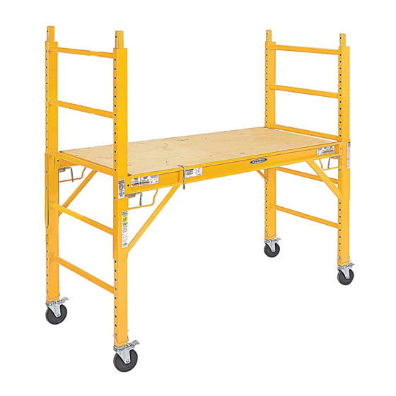
H-3800
6' STEEL ROLLING
SCAFFOLD
A
D
NOTE: Identify all components according to
chart above. If any components are missing or
damaged, contact Uline Customer Service.
1. Attach each side brace (C) to end frames (A) at the
desired platform height. Be sure the locking pins on
each side brace are fully locked in the end frame at
all 4 locations. (See Figure 1)
2. Install platform (B) so that it is fully seated and level
in both side braces (C) Be sure the deck pins are in
the engaged position. (See Figure 2)
3. Install 4 casters (E) into both end frames (A) and
secure with snap pins (D). (See Figure 3)
WARNING! Side braces must be level and
locked before using. All 4 casters must be
locked before use. Follow all applicable ANSI
and OSHA guidelines along with province and
local codes for use of the product.
PAGE 1 OF 2
1-800-295-5510
uline.ca
PARTS FOR BASE UNIT
B
E
ASSEMBLY INSTRUCTIONS FOR BASE UNIT
#
DESCRIPTION
C
A
End Frame
B
Platform
C
Side Brace
D
Snap Pin
E
5" Caster
Figure 1
Figure 2
Disengaged
Engaged
QTY.
2
1
1
4
4
Unlocked
Locked
Figure 3
Unlocked
Locked
0313 IH-3800
Advertisement
Table of Contents

Related Manuals for U-Line H-3800


Summary of Contents for U-Line H-3800
- Page 1 π H-3800 1-800-295-5510 uline.ca 6' STEEL ROLLING SCAFFOLD PARTS FOR BASE UNIT DESCRIPTION QTY. End Frame Platform Side Brace Snap Pin 5" Caster ASSEMBLY INSTRUCTIONS FOR BASE UNIT NOTE: Identify all components according to Figure 1 chart above. If any components are missing or damaged, contact Uline Customer Service.
- Page 2 PARTS FOR STACKING ADDITIONAL UNIT DESCRIPTION QTY. Guard Rail Panel/Gate Lock Pin 18" Outrigger Snap Pin 5" Caster *From additional unit. ASSEMBLY INSTRUCTIONS FOR STACKING ADDITIONAL UNIT NOTE: If the desired platform height is between Tighten 6' and 11' 6" additional unit is required. Frame WARNING! When stacking second unit, outriggers and guardrails are required.
Need help?
Do you have a question about the H-3800 and is the answer not in the manual?
Questions and answers