Table of Contents
Advertisement
Quick Links
Advertisement
Table of Contents

Related Manuals for Crystal Vision Indigo VDA110R HD


Summary of Contents for Crystal Vision Indigo VDA110R HD
- Page 1 VDA110R HD Analogue video distribution amplifier Crystal Vision Ltd., Lion Technology Park, Station Road East, Whittlesford, Cambridge, CB22 4WL, England. Tel: +44(0) 1223 497049 Fax: +44(0) 1223 497059 sales@crystalvision.tv www.crystalvision.tv...
-
Page 2: Table Of Contents
Crystal Vision VDA110R HD User Manual Contents Introduction Hardware installation Universal rear connectors Rear module connections with RM01 Rear module connections with RM09 Rear module connections with RM18 Rear module connections with RM16 Rear module connections with RM02 Rear module connections with RM10... - Page 3 Crystal Vision VDA110R HD User Manual Statesman Statesman operation Statesman operation Status and control Trouble shooting Basic fault finding guide Specification Revision 3. Specification table amended. 11/06/10 VDA110R HD User Manual R1.1 06 June 2018...
-
Page 4: Introduction
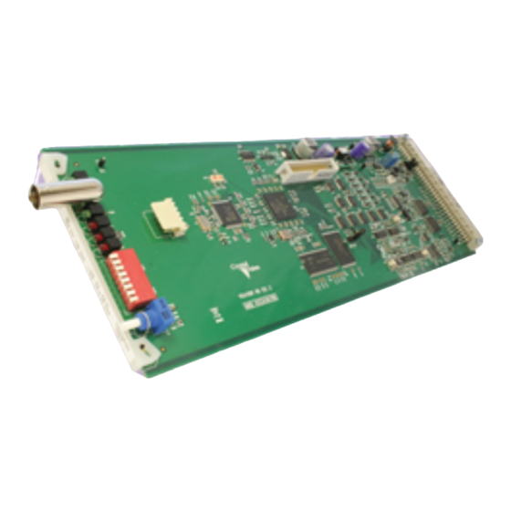
The unit plugs into the front of the rack frame, and the universal connection system allows a mixture of Crystal Vision modules in the frame. The hinged front panel of the case reveals LED indication of input status, error status and controls for cable equalisation, gain and output clamping. -
Page 5: Hardware Installation
Crystal Vision Hardware installation 2 Hardware installation The VDA110R HD single channel video distribution amplifier fits into all Crystal Vision rack frames. All modules can be plugged in and removed while the frame is powered without damage. 2.1 Universal rear connectors... -
Page 6: Rear Module Connections With Rm01
Crystal Vision Hardware installation Rear module connections with RM01 The RM01 single height rear module will give five DA outputs and will fit in all frames and all frame positions. RM01 fits in all frames Description RM01 • 24 modules in 4U, 12 in 2U, 6 in 1U &... -
Page 7: Rear Module Connections With Rm18
Crystal Vision Hardware installation Rear module connections with RM18 The RM18 double height rear module will give the maximum eleven DA outputs and will fit in all frames. In the 2U and 4U frames the RM18 can only fit in slot pairs 1-2, 3-4 etc. -
Page 8: Rear Module Connections With Rm02
Crystal Vision Hardware installation Signal Input Loop Video Loop Video Output Output Output Output Output Output Output Output Output Output Rear module connections with RM02 The RM02 quad height rear module will give eight DA outputs and will only fit in the 2U and 4U frames. -
Page 9: Rear Module Connections With Rm10
Crystal Vision Hardware installation Rear module connections with RM10 The RM10 quad height rear module has a passive input loop-through, will give seven DA outputs and will only fit in the 2U and 4U frames. The RM10 will only accept three VDA110R HD cards, the third slot down from the top being left vacant. -
Page 10: Module Configuration
Crystal Vision Hardware installation 2.2 Module configuration The VDA110R HD is equipped with an on-board jumper link to change input termination and NTSC pedestal compensation. There are several variable resistors and a variable capacitor which have been factory set. Their function is listed for reference only. -
Page 11: General Purpose Interface
Crystal Vision Hardware installation 2.3 General purpose interface Each frame slot has up to six connections ‘a’ to ‘f’ for GPI control and monitoring. These connections are available at the rear of the frame on the 26-way D-type remote connectors. - Page 12 Crystal Vision Hardware installation Note: Remote 1, Remote 3, Remote 5 and Remote 7 are 26 way high-density D-Type female sockets. Frame ground is pin 2 and +5V @500mA is pin 1 in each case. Remote 2, Remote 4, Remote 6 and Remote 8 are 26 way high-density D-Type male plugs and frame ground is pin 6 in each case and +5V @500mA is pin 15 on Remote 2 and Remote 6.
- Page 13 Crystal Vision Hardware installation Indigo DT desk top box GPI connections GPI lines ‘a’ to ‘f’ of each card connect to the rear remote connector as follows: Slot no. ‘a’ pin ‘b’ pin ‘c’ pin ‘d’ pin ‘e’ pin ‘f’ pin...
-
Page 14: Card Edge Operation
Crystal Vision Card edge operation 3 Card edge operation Once the start-up initialisation procedure is complete, the VDA110R HD card can be controlled or configured from the card edge, the active control panel or the Statesman PC interface. This chapter will concentrate on the card edge controls. - Page 15 Crystal Vision Card edge operation LED indication Location/colour Action Green Power supply OK Green Valid input signal present Present Error Input sync size >110% of expected value. (NTSC >115%) Clip Output Luma levels >110% of peak white Output Luma level <15% of peak white for an extended...
- Page 16 Crystal Vision Card edge operation Alarm Both the clip and black alarms are presented on the frame rear connectors as GPI alarms. Under certain circumstances such as with a black and burst or tri level input, these alarms can nuisance trigger. Setting DIP switch 5 to down will disable these GPIs.
-
Page 17: Using The Front Control Panel
This operational guide assumes that the panel has been set up according to the panel setup procedure described in the Crystal Vision Control Panel manual. It is ESSENTIAL that the panel setup procedure is followed and any old or unknown Note: passwords cleared prior to using the panel for the first time. -
Page 18: Updating The Display
Using the front control panel • Rotary control – shaft encoder used to select options or variable data Please refer to the Crystal Vision Control Panel manual for details of the Panel Setup, Lock Panel and Note: Diagnostic menus. Selecting a VDA110R HD To select a particular card in a frame, press the DEVICE key to go to the Device menu. -
Page 19: The Vda110R Hd Active Panel Menu Structure
Crystal Vision Using the front control panel 4.1 The VDA110R HD active panel menu structure At any time the main top-level menu (Home) is obtained by pressing the HOME key. From the Home menu further selections can be made. Active function keys are indicated by illuminated, integrated LEDs. -
Page 20: The Status Menu
Crystal Vision Using the front control panel The Status menu Pressing button F1 from the Home menu will enter the Status menu. This menu is traversed by rotating the shaft control. No changes can be made from this menu as it is read only. -
Page 21: The Control Menu
Crystal Vision Using the front control panel Adjusting cable equalisation and input gain Cable equalisation is continuously variable from 0m to 300m. Video gain is continuously variable with an adjustment range of >± 3.0dB Note: The cable equalisation has been optimised for 0-6Mhz operation. It will be less effective at frequencies of up to 30Mhz. -
Page 22: Reset Menu
Crystal Vision Using the front control panel Alarm Both the clip and black alarms are presented on the frame rear connectors as GPI alarms. Under certain circumstances such as with a black and burst or tri level input these alarms can nuisance trigger. -
Page 23: Statesman
Statesman 5.1 Statesman operation The Crystal Vision Statesman PC control software is designed to control a range of Crystal Vision modules via serial control from a PC. Statesman provides a user friendly means of configuring and operating Crystal Vision modules with the benefit of “see-at-a- glance”... -
Page 24: Status And Control
Crystal Vision Statesman Status and control The board status is shown using a mixture of simulated LEDs and text information. As a general rule a green LED shows a good condition such as input present or audio groups present. An amber LED will give a warning as with sync error, Luma high or dark. If an LED turns red this is a fault condition so input present will turn red if the input should go away. - Page 25 Crystal Vision Statesman Video gain The video gain is continuously adjustable between 70% and 140% by using the video gain slider control. Cable equalisation Cable equalisation is continuously adjustable between 0m and 300m by using the cable equalisation slider control.
- Page 26 Crystal Vision Statesman Sync filter To prevent large negative chroma excursion affecting the DC restoration an input filter to the sync separator circuitry has been included. Selecting On will activate this filter should it be required. Note, it is not recommended to activate this filter when an HD video signal is present as this will disrupt the DC restoration.
-
Page 27: Trouble Shooting
Crystal Vision Trouble shooting 6 Trouble shooting The front edge of the card provides useful power rail and video monitoring in addition to card-edge controls and status LEDs. VDA110R HD front edge view Video monitoring A monitoring output is provided by the board edge BNC connector. -
Page 28: Basic Fault Finding Guide
Crystal Vision Trouble shooting Basic fault finding guide The Power OK LEDs are not illuminated Check that the frame PSU is functioning – refer to the appropriate frame manual for detailed information Check that the card is seated correctly in the frame... -
Page 29: Specification
Crystal Vision Specification 7 Specification General Dimensions 100mm x 266 mm module with DIN 41612 connector Weight 160g Power consumption Inputs Video 1 analogue. Input loop-through available with selected rear modules Outputs Number and type: 11 (maximum) cable-equalised analogue Gain adjustment Continuous adjustment: Greater than ±... - Page 30 Crystal Vision Specification Status monitoring LED display Front of card edge visual monitoring with LED indicators to indicate: PSU rails present Input present Dark, Clip, Sync error VDA110R HD User Manual R1.1 06 June 2018...
Need help?
Do you have a question about the Indigo VDA110R HD and is the answer not in the manual?
Questions and answers