Table of Contents

Related Manuals for Parker CDAS HL 050


Summary of Contents for Parker CDAS HL 050
- Page 1 Rev H Preventative Maintenance Guide: 17 873 0007 Compressed Air Dryers Medium Flow Dryers CDAS HL 050 - CDAS HL 085 OFAS HL 050 - OFAS HL 085 FBP HL 050 - FBP HL 085 Installation, Operation and Maintenance Instructions (EN)
- Page 2 CONTENTS – Safety Information – Configure Inlet Valves Configuration (N/C or N/O) - Configure Temperature Units to be Displayed – Markings and Symbols – Commissioning - Controller Setup Advanced – Dryer Model Number Identification Installation - CDAS HL / OFAS HL / FBP HL Dryer Auxiliary –...
- Page 3 CONTENTS – Service Intervals – Remote Alarm Connection - Dedicated Dewpoint Alarm – Preventative Maintenance Kits – 4-20mA Dewpoint Retransmission – Using the 4-20mA Signal – Technical Specification – MODBUS Connectivity – Approvals Compliance and Exemptions – MODBUS Strings – Weights and Dimensions –...
- Page 4 SAFETY Medium Flow Compressed Air Dryers - IOMI.
- Page 5 If the user employs an operating procedure, item of equipment or a method of working which is not specifically recommended by Parker the user must ensure that the equipment will not be damaged or become hazardous to persons or property.
- Page 6 MARKINGS AND SYMBOLS The following markings and international symbols are used on the equipment or within this user guide: Caution, Read the User Guide. Wear ear protection. Risk of electric shock. Pressurised components on the system. Highlights actions or procedures which, if not Remote control.
- Page 7 RECEIVING AND INSPECTING THE EQUIPMENT Medium Flow Compressed Air Dryers - IOMI.
- Page 8 On delivery of the equipment check the crate and its contents for damage. If there are any signs of damage to the crate, or there are any parts missing please inform the delivery company immediately and contact your equipment supplier or local Parker sales company. Transportation The equipment must be kept upright at all times, including during transportation, storage and unpacking.
- Page 9 MODEL OVERVIEW Medium Flow Compressed Air Dryers - IOMI.
- Page 10 Model Overview CDAS HL / OFAS HL / FBP HL are complete purification systems designed to reduce the major contaminants found in a compressed air system and deliver air purity that meets or exceeds the highest classifications of ISO 8573-1:2010 (the international standard for compressed air purity).
- Page 11 MODEL: OFAS - OIL FREE AIR SYSTEM Number of Number of Contaminants Treated Purification Stages ISO 8573-1:2010 Classification RANGE (With Optional (With Optional (Pressure Dewpoint) Water Separator) Water Separator) 2:3:0 2:2:0 2:1:0 Oil Free Air System OFAS (10) (≤-20°C) (≤-40°C) (≤-70°C) General Purpose Coalescing Filter...
- Page 12 MODEL: FBP - FOOD BEVERAGE PHARMACEUTICAL Number of Number of Contaminants Treated Purification Stages ISO 8573-1:2010 Classification RANGE (With Optional (With Optional (Pressure Dewpoint) Water Separator) Water Separator) 1:2:0 1:1:0 Food Beverage Pharmaceutical (10) (≤-40°C) (≤-70°C) General Purpose Coalescing Filter Oil Vapour Reduction Filter For the reduction of water and oil...
- Page 13 OVERVIEW OF THE EQUIPMENT Medium Flow Compressed Air Dryers - IOMI.
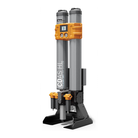
- Page 14 OVERVIEW OF THE EQUIPMENT CDAS - Clean Dry Air System Representation of Models CDAS HL050 to CDAS HL070 Representation of Models CDAS HL075 to CDAS HL085 DESCRIPTION DESCRIPTION Display Dewpoint sensor Column 1 pressure gauge Control box Column 2 pressure gauge Column caps General purpose coalescing filter (Grade AO) Adjustable purge disc...
- Page 15 OFAS - Oil Free Air System Representation of Models OFAS HL050 to OFAS HL070 Representation of Models OFAS HL075 to OFAS HL085 DESCRIPTION DESCRIPTION Display Dewpoint sensor Column 1 pressure gauge Control box Column 2 pressure gauge Column caps General purpose coalescing filter (Grade AO) Adjustable purge disc High efficiency coalescing filter (Grade AA) Pallet truck lifting points...
- Page 16 FBP - Food Beverage Pharmaceutical Representation of Models FBP HL050 to FBP HL070 Representation of Models FBP HL075 to FBP HL085 DESCRIPTION DESCRIPTION Display Dewpoint sensor Column 1 pressure gauge Control box Column 2 pressure gauge Column caps General purpose coalescing filter (Grade AO) Adjustable purge disc High efficiency coalescing filter (Grade AA) Pallet truck lifting points...
- Page 17 INSTALLATION AND COMMISSIONING Medium Flow Compressed Air Dryers - IOMI.
-
Page 18: Table Of Contents
INSTALLATION AND COMMISSIONING Only competent personnel trained, qualified, and approved by Parker Hannifin should perform installation, commissioning, service and repair procedures. Warning COMMISSIONING CHECK LIST TICK WHEN TASK PAGE COMMENTS Recommended System Layout System Components / piping installation Locating the Equipment... - Page 19 RECOMMENDED SYSTEM LAYOUT CDAS HL / OFAS HL / FBP HL dryers can be installed directly after an air compressor or downstream of a wet air receiver. The preferred method of installation is downstream of a wet air receiver as the air receiver acts as a pre-cooler / liquid separator and is effective at protecting the dryer from bulk liquid contamination and small temperature spikes.
-
Page 20: Mechanical Installation
LOCATING THE EQUIPMENT Environment The equipment should be located indoors in an environment that protects it from direct sunlight, moisture, and dust. Changes in temperature, humidity, and airborne pollution will affect the environment in which the equipment is operating and may impair the safety and operation. - Page 21 SIDE MOUNTING THE REAR PANEL For installations where space is limited (for example if the dryer is placed against a wall), it maybe beneficial to install the rear panel assembly to the side of the dryer to provide easier access to the electrical control box, dewpoint sensor & control valves. Important Notes: •...
- Page 22 Securing the Dryer Mounting holes are provided in the feet of the dryer. Once the dryer has been positioned in its final location ensure that it is securely fixed in place using M15 fixing bolts. Attach the Exhaust Silencer The dryer is supplied with an exhaust silencer. If the dryer is to be located in a noise sensitive area, exhaust air can also be remotely piped away.
-
Page 23: Electrical Installation
ELECTRICAL INSTALLATION A fully qualified electrical engineer must undertake all field wiring and electrical work in accordance with local regulations. Warning During installation and commissioning, the controller must be connected to a suitable power supply and configured using the dip switches found on the main control board. - Page 24 Configure Inlet Valves Configuration (N/C - Normally Closed or N/O - Normally Open) • Default Factory Setting is Normally Closed. • If a dryer is required to operate in a Normally Open configuration, reconfigure Dipswitch Array 1, DIL Switch 7 as shown: DIPSWITCH ARRAY (1) DIL SWITCH FUNCTION...
-
Page 25: Commissioning - Controller Setup Advanced Installation
Commissioning – Controller Setup Advanced Installation To access the additional functionality offered by the controller, the following settings must be activated and configured to match the requirements of the installation: Remote Stop / Start (Refer to page 25) • Dipswitch configuration required •... -
Page 26: Remote Stop / Start Connection
Remote Stop / Start Connection CDAS HL / OFAS HL / FBP HL dryers can be configured to enable remote shut down and start up (Stop / Start) of the dryer. This requires a 24VDC signal to be supplied to the remote stop digital input (RC) on the control board and setting of DIL Switch 8 on Dipswitch Array 1 to enable DIPSWITCH ARRAY (1) DIL SWITCH... -
Page 27: Purge Economy Connection
Important Notes: • The default inlet valve configuration for CDAS HL / OFAS HL / FBP HL is Normally Closed (N/C). • In this configuration, when the remote switch is closed and the ½ cycle is completed, the inlet and exhaust valve will be closed. There will be no air flow through the dryer, protecting the desiccant bed. - Page 28 Purge Economy Operation Compressor On Load As the compressor is operating, the relay connection is open and the dryer will be operating normally, drying the compressed air. Compressor Off Load When the air compressor reaches its set operating pressure and goes off load, the relay in the compressor will close.
- Page 29 Remote Alarm Connection – General Fault Alarm The CDAS HL / OFAS HL / FBP HL dryer controller includes a general fault alarm used to indicate power loss, dewpoint alarm or dewpoint sensor failure. When the general fault alarm is active, an icon will be visible on the display. The general fault alarm is linked to a relay providing volt free contacts: Normally Closed (N/C), Normally Open (N/O), and a Common (Com) These contacts are rated 24Vdc and 230Vac @ 1A and can be used for remote alarm indication.
- Page 30 Remote Alarm Connection - Dedicated Dewpoint Alarm The CDAS HL / OFAS HL / FBP HL dryer controller includes the ability to connect a dedicated dewpoint alarm relay that will activate only if a dewpoint alarm occurs. This function requires the connection of an additional relay (not supplied) and activation by a trained engineer using the ADS service software.
-
Page 31: 4-20Ma Dewpoint Retransmission
CDAS HL / OFAS HL / FBP HL controller PCB. HYGROMETER Connection of the 4-20mA retransmission is identical for both the Parker Dewpoint Sensor (PDS) and Hygrometer. An 800Ω (+20 Ω / -0 Ω) resistor will be required in series in the loop circuit. - Page 32 Accuracy Range example: measured value = 12mA measure value = 14mA It should be noted that the accuracy of measured mA reflects the accuracy of the Parker Dew Point Sensor ±4°C. Hygrometer 4-20 mA output Dewpoint Calculation PARKER DEWPOINT SENSOR Current -100 Dewpoint=((mA-4)×7.5)-100...
-
Page 33: Modbus Connectivity
Even Number of Stop Bits Modbus Unit ID (Node) The parameters for baud rate, data bits, parity, stop bits and unit ID can all be changed by a trained service engineer using the Parker ADS service software. • When connected, the MODBUS icon will be shown on the display •... -
Page 34: Modbus Strings
MODBUS Strings HOLDING HOLDING REGISTER HOLDING HOLDING REGISTER NUMBER DESCRIPTION DETAILS NUMBER DESCRIPTION DETAILS REGISTER FUNCTION CODE 1 REGISTER FUNCTION CODE2 External Input: Purge 0: De-asserted 1: Asserted Economy Dewpoint Alarm 0: Reset 1: Active External Input: ECO 0: De-asserted 1: Asserted External Input: Remote 0: De-asserted 1: Asserted Stop... - Page 35 MODBUS Strings Continued.. HOLDING HOLDING REGISTER HOLDING HOLDING REGISTER NUMBER DESCRIPTION DETAILS NUMBER DESCRIPTION DETAILS REGISTER FUNCTION CODE 3 REGISTER FUNCTION CODE 3 ADS Config: Custom EST Software Version Range: -120C to 0C Setpoint Graphics Version ADS Config: Service 500 to 30,000Hours Interval (Filter) Run Time (Seconds) ADS Config: Inlets N/O...
- Page 36 After changing any parameters, the control board must be power cycled (Power off / Power On) for the changes to be accepted. To change the baud rate on the CDAS HL /OFAS HL / FBP HL dryers it is necessary to connect the dryer to a PC using the Parker ADS service software to communicate with the control board.
- Page 37 CDAS HL OFAS HL FBP HL OPERATION Medium Flow Compressed Air Dryers - IOMI.
- Page 38 OVERVIEW OF OPERATION CDAS HL / OFAS HL / FBP HL purification systems are based around a heatless adsorption dryer and associated pre filtration and post filtration. Adsorption dryers are designed for the treatment of water vapour only and therefore require pre-treatment of the incoming compressed air to operate correctly and protect the adsorbent desiccant bed.
- Page 39 CDAS HL / OFAS HL / FBP HL OPERATION CDAS HL / OFAS HL / FBP HL Dryer Cycle Times and Operation CDAS HL / OFAS HL / FBP HL dryers are designed to use two drying columns to deliver a constant outlet dewpoint. A full cycle is the time it takes the dryer to fully utilise the desiccant material in both columns.
- Page 40 Important Note: Purge air volume must be set up during commission to supply the correct amount of purge air required for efficient regeneration. Refer to page 21 for purge volume setting. Re-pressurisation (30 seconds) After 150 seconds (2 ½ minutes) of regeneration, the exhaust valve will close, and the purge air will re- pressurise the off-line column.
- Page 41 Seconds Important Notes: Should an error occur with either the Parker Dewpoint Sensor (PDS) or the Dewpoint Hygrometer, a yellow box will appear around the dewpoint icon. The outlet dewpoint figure will be replaced with “---“and “ERR” will be displayed.
- Page 42 3 half cycles can be modified by a trained engineer (please note, that changing these parameters can affect the performance of the dryer and should only be carried out following consultation with Parker) Purge Economy Purge economy requires a physical connection between the air compressor and the dryer and is designed to save energy (by stopping purge air) when the air compressor goes off load.
- Page 43 OPERATING THE EQUIPMENT Medium Flow Compressed Air Dryers - IOMI.
- Page 44 The type of dewpoint sensor fitted differs depending upon the dryer range and outlet dewpoint. The table below highlights the sensors used. Pressure Dewpoint Dryer Model -20°C /-40°C -70°C (-4°F /-40°F) (-100°F) Parker Dewpoint Sensor (PDS) Hygrometer CDAS HL Parker Dewpoint Sensor (PDS) Hygrometer OFAS HL Hygrometer Hygrometer...
- Page 45 OPERATING THE DRYER Displays and Indicators Standard CDAS HL / OFAS HL / FBP HL dryers are fitted with a 3.45" colour TFT display (Please note - this is not a touchscreen). Below is an example of the basic display format. Important Note: OFAS &...
- Page 46 Screen Icons "CDAS" = Indicates controller has been set up for a "OFAS" = Indicates controller has been set up for a CDAS dryer OFAS dryer "FBP" = Indicates controller has been set up for a FBP Flashing "+" = Dryer heartbeat, used to identify dryer controller and screen are communicating "Numerical value %"...
- Page 47 When the dryer is operating, the outlet dewpoint will be shown in real time in the upper left corner of the display. CDAS HL and OFAS HL -20°C / -40°C PDP dryers are supplied as standard with the Parker Dewpoint Sensor (PDS).
- Page 48 Display During A Typical Drying Cycle (CDAS HL shown) COLUMN VALVE VALVE STATUS COLUMN STATUS ENERGY SAVING PRESSURISED Inlet 1 Open Column 1 On-line Drying Exhaust Open Inlet 2 Closed Column 2 Off-line Regenerating COLUMN VALVE VALVE STATUS COLUMN STATUS ENERGY SAVING PRESSURISED Inlet 1...
- Page 49 COLUMN VALVE VALVE STATUS COLUMN STATUS ENERGY SAVING PRESSURISED Inlet 1 Closed Column 1 Off-line Regenerating Exhaust Open Inlet 2 Open Column 2 Off-line Drying COLUMN VALVE VALVE STATUS COLUMN STATUS ENERGY SAVING PRESSURISED Inlet 1 Closed Column 1 Off-line Repressurisation Exhaust Closed...
- Page 50 Dewpoint Alarm Delay at Start Up Following application of power there is a dewpoint alarm delay of 30 minutes (customisable by a trained engineer using the Parker ADS service software). During the alarm delay period, should the dryer outlet dewpoint be worse than the dewpoint alarm setpoint, the alarm relay will not be triggered.
- Page 51 CDAS HL / OFAS HL / FBP HL Display Icons Remote Stop Connected – Remote Switch Open – Dryer Operating Remote Stop Connected – Remote Switch Closed – Dryer Stopped (OFAS model shown) (OFAS Model shown) Yellow Filter – Static Spanner Image - Filter Service Due Yellow Dryer Columns –...
- Page 52 PREVENTATIVE MAINTENANCE Medium Flow Compressed Air Dryers - IOMI.
- Page 53 Replace inlet / outlet / control air filter elements. Filtration Replace inlet filter / control air filter float drains. Replace Parker Dewpoint Sensor or Dryer Dewpoint Hygrometer transmitter Dryer Replace the outlet check ball Replace the inlet valves (x 2), exhaust valve...
- Page 54 PREVENTATIVE MAINTENANCE KITS - CDAS HL 050 -085 CATALOGUE DESCRIPTION ORDER QTY NUMBER M12.FSK.0002 12 Month Filter Service Kit (-20 and -40 dryers) CDAS HL 050 - CDAS HL 055 (x1) M12.FSK.1002 12 Month Filter Service Kit (-70 dryer) CDAS HL 050 - CDAS HL 055 (x1) M12.FSK.0003...
- Page 55 PREVENTATIVE MAINTENANCE KITS - OFAS HL 050 - 085 CATALOGUE DESCRIPTION ORDER QTY NUMBER M12.FSK.0011 12 Month Filter Service Kit (-20 and -40 dryers) OFAS HL 050 - OFAS HL 055 (x1) M12.FSK.1011 12 Month Filter Service Kit (-70 dryer) OFAS HL 050 - OFAS HL 055 (x1) M12.FSK.0012 12 Month Filter Service Kit (-20 and -40 dryers)
- Page 56 PREVENTATIVE MAINTENANCE KITS - FBP HL 050 - 085 CATALOGUE DESCRIPTION ORDER QTY NUMBER M12.FSK.0111 12 Month Filter Service Kit (-20 and -40 dryers) FBP HL 050 - FBP HL 055 (x1) M12.FSK.1111 12 Month Filter Service Kit (-70 dryer) FBP HL 050 - FBP HL 055 (x1) M12.FSK.0112 12 Month Filter Service Kit (-20 and -40 dryers)
- Page 57 12 MONTH PM KIT CONTENTS - CDAS HL 050 - 085 CDAS HL -20 C PDP / -40 C PDP dryers CATALOGUE NO'S DESCRIPTION CONTENTS AO grade filter elements (x2) AA grade filter elements (x2) Filter Drains (x3) M12.FSK.0002 Silencer element (x1) M12.FSK.0003...
- Page 58 12 MONTH PM KIT CONTENTS - FBP HL 050 - 085 UPGRADE (12 Month service kit including hygrometer upgrade kit) FBP HL -20 C PDP / -40 C PDP dryers CATALOGUE NO'S DESCRIPTION CONTENTS AO grade filter elements (x2) AA grade filter elements (x3) Filter Drains (x3) Silencer element (x1) M12.FSK.0111...
- Page 59 TECHNICAL SPECIFICATION Medium Flow Compressed Air Dryers - IOMI.
- Page 60 TECHNICAL SPECIFICATION Dryer Performance PRESSURE ISO 8573-1:2010 PRESSURE ISO 8573-1:2010 PRESSURE ISO 8573-1:2010 DEWPOINT WATER DEWPOINT WATER DEWPOINT WATER DRYER MODEL (STANDARD) CLASSIFICATION (OPTIONAL) CLASSIFICATION (OPTIONAL) CLASSIFICATION (STANDARD) (OPTIONAL) (OPTIONAL) CDAS HL Class 2.2.2 -100 Class 2.1.2 Class 2.3.2 OFAS HL Class 2.2.0 -100 Class 2.1.0...
- Page 61 Product Selection & Correction Factors For correct operation, compressed air dryers must be sized using for the minimum pressure, maximum temperature and maximum flow rate of the installation. To select a dryer, first calculate the MDC (Minimum Drying Capacity) using the formula below then select a dryer from the flow rate table above with a flow rate equal to or above the MDC.
- Page 62 APPROVALS COMPLIANCE AND EXEMPTIONS Approvals APPROVALS, ACCREDITATIONS AND ASSOCIATIONS Safety and Electromagnetic Compatibility This equipment has been tested and complies with the following European Standards: BS EN 60204-1:2006 (Including: Amendment1:2009) - Safety of machinery. Electrical equipment of machines. General requirements. EN61326: 2006 - Electrical Equipment for Measurement, Control, and Laboratory use, EMC Requirements.
- Page 63 CDAS HL WEIGHTS AND DIMENSIONS DRYER DIMENSIONS WEIGHT DRYER MODEL CDAS HL 050 1133 44.6 22.0 19.3 16.4 121.5 4.78 371.3 14.62 16.14 CDAS HL 055 1313 51.7 22.0 19.3 16.4 121.5 4.78 371.3 14.62 16.14 CDAS HL 060 1510 59.4...
- Page 64 OFAS HL WEIGHTS AND DIMENSIONS DRYER DIMENSIONS WEIGHT DRYER MODEL OFAS HL 050 1133 44.6 22.0 19.3 16.4 96.5 3.80 371.3 14.62 16.14 OFAS HL 055 1313 51.7 22.0 19.3 16.4 96.5 3.80 371.3 14.62 16.14 OFAS HL 060 1510 59.4 22.0 19.3...
- Page 65 FBP HL WEIGHTS AND DIMENSIONS DRYER DIMENSIONS WEIGHT DRYER MODEL FBP HL 050 1133 44.6 22.0 19.3 16.4 96.5 3.80 371.3 14.62 16.14 FBP HL 055 1313 51.7 22.0 19.3 16.4 96.5 3.80 371.3 14.62 16.14 FBP HL 060 1510 59.4 22.0 19.3...
- Page 66 In the unlikely event that a problem occurs on the equipment, this troubleshooting guide can be used to identify the probable cause and remedy. Troubleshooting should only be attempted by competent personnel. All major repair and calibration work should be undertaken by a Parker trained, qualified and approved engineer. Warning Dewpoint Failure...
- Page 67 Loss of Outlet Dewpoint If outlet dewpoint on external hygrome- Check outlet dewpoint downstream of the ter does not match Confirm loss of dewpoint dryer with an with external dewpoint on dryer display - check sen- hygrometer. sor the dryer dewpoint sensor Check sizing Sizing correct, continue below.
- Page 68 Loss of Outlet Dewpoint Continued... Remove any particulate with low pres- Check Parker Dewpoint Sensor Check the Parker Dewpoint Sensor is clean sure compressed air Switch off dryer once both columns have depressurised Depressurise Dryer Remove column top caps Check cartridge sealing on column showing...
- Page 69 If the inlet pressure has changed ensure that the filters and dryer are re-sized accordingly. Contact Parker for details on particle counting and air quality air measurement. Check the documentation supplied by the compressor manufacturer for The compressor is not functioning correctly.
- Page 70 Declaration of Conformity Parker Parker Hannifin Manufacturing Limited GSFE Dukesway,Team Valley Trading Estate,Gateshead, Tyne & Wear,NE11 0PZ, UK Compressed Air Dryer CDASHL050, CDASHL055, CDASHL060, CDASHL065, CDASHL070, CDASHL075, CDASHL080, CDASHL085 OFASHL050, OFASHL055, OFASHL060, OFASHL065, OFASHL070, OFASHL075, OFASHL080, OFASHL085 PE(S)R 2016 (as amended) SI 2016 No. 1105...
- Page 71 Declaration of Conformity Parker Parker Hannifin Manufacturing Limited GSFE Dukesway,Team Valley Trading Estate,Gateshead, Tyne & Wear,NE11 0PZ, UK Compressed Air Dryer CDASHL050, CDASHL055, CDASHL060, CDASHL065, CDASHL070, CDASHL075, CDASHL080, CDASHL085 OFASHL050, OFASHL055, OFASHL060, OFASHL065, OFASHL070, OFASHL075, OFASHL080, OFASHL085 2014/68/EU 2014/35/EU 2014/30/EU...
- Page 72 Declaration of Conformity Parker Parker Hannifin Manufacturing Limited GSFE Dukesway,Team Valley Trading Estate,Gateshead, Tyne & Wear,NE11 0PZ, UK Food, Beverage, Pharmaceuticals Compressed Air Dryer FBPHL050, FBPHL055, FBPHL060, FBPHL065, FBPHL070, FBPHL075, FBPHL080, FBPHL085 PE(S)R 2016 (as amended) SI 2016 No. 1105...
- Page 73 Declaration of Conformity Parker Parker Hannifin Manufacturing Limited GSFE Dukesway,Team Valley Trading Estate,Gateshead, Tyne & Wear,NE11 0PZ, UK Food, Beverage, Pharmaceuticals Compressed Air Dryer FBPHL050, FBPHL055, FBPHL060, FBPHL065, FBPHL070, FBPHL075, FBPHL080, FBPHL085 2014/68/EU 2014/35/EU 2014/30/EU Directives Generally in accordance with...
- Page 74 PARKER WORLDWIDE AE – UAE, FR – FRANCE, RO – ROMANIA, Dubai Contamine s/Arve Bucharest Tel: +971 4 8127100 Tel: +33 (0)4 50 25 80 25 Tel: +40 21 252 1382 parker.me@parker.com parker.france@parker.com parker.romania@parker.com AR – ARGENTINA, GR – GREECE, SE –...
- Page 75 PARKER HANNIFIN MANUFACTURING LIMITED Gas Separation and Filtration Division EMEA Dukesway, Team Valley Trading Est Gateshead, Tyne and Wear England NE11 0PZ Tel: +44 (0) 191 402 9000 Fax: +44 (0) 191 482 6296 www.parker.com/gsfe © Parker Hannifin Corporation. All rights reserved.
Need help?
Do you have a question about the CDAS HL 050 and is the answer not in the manual?
Questions and answers