Table of Contents
Advertisement
Advertisement
Table of Contents

Related Manuals for Parker K-MT 1-8


Summary of Contents for Parker K-MT 1-8
-
Page 1: Operating Instructions
Adsorption dryer ecodry K-MT 1-8 Operating instructions Revision 08—2014 /EN... - Page 2 Declaration of Conformity Parker Hannifin Manufacturing Germany GmbH & Co. KG Hiross Zander Division Im Teelbruch 118 D – 45219 Essen Kettwig hereby declares with sole responsibility, that the products compressed air adsorption dryer series K-MT 3–8 assembly type: assembly acc. to Art. 3 No. 2.2, which this declaration refers to, conform to Directive 97/23/EC and were subjected to a conformity assessment according to Annex III (Module A).
-
Page 3: Manufacturer's Declaration
Manufacturer's Declaration Parker Hannifin Manufacturing Germany GmbH & Co. KG Hiross Zander Division Im Teelbruch 118, 45219 Essen, Germany, declare under our sole responsibility that the products Compressed Air Adsorption Dryer K-MT 1-2 to which this declaration refers, comply with the basic requirements of the directive for pressure equipment 97/23/EC, ... - Page 4 Machine passport Type designation K-MT Order no. Order ID Build no. Year of manufacture It is the responsibility of the owner, to enter for the first time any appliance data not stated above, to keep these appliance data up to date. The above-stated appliance data provide for a clear identification of the dryer and its components, and significantly facilitate any service measures.
-
Page 5: Table Of Contents
Table of contents Manufacturer's Declaration ................3 General information..................... 7 Manufacturer's details ....................... 7 Details on the dryer........................7 About these operating instructions ................... 8 For your own safety..................... 9 Signs and hazard areas on the dryer ..................9 Intended use of the dryer ......................11 General safety notes....................... - Page 6 Maintenance and repair of the dryer ..............39 Notes on maintenance ......................39 Regular maintenance intervals ....................40 Instructions for use of the dongle ................... 41 Daily maintenance tasks ......................41 Maintenance work to be completed every 12 months ............42 Maintenance work to be completed every 24 months ............
-
Page 7: General Information
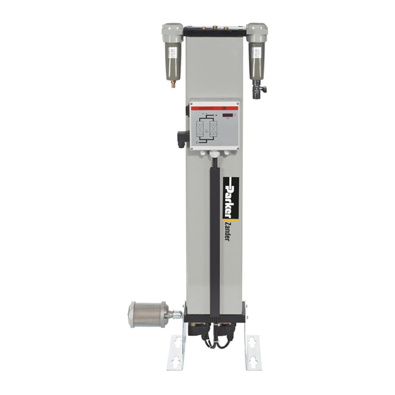
General information General information Manufacturer's details Name and address Details on the dryer Standard equipment Dryer, comprising 1 double-chamber hollow section vessel, fillied with drying agent 1 upstream filter 1 downstream filter Muffler Control system Associated documents ... -
Page 8: About These Operating Instructions
About these operating instructions About these operating instructions These operating instructions contain basic information on the safe useof the dryer. Characters and symbols used ► Work steps that you have to carry out in the sequence stated are marked by black triangles. -
Page 9: For Your Own Safety
For your own safety For your own safety The dryer has been built in accordance with the state of the art and the recognized technical safety regulations. Nevertheless, there is a risk of personal injury and damage to property when the dryer is used, if ... - Page 10 Signs and hazard areas on the dryer Hazard areas on the dryer Hazard caused by overpressure Hazard caused by electrical voltage Hazard caused by sudden air ejection during expansion Hazard caused by electrical voltage Front view Symbol in operating Hazard area instructions Warning against hazardous electrical voltage Different parts of the dryer carry electrical current.
-
Page 11: Intended Use Of The Dryer
For your own safety Risk of skidding When emptying and filling the hollow section vessels with drying agent, there is a risk of skidding caused by spilt drying agent. Intended use of the dryer The dryer is exclusively intended for drying compressed air. Depending on defined input conditions, it dries compressed air for industrial use. -
Page 12: Safety Notes On Specific Operating Phases
Safety notes on specific operating phases Safety notes on specific operating phases Transportation and siting During transportation all applicable national regulations for accident prevention must be complied with. Start-up Warning against sudden air ejection! During expansion the pressure is released suddenly through the muffler: ... - Page 13 For your own safety Monitor operation Warning against sudden air ejection! During expansion the pressure is released suddenly through the muffler: A loud cracking noise occurs which can injure your hearing. Particles carried in the air flow act like bullets and can injure your eyes or skin.
- Page 14 Safety notes on specific operating phases Only use replacement parts that are suitable for the relevant function and meet the technical requirements stipulated by the manufacturer. This is always the case, if you use original replacement parts only. Disassembly and disposal Hazard due to a sudden release of pressure! Never remove any parts of the dryer, or manipulate the same in any way, for as long as the plant is still pressurised! A sudden escape of pressure...
-
Page 15: Technical Product Description
Technical product description Technical product description Summary drawing Front view Regeneration gas return RV3–RV4 Dewpoint sensor (optional) (Option) Check valve plate (RV1–RV2) Differential pressure gauge Differential pressure gauge (K-MT 6-8) (only K-MT 6-8) Compressed air inlet Compressed air outlet Upstream filter Downstream filter Condensate trap Manual drain valve... - Page 16 Function description To this end, the two chambers alternate between different operating modes. Whilst in one vessel, compressed air is de-humidified (adsorption), in the other vessel the humid drying agent is prepared for another charge (regeneration). These two states, which run in parallel during compressed air preparation, are described below.
-
Page 17: Available Options
Technical product description Pressure build-up phase After dehumidification the pressure in the regenerated hollow section vessel is built up to operating pressure, so that the switchover from regeneration to adsorption can take place at operating pressure level. Pressure build-up Standby phase (only with the dewpoint-sensing control option) When in standby phase, the fully regenerated chamber is ready for absorption operation. - Page 18 Available options Signalling contacts of the control system & compressor synchronisation The control system is equipped with a digital input for the synchronised operation with a compressor. This feature allows for synchronised and thus efficient dryer operation with discontinuous compressor operation. Compressor synchronisation helps reduce energy costs, as the dryer can be operated independently of the compressor.
-
Page 19: Transportation, Installation And Storage
Transportation, installation and storage Transportation, installation and storage Danger due to incorrect transportation! The dryer must be transported by authorized and qualified specialist personnel only. During transportation all applicable national regulations for accident prevention must be complied with. Otherwise there is a risk of personal injury. -
Page 20: Transporting And Installing The Dryer
Transporting and installing the dryer Transporting and installing the dryer Requirements for the installation site The conditions at the installation site have a large influence on the functional capability of the dryer and the service life of the drying agent. In order to ensure a mode of operation, which is as continuous as possible, and low maintenance, the installation site must meet the following requirements: ... - Page 21 Transportation, installation and storage ► Secure the cardboard box or pallet on the lifting or forklift truck against sliding movements. ► Transport the dryer to its installation site. ► Remove the packaging of the dryer. K-MT 1-4: Dryer in a cardboard box K-MT 6-8: Dryer on transportation pallet Note the weight of the dryer! Depending on its size, the dryer may weigh up to approx.
-
Page 22: Storing The Dryer
Storing the dryer Storing the dryer If the dryer is to be stored for an extended period of time, the storage location must meet the following conditions: The dryer must not be stored in the open air. The storage room must be dry. ... -
Page 23: Installation
Installation Installation Only authorized and qualified specialist personnel may carry out work on pipes and electrical systems. As soon as the dryer has been set up at its installation location, you can install the compressed air infeed and outlet lines make the electrical connections. Preconditions for installation For a correct installation the following preconditions must be met on the part of the owner. -
Page 24: Connect Piping
Connect piping Connect piping In order to ensure that the dryer operates optimally, the dryer must be assembled into the compressed air system free of all stresses. ► Ensure before connection that all infeed and outfeed compressed air lines and valves are clean and undamaged. ►... -
Page 25: Installing The Electrical Connection
Installation Installing the electrical connection Warning against electrical voltage Only qualified specialist personnel may carry out work on the electrical system! Installing the supply cable The components of the dryer have been connected to the control cabinet at the factory. You only need to connect the control cabinet to the electrical supply cable. - Page 26 Installing the electrical connection Connecting the external signalling lines For compressor synchronisation The controller is fitted as standard with a digital input which makes the dryer regeneration dependent on operation of the compressor (switch S1 on the controller’s circuit board, see also figure below). If switch S1 is in the ON position, operation of the compressor and dryer regeneration run synchronously: When the compressor is stopped, the dryer regeneration also stops.
-
Page 27: Start-Up
Start-up Start-up Carry out all prescribed tests and checks. Before start-up, ensure that no tools or other foreign parts have been left lying in a part of the dryer where they might pose a hazard to the dryer being started up. -
Page 28: Setting Times Of The Operating Phases
Setting times of the operating phases Setting times of the operating phases In its standard version the dryer is delivered with a time-dependent control system. The phase sequence occurs in a fixed cycle. With the optional dewpoint-sensing control, the dryer can also be operated at variable cycles (depending on the dewpoint). - Page 29 Start-up Display panel The display panel at the switchbox is equipped with LEDs (light emitting diodes) and a digital display, indicating the operating status of the dryer: Display panel at the switchbox LED Power (1) LED is on when dryer is switched on. Flow diagram (2) The current operating phases of the dryer are indicated by means of 4 LEDs: Vessel B1:...
-
Page 30: Emergency Shutdown
Emergency shutdown Display Explanation Default display: The figure to the left indicates the current processing step; the figure to the right shows the remaining time in seconds. In this example, step 2 is being completed, whereby there are 215 seconds remaining. After 8000 operating hours, "SEr."... -
Page 31: Start Up Dryer
Start-up Start up dryer Warning against sudden air ejection! During expansion the pressure is released suddenly through the muffler: A loud cracking noise occurs which can injure your hearing. Particles carried in the air flow act like bullets and can injure your eyes or skin. - Page 32 Start up dryer ► Slowly open the compressed air inlet valve, installed by the owner, upstream of the dryer. ► Switch on dryer: to this end, set the ON/OFF switch to I. If the dryer is taken into operation for the first time, or after a change of drying agent, the following intermediate step is meaningful.
-
Page 33: Changing Cycle Mode
Start-up In the event of a fault In the event of an emergency or if a safety-relevant disruption occurs (e.g. escaping compressed air, defective component), immediately close the compressed air supply line and set the ON/OFF switch of the dryer to 0 in order to disconnect it from the power supply. - Page 34 Changing cycle mode Note: The compressor synchronisation controller is a higher-level controller than the pressure dew point controller. When both options are in place, the compressor synchronisation controller is treated as the prime controller. With dewpoint-sensing control (optional) Dryers equipped with dewpoint-sensing control operated in variable cycle mode, based on the measured dewpoint of the dried air at the compressed air outlet.
-
Page 35: Monitoring Dryer Operation
Monitoring dryer operation Monitoring dryer operation The dryer operates fully automatically. However, you should carry out the regular checks described in the Chapter Maintenance and repair of the dryer. Warning against sudden air ejection! During expansion the pressure is released suddenly through the muffler: ... -
Page 36: Shutdown And Restart Dryer
With dewpoint-sensing control (optional) Shutdown and restart dryer In the following cases, the dryer must be fully shut down and depressurised: In the event of an emergency or malfunction For maintenance work For dismantling Risk of injury from escaping compressed air! Never remove any parts of the dryer, or manipulate the same in any way, as long as the unit is pressurised! Suddenly escaping compressed air might cause serious injuries. -
Page 37: Emergency Shutdown
Shutdown and restart dryer Emergency shutdown To emergency shut-down the dryer heed to the following instructions: ► Close shut off valves upstream and downstream of the dryer (if applicable) ► Disconnect the electrical power supply (i.e. by switching the On/Off switch to ... -
Page 38: Restart
Restart Restart Depending on the fittings installed by the operator and the actual pressure conditions, the unit might have to be restarted at operating pressure. The following general rules apply: When switched off, the dryer is open in main flow direction. With the optional start-up device , the set minimum pressure must however be reached prior to restart. -
Page 39: Maintenance And Repair Of The Dryer
Maintenance and repair of the dryer Maintenance and repair of the dryer In order to allow maintenance work on the dryer to be carried out efficiently and without danger for maintenance personnel, you should comply with the following instructions. Notes on maintenance Warning! Maintenance tasks may be carried out only by authorized and qualified specialist personnel, and only with the plant in a switched off and... -
Page 40: Regular Maintenance Intervals
Regular maintenance intervals Regular maintenance intervals Note: If a chamber has been depressurised, e.g. after completion of the expansion phase, and the pressure remains above 0 bar, the chamber is pressurised by what is known as ram pressure. This might be due ... -
Page 41: Instructions For Use Of The Dongle
Maintenance and repair of the dryer Danger! There is a very considerable risk of personal injury, when carrying out work on the activated and pressurised dryer. Before commencing any maintenance tasks always shut down the dryer as described on page 37, ! Warning against electrical voltage! Only qualified specialist personnel may carry out work on the electrical system! -
Page 42: Maintenance Work To Be Completed Every 12 Months
Maintenance work to be completed every 12 months Clean dryer ► Remove any loose dust by means of a dry cloth, and, if required, also by means of a moist and well wrung cloth. ► Clean the surfaces with a moist well wrung cloth. Maintenance work to be completed every 12 months Check mufflers The dryer is either equipped with a standard muffler or a fine filter muffler. - Page 43 Maintenance and repair of the dryer Replace the element in the fine filter muffler ► Depressurise the dryer and shut it down (see page 37). ► Undo knurled screw on the lid cap and remove cap. ► Unscrew old filter element. Arrows on the element bottom mark the direction of rotation.
-
Page 44: Maintenance Work To Be Completed Every 24 Months
Maintenance work to be completed every 24 months Installing / dismantling pressure dewpoint sensor ► Loosen the screw at the adapter (1) and disconnect signal cable with the adapter and seal. ► Remove dewpoint sensor from the sensor cell (3) by turning the nut (2). ►... -
Page 45: Maintenance Work To Be Completed Every 48 Months
Maintenance and repair of the dryer Maintenance work to be completed every 48 months Replace check valves Check valves are wear parts and must thus be replaced every 48 months, even if no damage is visible. ► Release pressure from dryer and shut down the unit (see page 37). ►... - Page 46 Maintenance work to be completed every 48 months Replace solenoid valves Solenoid valves are wear parts and must thus be replaced every 48 months, even if no damage is visible. ► Release pressure from dryer and shut down the unit (see page 37). Preparation for the replacement of all four solenoid valves: ►...
- Page 47 Maintenance and repair of the dryer Risk of falls! The dryer must not be misused as a climbing aid! The components have not been designed for such loads and could fracture. Only use approved climbing aids when disassembling the check valve plate.
- Page 48 Maintenance work to be completed every 48 months Risk of skidding! If drying agent has been spilt on the floor, there is a risk of skidding caused by the drying agent beads. Therefore, spilt drying agent must always be taken up immediately. Remove used drying agent ►...
- Page 49 Maintenance and repair of the dryer Fill with new drying agent and remount check valve plate Risk of falls! The dryer must not be misused as a climbing aid. The components have not been designed for such loads and could fracture. Only use approved climbing aids when filling the chambers.
-
Page 50: Identify And Eliminate Faults
Summary of faults Identify and eliminate faults The following table provides information on what designatory abbreviations are to be used for the various components. These designations are also found in the technical ocumentation. Abbreviation Component Differential pressure gauge (only K-MT 6-8) V1–V2 (Y2–Y1) Main valves (solenoid valves) V3–V4 (Y3–Y4) Expansion valves (solenoid valves) RV1–RV2... - Page 51 Identify and eliminate faults Fault Possible cause Remedy No expansion Solenoid valve Y3/Y4 cannot be Check supply voltage, cable, contacts opened. and solenoid; replace, if necessary. Solenoid valve Y3/Y4 cannot be opened Check supply voltage. properly Check spring and solenoid; replace, if ...
-
Page 52: Index
Index Documentation, technical ........54 Dongle use ..............41 Abbreviation Dryer components ............50 maintenance interval ........... 40 Address, manufacturer ..........7 Drying agent Adsorption, explanation ........... 16 charging .............. 18 Air ejection, sudden ..........10 handling ............... 11 maintenance interval ........... 40 service life ............ - Page 53 Index Muffler ..............42 Replacement parts ..........14, 39 sensor ..............43 Risk of skidding ............11 solenoid valves ............ 46 Maintenance contract ..........39 Maintenance, danger warnings ........ 41 Safety notes ............... 9 Misuse ..............11 general ..............11 Misuse, suspected ...........
-
Page 54: Annex With Technical Documentation
Annex with technical documentation This annex comprises the following information and technical documentation: Technical data Replacement and wear parts list Logic control diagram Flow diagram Dimensional drawing K-MT1-8_EN_08—2014... -
Page 55: Technical Data
Annex with technical documentation Technical data Operating Range Site Selection frost-free indoor installation in a non-hazardous environment Ambient temperature 1,5 to 50 °C (24,7 to 122 °F) Compressed air inlet temperature 20 to 50 °C (68 to 122 °F) Max. operating overpressure 16 bar Min. -
Page 56: Replacement And Wear Parts List
Replacement and wear parts list Replacement and wear parts list Note: When exchange or replacement parts are ordered, always state the dryer type and the build no. of the dryer. These data are found on the type plate. Service-kits For model Maintenance Mains Order-ID. -
Page 57: Logic Control Diagram
Annex with technical documentation Logic control diagram Adsorption in B1 and regeneration in B2 K-MT1-8_EN_08—2014... - Page 58 Logic control diagram Regeneration in B1 and adsorption in B2 K-MT1-8_EN_08—2014...
-
Page 59: Flow Diagram
Annex with technical documentation Flow diagram Pos. Designation Pos. Designation Check valve plate Control unit 10.101 Seal Control system 10.102 Perforated plate Upstream filter 10.107 Demister, left Downstream filter 10.108 Demister, right Muffler 10.109 Left perforated plate Optional devices: 10.110 Conical pressure spring Start-up device 10.111... -
Page 60: Dimensional Drawing
Dimensional drawing Dimensional drawing Installation on floor K-MT1-8_EN_08—2014... - Page 61 Annex with technical documentation Installation on wall Dimensions [mm] BSP-P/ Weight Type [kg] K-MT 1 1/4" 11,5 K-MT 2 1/4" 15,5 1/4" 20,0 K-MT 3 K-MT 4 1/4" 1075 1040 1051 1017 25,0 K-MT 6 1/2" 1203 1135 1097 1029 48,0 K-MT 7 1/2"...
Need help?
Do you have a question about the K-MT 1-8 and is the answer not in the manual?
Questions and answers