Table of Contents
Advertisement
Advertisement
Table of Contents

Related Manuals for Parker Airtek MSC Series


Summary of Contents for Parker Airtek MSC Series
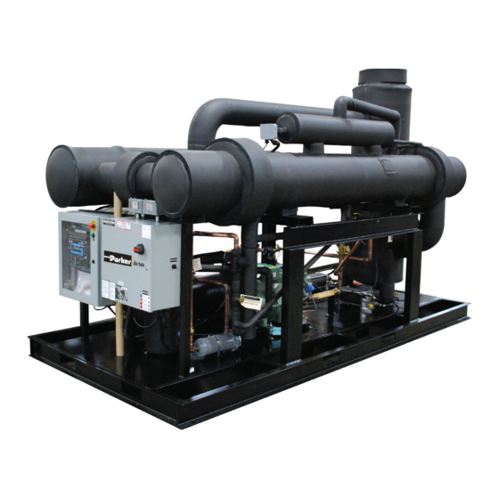
- Page 1 MSC Refrigerated Air Dryer Models MSC4000 to MSC15000 User Guide...
- Page 2 No effort has been spared to provide a comprehensive instruction manual for the use of the Parker Dryer. Information is given not only for the user, but also for the technical personnel who may repair the dryer in the event that this is ever necessary. It is recommended that all who will have responsibility for the dryer carefully read all sections of this manual before commencing with the installation.
-
Page 3: Table Of Contents
MSC4000 - MSC15000 USER GUIDE Contents Pre-Installation Inspection, Handling and Setup Dryer Installation Location of Dryer Outdoor Installation (Sheltered) Airline Plumbing Electrical Connections Principle of Operation Start Up Procedure Preliminary Checks Refrigeration Service Valves Starting the Dryer Start Up Checklist Comments / Recommendations / Observations Control Center MRD Drains... -
Page 4: Pre-Installation
MSC4000 - MSC15000 USER GUIDE Pre-Installation Inspection, Handling and Setup Inspect the dryer carefully upon arrival and note any damage on the freight bill. File a notice of concealed damage if: (1) there are any dents in the cabinet; (2) the air and drain pipes are not straight;... -
Page 5: Airline Plumbing
MSC4000 - MSC15000 USER GUIDE Airline Plumbing All connections are made to the outside of the cabinet as follows: • Plumbing must be supported independently of the dryer. • If vibration is present, flexible metal hoses must be installed to prevent it from being transmitted to the dryer. -
Page 6: Principle Of Operation
MSC4000 - MSC15000 USER GUIDE Principle of Operation The dryer is designed to operate automatically and continuously from no load to full load without freeze up. Air System The major air system components are the air-to-air PRECOOLER / REHEATER, the EVAPORATOR, and the MECHANICAL SEPARATOR. -
Page 7: Start Up Procedure
MSC4000 - MSC15000 USER GUIDE Start Up Procedure Preliminary Checks Before starting the dryer, verify that the compressed air valves are closed so there is no airflow through the dryer, the dryer supply voltage is correct, and there is sufficient water supply to the unit (water cooled). - Page 8 MSC4000 - MSC15000 USER GUIDE • SLOWLY close the air bypass valve until the dryer is under an air load. Note: Fast opening of air valves could damage the heat exchangers. At this time, complete the following start up form. Note: The refrigerant compressor may require additional oil added.
-
Page 9: Start Up Checklist
MSC4000 - MSC15000 USER GUIDE Start Up Checklist... -
Page 10: Comments / Recommendations / Observations
MSC4000 - MSC15000 USER GUIDE Comments / Recommendations / Observations Comments / Recommendations / Observations Completed By: (Print) ___________________________ Cert.# (REQUIRED)______________________________ Signature: _____________________________________... -
Page 11: Control Center
MSC4000 - MSC15000 USER GUIDE Control Center PREFACE: This document is intended to make familiar, the Control Center functionality. The “manual”, can serve as a handy guide to quickly move through the operations of the dryer it is controlling. It is not intended to replace the more comprehensive, specific “dryer manual”... - Page 12 MSC4000 - MSC15000 USER GUIDE FLOW RANGE SETTINGS • DRAINS SETUP MENU (“I” Series Menus)----------------------------------------------[ 12 ] #1 DEMAND or TIMED OPERATIONS #1 INTERVAL (Timed) #1 DURATION #1 AUTOTEST #2 DEMAND or TIMED OPERATIONS #2 INTERVAL (Timed) #2 DURATION #2 AUTOTEST •...
- Page 13 MSC4000 - MSC15000 USER GUIDE 1. Up Arrow Scroll Menu Up or Increment Value 2. Down Arrow Scroll Menu Down or Decrement Value 3. Set Enter Menu Selection, Enter Program Mode or Save to Memory 4. Reset Alarm Back-up Menu Level or Clear ‘Resetable’ Alarm 5.
- Page 14 MSC4000 - MSC15000 USER GUIDE STARTUP NULL SCREEN------------------------------------------------------------------ Upon initialization, the display shows the “type” of dryer the Control Center is configured to control. An example: Company REFRIG DRYER (R404A) S/N B00001 V2.12IR4 This is a fixed configuration. Once assigned to a dryer: the Control Center will never be changed to any of the other configurations.
- Page 15 MSC4000 - MSC15000 USER GUIDE 2. The second line is the “mode” line. This line will indicate the dryers operations: • SYSTEM INACTIVE (NULL), • EMERGENCY STOP, • AUTO RUN MODE • LOAD/UN-LOAD MODE, • THERMAL BANK MODE, • SYSTEM OFF, and •...
- Page 16 MSC4000 - MSC15000 USER GUIDE ALARM SHUT DOWN When a “shut-down” alarm occurs, the dryer will “stop operating and will require a Manual Reset (see VIEW ALARMS section). Once the alarm has been reset and if the alarm condition has been cleared, the system may be re-started.
- Page 17 MSC4000 - MSC15000 USER GUIDE ALARM E3: HI SUPERHEAT DAYS SINCE LAST: --- ALARM OUT: YES ALARM E4: DRYER OVERLOAD DAYS SINCE LAST: --- ALARM OUT: YES ALARM E5: LOW PRESSURE DAYS SINCE LAST: --- ALARM OUT: YES J8 ALARM LOW REFRIGERANT/OIL PRESSURE E6: LOW PRESSURE NOTE: IF MULTIPLE COMPRESSORS –...
- Page 18 MSC4000 - MSC15000 USER GUIDE E. DISPLAY SENSOR VALUES (“K” Series Menus)--------------------------------------------------- The DISPLAY VALUE pushbutton is a quick way to view groupings of sensor values. The UP/DOWN arrows will scroll through the 7 possible groups of the “K” series screen. Superheat 12ºF T4: Refrig 130ºF...
- Page 19 MSC4000 - MSC15000 USER GUIDE 1. DEW POINT MENU----------------------------------------------------------------------------------- DEW POINT MENU Press SET to Select DEW POINT – The dryer will attempt to deliver a dew point relative to the DEW POINT SET POINT value. The range for this setting can be selected between 34ºF (1ºC) to 50ºF (10ºC). When the dew point indicated is at the set point value or less, the panel LCD display will give a message: POWERSAVE ACTIVE DEW POINT Value:...
- Page 20 MSC4000 - MSC15000 USER GUIDE CALIBRATION MENU ALARM REPORTING ALARM #1 HIGH DEW POINT RELAY PAGER REMOTE ALARM #2 FLOW/AUX RELAY PAGER REMOTE ALARM #3 DP PROBE FAULT RELAY PAGER REMOTE ALARM #4 MOTOR FAULT RELAY PAGER REMOTE ALARM #1 E3: HI SUPERHEAT RELAY PAGER...
- Page 21 MSC4000 - MSC15000 USER GUIDE ALARM #13 W4: HIGH AIR-IN ºF ALARM #14 W5: HIGH AMBIENT/H RELAY PAGER REMOTE ALARM #15 W5: HIGH AMBIENT/H RELAY PAGER REMOTE ALARM #16 MODEM FAULT RELAY PAGER REMOTE CALIBRATION MENU Each of the transducers in the system has their ranges set in the “H” series screens. It is important that the value indicated in the screens match the maximum range of the transducer span.
- Page 22 MSC4000 - MSC15000 USER GUIDE Suction Pressure Actual: 0 psi Offset [0 psi] Fullscale 600 psi Suction Pressure Actual: 0 psi Offset 0 psi Fullscale [600 psi] Flow Actual: OPEN Offset [0 scfm] Fullscale 100 scfm Flow Actual: OPEN Offset 0 scfm Fullscale [100 scfm]...
- Page 23 MSC4000 - MSC15000 USER GUIDE I2 Drain #1 Type DEMAND Interval (m:s) [10]:00 Duration 2 Sec I3 Drain #1 Type DEMAND Interval (m:s) [10]:[00] Duration 2 Sec I4 Drain #1 Type DEMAND Interval (m:s) 10:00 [2] Sec Duration I5 Drain #1 [0:05] On Delay (m:s) Auto Test (h:m)
- Page 24 MSC4000 - MSC15000 USER GUIDE 3. SENSOR SETTINGS------------------------------------------------------------------------------------------- SENSOR SETTINGS Press SET to select P1 LOW INLET Value: 100 psi Alarm Set: 50 psi P1 HIGH INLET Value: 100 psi Alarm Set: 101 psi P4 DISCHARGE Value: 240 psi Alarm Set: 350 psi P5 SUCTION Value:...
- Page 25 MSC4000 - MSC15000 USER GUIDE AUX #1 ALARM Low Alarm: High Alarm: [00.05] Delay (m:s): AUX #1 SENSOR Enabled: [NO] Value: AUX #2 ALARM Low Alarm: High Alarm: Delay (m:s): 00.05 AUX #2 ALARM Low Alarm: High Alarm: [100] Delay (m:s): 00.05 AUX #2 ALARM Low Alarm:...
- Page 26 MSC4000 - MSC15000 USER GUIDE 5. VIEW ALARMS----------------------------------------------------------------------------------- VIEW ACTIVE ALARMS Press SET to select ACTIVE ALARMS Press UP/DOWN to View active alarms Press RESET to EXIT ACTIVE ALARMS HIGH DEW POINT (Self-Resetting) Press RESET to EXIT A3a SYSTEM SHUTDOWN - Requires a manual reset. ACTIVE ALARMS LOW FLOW (Self-Resetting)
- Page 27 MSC4000 - MSC15000 USER GUIDE ACTIVE ALARMS E5: DRYER OVERLOAD Press RESET to Clear ACTIVE ALARMS E6: LOW REFRIG / OIL PSI Press RESET to Clear ACTIVE ALARMS E7: HIGH REFRIG PSI Press RESET to Clear ACTIVE ALARMS W1: LOW AIR-IN PSI (Self Resetting) Press RESET to Exit ACTIVE ALARMS...
- Page 28 MSC4000 - MSC15000 USER GUIDE ACTIVE ALARMS A16 Drain Requires a manual reset. MODEM FAILURE Press RESET to Clear ACTIVE ALARMS No Active Alarms Press RESET to EXIT COMPRESSOR MENU Press SET to Select Auto-Sequence “Time” can be selected between 1 & 72 hours. COMPR #1 [ENABLED] NOTE: When set to “TEST”, units will sequence STANDBY...
-
Page 29: Mrd Drains
MSC4000 - MSC15000 USER GUIDE MRD Drains The MRD is designed to reliably discharge condensate while preventing the loss of valuable compressed air. Rising condensate in the sump actuates a mechanical float switch operating the drain valve. The drain valve remains open until the sump is empty. The MRD only discharges condensate. No compressed air is wasted. -
Page 30: Routine Maintenance
MSC4000 - MSC15000 USER GUIDE Routine Maintenance The maintenance chart below indicates the components that should be checked while performing routine maintenance on the dryer. The chart also indicates how often a specific check should be done. DESCRIPTION OF SERVICE REQUIRED SERVICE RECOMMENDED EVERY: COMPONENT OPERATION... -
Page 31: Routine Maintenance
MSC4000 - MSC15000 USER GUIDE Routine Maintenance This section covers the various components that require periodic maintenance and/or replacement. Coalescing Filter Element The coalescing filter element should be check Biannually. On units with the standard control panel, check the pressure drop across the unit by using air pressure gauges upstream and downstream of the dryer using the closest possible gauges to the dryer. - Page 32 MSC4000 - MSC15000 USER GUIDE The refrigeration pressure switches should be checked monthly to ensure that they are adjusted to the proper settings. Please refer to the applicable electrical drawings for your unit. Compressor Oil Level The oil level in the compressor should be checked daily. The refrigeration system should never need oil unless the system is leaking or has been recently repaired.
-
Page 33: For The Refrigeration Technician
This section is a list of hints and instructions for the skilled serviceman and relating specifically to the Parker Airtek Dual Mode refrigeration system. Recharging Dryer - Refrigerant, Oil and Dryers Refer to the dryer information tag on the front of the unit for the approximate charge needed for each unit. The relatively large charge is needed because of the flooded-shell evaporators. -
Page 34: Refrigerant Control Valves
Unloader solenoids operate with greater differentials and so are more likely to fail. Parker Airtek uses valves with a rated life of more than two million operations. When they finally wear out, the usual symptom is failure to close. The valves can usually be restored by installing a diaphragm repair kit available from Parker Airtek or the valve’s local distributor. -
Page 35: Factory Assistance
A short call may save a long troubleshooting experience. Instructions for Ordering Parts All parts orders should be placed with your Parker Airtek Dealer. Should you not know the dealer in your area, contact Parker-FAF. When ordering parts, specify dryer model and serial numbers to insure receiving proper parts (see nameplate on unit). -
Page 36: Diagnostic Codes
MSC4000 - MSC15000 USER GUIDE Diagnostic Codes Diagnostic Code “E1” Shutdown on Open Dew Point Circuit The dew point sensing circuit is devised of three parts. The dew point probe, cable and digital control board. The combination of these parts measures the air temperature leaving the evaporator. -
Page 37: Diagnostic Code "E3" Shutdown On High Super Heat
MSC4000 - MSC15000 USER GUIDE Should the display on the digital control board change from a “E2” to a “E1”, the short is in the dew point probe. Replace it. If the display continues to show a “E2” disconnect power to the unit and locate the connection between the cable and digital control board, and disconnect it. -
Page 38: Diagnostic Code "E4" Shutdown On Freeze Protection
MSC4000 - MSC15000 USER GUIDE D) Expansion Valve Stuck Closed Test by applying heat (hair dryer) to TXV sensing bulb located just after the flood level control for about 30-45 seconds. This should cause the unit to flood back and lower the super heat. To check this, take a temperature reading on the suction accumulator, it should be extremely cold, if it is not, your expansion valve is stuck closed. - Page 39 MSC4000 - MSC15000 USER GUIDE If you have determined that the valve is not getting energized electrically, then the valve may have malfunctioned mechanically. Determining this is relatively easy. When the dryer is refrigerating and the Power Saver Active light is off we know that the unloader solenoid should be closed.
-
Page 40: Diagnostic Code "E6" Shutdown On Low Suction Psi
MSC4000 - MSC15000 USER GUIDE Diagnostic Code “E6” Shutdown on Low Suction PSI If the suction pressure of the refrigeration system drops 20 psi (1.4 bar g) or lower it will break contact through the low-pressure switch. This in turn breaks power to the refrigerant compressor for protection. -
Page 41: Diagnostic Code "E7" Shutdown On High Head Psi
MSC4000 - MSC15000 USER GUIDE a) You need to first check the coil of the liquid line valve to ensure that it is functioning. The easiest way to verify if the coil is energized is to take a screwdriver and touch it to the screw or post on the top of the coil. - Page 42 MSC4000 - MSC15000 USER GUIDE High Ambient - Take a temperature reading at the condenser, anything over 100ºF (38ºC) is no good. High Compressed Air Flow - Compare HP or CFM and run time to the rating of the dryer. High Inlet Compressed Air Temperature - To test take a temperature reading with an infrared temperature gun on the inlet pipe.
-
Page 43: Diagnostic Code "E9" Drain Shutdown
MSC4000 - MSC15000 USER GUIDE You need to first check the coil of the liquid line valve to ensure that it is functioning. The easiest way to verify if the coil is energized is to take a screwdriver or a piece of metal and touch it to the screw or post on the top metal to the screw or post. -
Page 44: Maintenance Charts
MSC4000 - MSC15000 USER GUIDE Maintenance Charts MAINTENANCE LOG SERVICE PERFORMED DATE PARTS REPLACED INITIALS... -
Page 45: Warranty And Product Registration
MSC4000 - MSC15000 USER GUIDE Warranty and Product Registration... -
Page 46: Drawings & Spare Parts
MSC4000 - MSC15000 USER GUIDE Drawings & Spare Parts... - Page 47 +44 (0) 191 410 5121 www.parker.com/watermakers www.parker.com/africa www.parker.com/processfiltration © 2011 Parker Hannifin Corporation. Product names are trademarks or registered trademarks of their respective companies. Catalog: MSC4000 - 15000 Series User Guide Rev 001 NA 1/2013 Parker Hannifin Corporation Industrial Gas Filtration and Generation Division...
Need help?
Do you have a question about the Airtek MSC Series and is the answer not in the manual?
Questions and answers