
Related Manuals for AkitikA GT-104


Summary of Contents for AkitikA GT-104
- Page 1 GT-104 STEREO AUDIO POWER AMPLIFIER ASSEMBLY MANUAL © 2022 AkitikA LLC All rights reserved Revision 2p02 November 3, 2022 Page 1 of 56...
-
Page 2: Table Of Contents
Table of Contents Table of Contents ........................ 2 Table of Figures ........................3 Section 1: About This Manual .................... 5 Who Should Attempt this Project? ................. 5 Tools You’ll Need......................5 Project Overview ......................5 Important Safety Notes ....................6 About Components ...................... -
Page 3: Table Of Figures
Power-On Tests ......................45 Set the Bias Current ....................46 Install the Top ......................47 Section 6: Using the GT-104 .................... 47 Section 7: Specifications and Schematics ................. 47 Section 8: Theory of Operation ..................51 Power Supply ........................ 51 Bulk DC Supply ...................... - Page 4 Figure 8-Remember to solder Q5's leads ................14 Figure 9-Assembled Power supply mounted on heat sink ..........14 Figure 10-Empty the amplifier components into a soup bowl .......... 15 Figure 11-Close-up of bare Amplifier PCB ..............15 Figure 12-Note flat side of LED package sits under number 1 and 2 in LED1 and LED2 ............................
-
Page 5: Section 1: About This Manual
Section 1: About This Manual This manual gives the information you need to build Akitika LLC’s GT-104 Stereo Power Amplifier. The GT-104 delivers a total of 120 Watts in the form of 60 Watts per channel into 4-Ohm loudspeakers. Who Should Attempt this Project? You can build this kit if you can: 1. -
Page 6: Important Safety Notes
63/37 Rosin Core solder. Akitika LLC’s liability shall in no event exceed the cost paid to Akitika LLC for the kit. https://en.wikibooks.org/wiki/Practical_Electronics/Soldering has entries for both 60/40 and 63/37 solder blends. -
Page 7: Section 2: Building The Power Supply Pcb
Section 2: Building the Power Supply PCB This section details the process of building the power supply circuit board. We start with an overview on this page. The specifics you need to start building begin on the next page. The bare power supply PCB is shown in Figure 1. Figure 1-Component side of power supply PCB before loading Begin by carefully emptying the contents of the envelope marked “GT-102 PSU Module”... -
Page 8: Figure 2-Installing Resistors
Color Code column and the resistor from left to right. The GT-104 is based on parts from the GT-102, with the addition of a number of parts that are unique to the GT-104. You will therefore see that there are two power supply envelopes. -
Page 9: Install The Diodes
Install the Diodes Now install the diodes. Be careful to observe the polarity markings on the diodes. You’ll notice that one end of the diodes has a band. That band indicates the cathode of the diode. Match the banded end of the diode with the banded end of the silk screen. The following information should help you identify the diodes. -
Page 10: Install The Last Resistor
Designation Type, Package Description Done? () BZX55B20, DO-35 20 Volt 2% zener diode BZX55B33, DO-35 33 Volt 2% zener diode BZX79-B10, DO-35 10 Volt 2% zener diode 1N4148, DO-35 0.2 A, 100 PIV, switching diode 1N4148, DO-35 0.2 A, 100 PIV, switching diode 1N4148, DO-35 0.2 A, 100 PIV, switching... -
Page 11: Install The Small Capacitors
2 Watt, 5% resistor Designation Value Marking Done? () Install the Small Capacitors Now install the small capacitors: C1, C2, and C3 are polarized, showing a minus sign (-) on the negative end of the capacitor. Make sure that the minus sign faces away from the plus sign (+) marked on the silk screen for each of the capacitors. -
Page 12: Install The Big Capacitors
2N3904, TO-92 60 V NPN bipolar transistor 2N3904, TO-92 60 V NPN bipolar transistor 2N5401, TO-92 150 V PNP bipolar transistor 2N5401, TO-92 150 V PNP bipolar transistor Don’t use too much solder on the transistor leads. This is one place where the spacing is close enough that extra solder might cause short circuit between two leads on a given transistor. -
Page 13: Figure 5-Note The Rounded Brackets Used For The Power Supply Heatsink And Pcb
Figure 5-Note the rounded brackets used for the power supply heatsink and PCB 1. Use two 6-32x3/8” screws to fasten a pair of mounting brackets to the heat sink, placing the screw through the 9/64” clearance hole in the bracket. Note that one hole in the mounting bracket is a 9/64”... -
Page 14: Figure 8-Remember To Solder Q5'S Leads
Figure 8-Remember to solder Q5's leads 5. Line up the PCB, brackets, and Q5 so everything is square and fits comfortably, then tighten the 5 screws: a. 2 that hold the brackets to the PCB b. 2 that hold the brackets to the heatsink c. -
Page 15: Section 3: Assembling The Amplifier Circuit Boards
Section 3: Assembling the Amplifier Circuit Boards This section details the process of building the amplifier module circuit boards. We start with an overview on this page. Begin by carefully emptying the contents of one of the envelopes marked “GT-102-104 Amp Delta Kit” and one “GT-102 Amplifier Module” into a broad soup bowl, as shown in Figure 10. -
Page 16: Install The Resistors
(higher wattage) resistors. Important Notes: 1. The GT-104 is a dual channel amplifier. You will build two identical channels. We’ve provided two Done columns, Done1 for the first channel you build, and Done2 for the second channel. We recommend that you build the channels one at a time, completing the first channel, then returning to this point to build the second channel. - Page 17 Brown, Black, Black, Brown, Brown Brown, Black, Black, Brown, Brown Brown, Black, Black, Brown, Brown Brown, Black, Black, Brown, Brown Brown, Black, Black, Brown, Brown Brown, Black, Black, Brown, Brown Brown, Black, Black, Brown, Brown Brown, Green, Black, Brown, Brown Brown, Green, Black, Brown, Brown 8K06 Gray, Black, Blue, Brown, Brown...
-
Page 18: The Following Are 0.1% Resistors
The following are 0.1% resistors Designation Value Color Code Done 1 Done2 Brown, Black, Black, Brown, Violet; 0.1% In some kits, the resistor may have numbers: 1K 0.1% on a brown body 20K, Red, Black, Black, Red, Violet 0.1% In some kits, the resistor may have numbers: 20K 0.1% on a brown body. -
Page 19: Small Capacitors
Designation Value Package Done1 Done2 LED1 LED, green T1 LED package LED2 LED, green T1 LED package Figure 12-Note flat side of LED package sits under number 1 and 2 in LED1 and LED2 Small Capacitors Designation Value Marking, Type Done Done 0.1µF@100V... -
Page 20: Transistors
0.1@2W, 5% Written on body 0.1@2W, 5% Written on body 10@2W, 5% Brown, Black, Black, Gold. 10@2W, 5% Brown, Black, Black, Gold. 10@2W, 5% Brown, Black, Black, Gold 2K2@1W, 5% Red, Red, Red, Gold 1K@2W, 5% Brown, Black, Red, Gold Transistors Install the small signal transistors. -
Page 21: Install T8 And T9
Install the voltage regulators. They are packaged in a TO-92 package that looks just like the transistors that were previously installed. Make sure to look for the identifying markings. Orient the regulators so their body shape matches the silk-screen outline. Leave the top of the regulator about ½”... -
Page 22: Install The Polarized Capacitors
Figure 15-Installing T8 and T9 on the circuit board Leave about 0.1-0.2” between the bottom of the heatsink and the tops of the ¼ Watt metal film resistors. Hint: Start by soldering only the center leg. This makes it easy to adjust the transistor’s height. -
Page 23: Install Relay K1
2. Strip back 3/8” of insulation from both ends of the wire. Be careful not to nick the conductors. 3. From the component side, place one stripped end of the wire into the L1A terminal. Bend it on the solder side to retain it, but don’t solder it yet. Route it around the output capacitor as shown in Figure 16. -
Page 24: Install Bias Pot
2. Solder one corner pin. Make sure the relay sits flat on the board. If it doesn’t, push it in while you re-heat that pin. 3. Solder the opposite corner pin and check again that all the pins have come through the PCB, and that the relay body rests flat on the PCB. -
Page 25: Install The Power Mosfets And Mount The Amplifier Board To The Heatsink
2. There are no solder bridges between pads which should be isolated. Solder bridges may stop the amplifier from working correctly. Install the Power MOSFETS and Mount the Amplifier Board to the Heatsink You’ll repeat the process described in this section two times, once for each amplifier module. -
Page 26: Figure 20-Spread A Thin Film Of Thermal Compound On Q4 (Irfp9140), But Keep It Off The
3. Place a dab of thermal compound on the back of the Q4, which is a IRFP9140 power MOSFET and spread it into a thin film, being careful to keep the leads clean. This step uses just a small amount of the thermal compound in the squeeze tube. -
Page 27: Figure 21-Threading The Screwdriver To Q4'S Mounting Screw
Figure 21-threading the screwdriver to Q4’s mounting screw 7. Inspect your soldering from both sides, making sure that there are no solder bridges between the leads of Q4. 8. Locate Q5, an IRFP140, the insulator, and the 6-32x1/2” sems screw used to mount Q5 to the heat sink. -
Page 28: Figure 23-First Amplifier Channel Completed And Installed
you push Q19’s body to lay flat on Q5. The idea is that we want Q19 to be a good sensor of Q5’s temperature. Tighten the mounting screw that holds Q19 and Q5 to the heatsink. Solder Q19’s leads to the PCB. You have just completed the first of two amplifier modules. -
Page 29: Section 4: Wiring It All Together
Note: The X1, X2, VCC, PGND1 and PGND2 eyelets will remain open until a later assembly step. The overall mechanical parts of the GT-102 and GT-104 are quite similar, so the wiring kit may say either GT-102 or GT-104. Page 29 of 56... -
Page 30: Attach The Amplifier Module Power Wires
Attach the Amplifier Module Power Wires Figure 26-Right and Left Channel Designations Attaching LEFT Module Power Wires 1. For the module designated as LEFT (see Figure 26), cut a 9” overall length of Red/Black 18 AWG zip cord. 2. Separate the Red and Black wires about 1 inch at each end. 3. -
Page 31: Prepare Input Shielded Cables
Prepare Input Shielded Cables 1. Prepare a 5 1/2” length of shielded cable for the LEFT channel input per the directions that begin on Page 55. Prepare both ends per those directions. Twist and tin the wires at one end of the cable. Leave the other end tightly twisted, but un-tinned. -
Page 32: Install The Feet
You’ll get the best results if you’ve tinned the stripped ends of the wires before you crimp them into the solder lugs. Once all the connections are crimped in place on a given lug, solder the lugs using enough heat to make the solder flow. When you do this, the wires should be straight, as the heat will encourage the insulation to back off a bent wire. -
Page 33: Ac Power Wiring
Designation Value Marking Done 24.9 Red, Yellow, White, Gold, Brown 10 nF 10nJ100 GBPC3506W 1. Locate the green 18 AWG stranded wire with a FASTON terminal installed on one end. Cut it to an overall length of 14”, measured from the far-end of the FASTON. -
Page 34: Figure 34-Power Wiring With Iec Connector Installed Into Chassis
3. Starting outside the chassis, insert the black and white wires (already connected to the IEC power connector) into the hole in the back-right corner of the chassis as shown in Figure 34. Make sure that the writing on the power connector is right side up! Push until it clicks in place. -
Page 35: Install The Rca Jacks And Speaker Binding Posts
9. Starting with the switch outside the chassis, push the FASTONs on the bottom switch terminals as indicated in Figure 35. The black or white wire may be on either side of the switch, so long as they both attach to the bottom row of contacts. Figure 35-Installing power wires on the switch 10. -
Page 36: Install The Speaker Binding Posts
in Figure 36. Use the right channel shielded cable and ground harness that you previously built. 1. Insert the RCA jack and the two insulating washers and ground lug as shown in Figure 36. The ground lug already has two black wires attached. Tighten the mounting nut. -
Page 37: Amplifier Channels Final Wiring
binding post nuts and tighten it with a 5/16” nut-driver. The free end of the white wire will be connected to the left channel amplifier OUT in a later step. Right Speaker Binding Post 1. Slip the #10 lug from the right channel ground harness (black 18 AWG wire) over the black binding post stud. -
Page 38: Installing Amplifier Modules Into The Chassis
1. Identify the 18 AWG white wire that connects to the LEFT channel red binding post. Twist the conductor strands tightly, and insert the wire into the LEFT Channel OUT eyelet from the solder side of the board. Solder it on the component side of the board. -
Page 39: Figure 39-Wiring Toroidal Transformer For 120 Volt Operation
Figure 39-Wiring toroidal transformer for 120 Volt operation 1. Cut a 2.5” length of 3/16” diameter heat-shrink tubing. Slide it over the blue and violet leads of the power transformer. Slide it as far from the cut ends of the wire as possible. -
Page 40: Transformer Installation
Figure 40-Western Union splice has diameter less than the insulated wires and no sharp points 9. Cut the red and orange transformer wires to a length of about 2”. 10. Remove 3/8” of insulation from the red and orange transformer wires. 11. -
Page 41: Testing The Power Supply
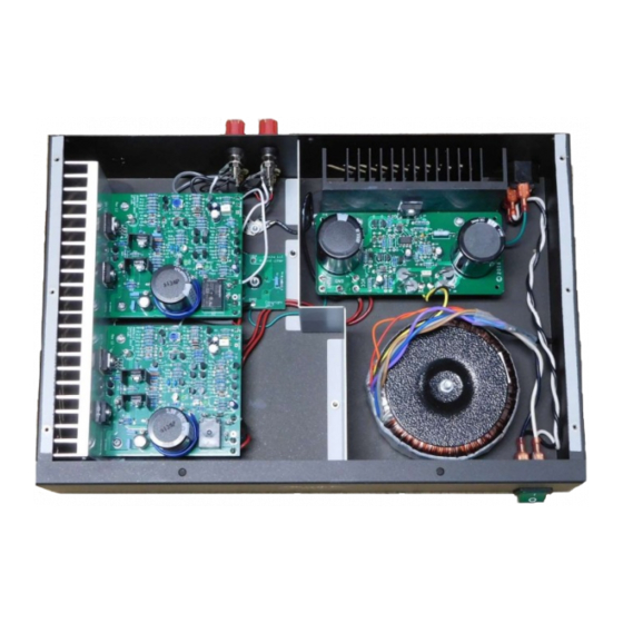
4. Dress the black-white twisted pair that goes from the switch to the power entrance connector into the crease along the right side of the chassis. 5. Dress the transformer primary leads as shown on the front cover of this manual. 6. -
Page 42: Final Amplifier Wiring
5. Locate the supplied IEC power cord. Make sure it is NOT connected to the AC wall socket yet. Connect one end to the IEC power connector on the chassis. 6. Standing well away from the amplifier, connect the plug into the AC wall socket. Keeping one hand in your pocket, use the other hand to turn on the power switch. -
Page 43: Install The Wall And Fasten The Transformer Down
2. This step is optional, but it is recommended if you listen for long periods at high levels. Spread a thin film of thermal compound on the 3/8” wide ridge of the heatsink (the side with two 6/32 mounting holes). Note: the transformer is not yet fastened in place. -
Page 44: Figure 44-Routing The Wires Thru The Slots In The Wall
Figure 44-Routing the wires thru the slots in the wall Refer to Figure 44 to see how the power and ground wires route through the slots in the wall: 1. Route the power supply ground wire through the back hole in the wall. 2. -
Page 45: Visual Inspection
5. Fasten the wall to the bottom of the chassis using two 6-32x3/8” black screws installed from the bottom of the chassis and into the fasteners on the wall. Make sure that the wires pass easily through the slots in the wall, and aren’t being pinched. -
Page 46: Set The Bias Current
resistor on the output. The voltage will typically decline with time. When a speaker is present, the DC voltage will be less than 10 millivolts. 2. Turn the power off. Set the Bias Current At this step, you will set the bias pots for the correct bias current. You’ll repeat this for both the left and the right channels. -
Page 47: Install The Top
(they will be slightly staggered in time). 4. Please note that with inputs disconnected, the speakers should be quite quiet. Section 6: Using the GT-104 Don’t block the ventilation holes on the sides or the top of the amplifier. -
Page 48: Figure 47-Power Supply Schematic
Figure 47-Power Supply Schematic Page 48 of 56... -
Page 49: Figure 48-Amplifier Module Schematic
Figure 48-Amplifier Module Schematic Page 49 of 56... -
Page 50: Figure 49-Overall Wiring (Power Transformer Is Wired For 120 Vac)
Figure 49-Overall Wiring (power transformer is wired for 120 VAC) Page 50 of 56... -
Page 51: Section 8: Theory Of Operation
Section 8: Theory of Operation Power Supply Please refer to Figure 47. Bulk DC Supply We begin at the left side of the schematic. The toroidal power transformer steps the 120V or 240 V AC mains (selected as a wiring) option to about 60 Volts RMS . -
Page 52: Start-Up Circuits
deliver. R24 and R11 form a voltage divider that applies 0.5 volts to the positive input of U1. The negative input of U1 (pin 6) is driven by a low pass filter that senses the power supply output current. The DC current limit is set by 500 mV/0.1 Ohms (R12) at 5 Amps. Thus the power supply can deliver 5*60=300 watts continuously. -
Page 53: Reference Voltage Generator
Reference Voltage Generator R1, R7, R8, D8, and U2 establish a 36-volt reference at node V36. D8 assures that 26 volts appears across U2, keeping it well within its 36-volt rating. R2 isolates V36. D5 helps charge C1 more quickly during turn-on, establishing the output voltage relatively quickly. -
Page 54: Appendix 1 - Resistor Color Code
Appendix 1 - Resistor Color Code Figure 50-demonstrating the resistor color code Here’s an extreme close-up of a ¼ W metal film 20K (20,000) Ohm resistor, designated by the standard resistor color code. The colors map to numbers: Color Number Black Brown Orange... -
Page 55: Appendix 2 - Preparing A Shielded Cable End
Appendix 2 - Preparing a Shielded Cable End This section tells how to prepare the ends of the shielded cable. This process will be repeated four times, at both ends of both input cables (although the cables will have different overall lengths). 1. - Page 56 6. Peel back and remove the foil. Remove the plastic wrap from the red and black wires. The drain (bare wire), red, and black wires are exposed now that gray insulating jacket, foil shield, and plastic over-wrap have been removed. 7.
Need help?
Do you have a question about the GT-104 and is the answer not in the manual?
Questions and answers