Sign In
Upload
Manuals
Brands
AkitikA Manuals
Amplifier
GT-104
AkitikA GT-104 Manuals
Manuals and User Guides for AkitikA GT-104. We have
2
AkitikA GT-104 manuals available for free PDF download: Assembly Manual, Manual
AkitikA GT-104 Assembly Manual (56 pages)
STEREO AUDIO POWER AMPLIFIER
Brand:
AkitikA
| Category:
Amplifier
| Size: 5 MB
Table of Contents
Table of Contents
2
Table of Figures
3
Section 1: about this Manual
5
Who Should Attempt this Project
5
Tools You'll Need
5
Project Overview
5
Important Safety Notes
6
About Components
6
Recommended Solder
6
Warranty
6
Section 2: Building the Power Supply PCB
7
Component Order
7
Install the Resistors
7
Figure 1-Component Side of Power Supply PCB before Loading
7
Figure 2-Installing Resistors
8
Install the Diodes
9
Identifying the Glass Body Diodes
9
Install the Last Resistor
10
Figure 3-Form the Cathodes of D4-D7 as Shown (Banded End Denotes Cathode)
10
Install the Small Capacitors
11
Install the Integrated Circuits
11
Install the Transistors
11
Figure 4-Pinout of U1, Viewed from the Top. Pin 1 Is Shown by Either U-Shaped Mark or
11
Install the Big Capacitors
12
Final Inspection of the Circuit Board
12
Power Supply Final Assembly
12
Figure 5-Note the Rounded Brackets Used for the Power Supply Heatsink and PCB
13
Figure 6-Placing Thermal Compound on Q5
13
Figure 7-Installing Q5 on the Heatsink and to the PCB
13
Figure 8-Remember to Solder Q5'S Leads
14
Figure 9-Assembled Power Supply Mounted on Heat Sink
14
Section 3: Assembling the Amplifier Circuit Boards
15
Figure 10-Empty the Amplifier Components into a Soup Bowl
15
Figure 11-Close-Up of Bare Amplifier PCB
15
Install the Resistors
16
The Following Are 0.1% Resistors
18
Install the Diodes
18
Small Capacitors
19
Power Resistors
19
Figure 12-Note Flat Side of LED Package Sits under Number 1 and 2 in LED1 and LED2
19
Figure 13-Vertical Resistor Mounting
19
Transistors
20
Install the Voltage Regulators
20
Install T8 and T9
21
Figure 14-Mounting Drivers on Heatsinks
21
Install the Polarized Capacitors
22
Winding the Output Inductor
22
Figure 15-Installing T8 and T9 on the Circuit Board
22
Install Relay K1
23
Figure 16-Starting to Wind the Output Inductor
23
Figure 17-Finishing Step for the Output Inductor
23
Install Bias Pot
24
Final Inspection of the Circuit Board
24
Install the Power MOSFETS and Mount the Amplifier Board to the Heatsink
25
Figure 18-Mounting Assembled PCB to Heat Sink
25
Figure 19-Mounting the PCB to the Heat Sink
25
Figure 20-Spread a Thin Film of Thermal Compound on Q4 (IRFP9140), but Keep It off the
26
Figure 21-Threading the Screwdriver to Q4'S Mounting Screw
27
Figure 22-Q5 with 6-32X1/2" Mounting Screw and Insulator
27
Figure 23-First Amplifier Channel Completed and Installed
28
Section 4: Wiring It All Together
29
Attach the Power Supply Ground Wire
29
Figure 24-From Left to Right, #6 Lug, #10 Lug, RCA Connector Ground Lug
29
Figure 25-Power Supply with Attached Ground Wire
29
Attach the Amplifier Module Power Wires
30
Attaching LEFT Module Power Wires
30
Attaching RIGHT Module Power Wires
30
Figure 26-Right and Left Channel Designations
30
Prepare Input Shielded Cables
31
Build the Ground Harnesses
31
Figure 27-Shielded Cable for Left Channel. Right Channel Has Overall Length of 11 Inches
31
Figure 28-Channel Grounding Harness
31
Install the Feet
32
Build the Ground Lifter
32
Figure 29-Install the Feet here
32
Figure 30-Ground Lifter PC Board
32
AC Power Wiring
33
Figure 31-Ground Lifter PCB with Ground Wires Connected
33
Figure 32-FASTON Connector
33
Figure 33-Wiring IEC Power Connector Line and Neutral
33
Figure 34-Power Wiring with IEC Connector Installed into Chassis
34
Install the RCA Jacks and Speaker Binding Posts
35
Figure 35-Installing Power Wires on the Switch
35
Figure 36-Installing RCA Jacks
35
Install the Speaker Binding Posts
36
Connect the Speaker Binding Posts
36
Figure 37-Install both Left and Right Binding Posts
36
Amplifier Channels Final Wiring
37
Figure 38-I/O Connector Wiring
37
Installing Amplifier Modules into the Chassis
38
Transformer Preparation
38
Figure 39-Wiring Toroidal Transformer for 120 Volt Operation
39
Transformer Installation
40
Figure 40-Western Union Splice Has Diameter Less than the Insulated Wires and no Sharp
40
Figure 41-Connecting up the Power Transformer
40
Testing the Power Supply
41
Figure 42-Showing Active and Storage Locations in the Fuse Drawer
41
Final Amplifier Wiring
42
Wiring Amplifier Power
42
Fasten the Power Supply to the Chassis
42
Install the Wall and Fasten the Transformer down
43
Figure 43-Grounding Stud Detail
43
Figure 44-Routing the Wires Thru the Slots in the Wall
44
Figure 45-Toroidal Transformer Mounting
44
Visual Inspection
45
Section 5: Testing It Out, Setting the Bias, and Installing the Top
45
Power-Off Tests
45
Power-On Tests
45
Set the Bias Current
46
Figure 46-Measuring Bias Voltage, Left Channel Shown
46
Install the Top
47
Section 6: Using the GT-104
47
Section 7: Specifications and Schematics
47
Figure 47-Power Supply Schematic
48
Figure 48-Amplifier Module Schematic
49
Figure 49-Overall Wiring (Power Transformer Is Wired for 120 VAC)
50
Section 8: Theory of Operation
51
Power Supply
51
Bulk DC Supply
51
Pass Transistor
51
Regulator Control Circuits and Their Power Supply
51
Current Limiting
51
Start-Up Circuits
52
Amplifier Modules
52
Reference Voltage Generator
53
Gain Setting Circuits
53
Relay Control Circuit
53
Appendix 1 - Resistor Color Code
54
Appendix 2 - Preparing a Shielded Cable End
55
Advertisement
AkitikA GT-104 Manual (40 pages)
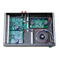
With Antek Transformer
Brand:
AkitikA
| Category:
Amplifier
| Size: 1 MB
Advertisement
Related Products
AkitikA GT-101 STEREO
AkitikA GT100
AkitikA GT-102
AkitikA GT-108
AkitikA DYNACO STEREO 120
AkitikA EE-101
AkitikA EE-101NP
AkitikA EE101MECH
AkitikA PAT-4
AkitikA PAT4PPR
AkitikA Categories
Amplifier
Switch
Computer Hardware
More AkitikA Manuals
Login
Sign In
OR
Sign in with Facebook
Sign in with Google
Upload manual
Upload from disk
Upload from URL