
Subscribe to Our Youtube Channel
Related Manuals for PASCO ME-9502


Summary of Contents for PASCO ME-9502
- Page 1 I n s t r u c t i o n M a n u a l ® 012-12876B *012-12876* PASCO Mechanics Statics System ME-9502...
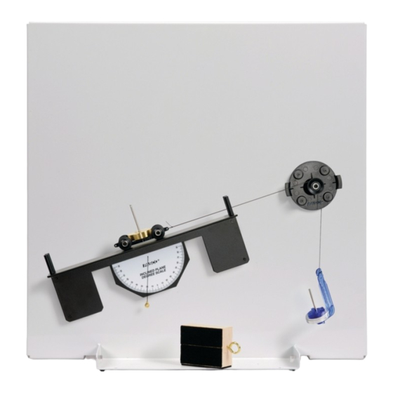
- Page 2 The cover page shows a a Friction Block on the Statics System Inclined Plane with a PASCO Mass Hanger from the ME-8979 Mass and Hanger Set suspended by a thread over a Small Pulley. Most of the components of the Statics System are held magnetically to the included workboard.
-
Page 3: Table Of Contents
Table of Contents Introduction ............1 Equipment . - Page 4 S t a t ic s S y s t e m ® 012-12876B...
-
Page 5: Introduction
Much of what is studied in an introductory course deals with the ways that forces interact with physical bodies. The PASCO Statics System is designed to help you investigate the nature of forces for the special case in which there is no acceleration. In other words, the vector sum of all the forces acting on the body is zero. - Page 6 S t a t ic s S y s t e m E q u i p m e n t Important When moving or removing any of the magnetically mounted compo- nents from the board, handle the component by the magnetic base rather than by the component itself.
-
Page 7: Recommended Equipment
Load Cell Amplifier (ScienceWorkshop) CI-6464 PS-2201 5 N Load Cell *See the PASCO catalog or Web site at www.pasco.com for information about PASCO load cells, load cell amplifiers, interfaces, hand-held data loggers, and data acquisition software. ® 0 1 2 - 1 2 8 7 6 B... -
Page 8: Spares Package
S p a r e s P a c k a g e ( M E - 9 5 0 4 ) Stopwatch (ME-1234) The PASCO Stopwatch has a liquid crystal dis- play (LCD) with two display modes. Its precision is 0.01 seconds up to 3599.99 seconds, and 1 sec-... -
Page 9: Components Package
M o d e l N o . M E - 9 5 0 2 C o m p o n e n t s P a c k a g e ( M E - 9 5 0 5 ) Components Package (ME-9505) Mounted Scale Assembly Top hook... - Page 10 S t a t i c s S y s t e m C o m p o n e n t s P a c k a g e ( M E - 9 5 0 5 ) Inclined Plane Assembly The Inclined Plane Assembly has four strong magnets on its back side that hold it in position on the Statics Board.
- Page 11 M o d e l N o . M E - 9 5 0 2 C o m p o n e n t s P a c k a g e ( M E - 9 5 0 5 ) Torque Wheel Assembly and Torque Indicator Assembly The Torque Wheel Assembly has a 5 cm radius disk with a Base...
- Page 12 S t a t i c s S y s t e m C o m p o n e n t s P a c k a g e ( M E - 9 5 0 5 ) (Imagine that the Force Wheel disk is transparent so that you can see the String Tie.) Hold the Force Wheel as shown and push the clear plastic tabs inward with your forefingers until the String Tie pops out of the Force Wheel.
- Page 13 M o d e l N o . M E - 9 5 0 2 C o m p o n e n t s P a c k a g e ( M E - 9 5 0 5 ) Utility Mount Assembly Base The Utility Mount has several functions.
-
Page 14: About The Manual
Utility About the Manual Mount The ME-9502 Statics System provides an introduction to static mechanics. The experiments first introduce force as a vector quantity and then build on this concept so that students will understand the equi- librium of a physical body under the application of a variety of forces and torques. -
Page 15: Hooke's Law - Measuring Forces
M o d e l N o . M E - 9 5 0 2 E x p . 1 : H o o k e ’ s L a w — M e a s u r i n g F o r ce Exp. - Page 16 S t a t i c s S y s t e m E x p . 1 : H o o k e ’ s L a w — M e a s u r i n g F o r c e Data Table Spring Displacement (m) Mass (kg)
-
Page 17: Adding Forces - Resultants And Equilibriants
M o d e l N o . M E - 9 5 0 2 E x p . 2 : A d d i n g F o r c e s — R e s u l t a n t s a n d E q u i l i b r i a n t s Exp. - Page 18 S t a t i c s S y s t e m E x p . 2 : A d d i n g F o r c e s — R e s u l t a n t s a n d E q u i l i b r i a n t s Procedure: Two Forces Add or remove 0.5 g to the mass hanger.
- Page 19 M o d e l N o . M E - 9 5 0 2 E x p . 2 : A d d i n g F o r c e s — R e s u l t a n t s a n d E q u i l i b r i a n t s Analysis On a separate piece of graph paper, use the values you recorded in the table to construct a vector diagram for , and F...
- Page 20 S t a t i c s S y s t e m E x p . 2 : A d d i n g F o r c e s — R e s u l t a n t s a n d E q u i l i b r i a n t s ®...
-
Page 21: Resolving Forces - Components
M o d e l N o . M E - 9 5 0 2 E x p . 3 : R e s o l v i n g F o r c e s — C o m p o n e n t s Exp. - Page 22 S t a t i c s S y s t e m E x p . 3 : R e s o l v i n g F o r c e s — C o m p o n e n t s What are the magnitudes of F and F , the x- and y-components of F?
- Page 23 M o d e l N o . M E - 9 5 0 2 E x p . 3 : R e s o l v i n g F o r c e s — C o m p o n e n t s Question Is the force disk at equilibrium in the center of the Force Wheel? Why or why not?
- Page 24 S t a t i c s S y s t e m E x p . 3 : R e s o l v i n g F o r c e s — C o m p o n e n t s ®...
-
Page 25: Torque - Parallel Forces
M o d e l N o . M E - 9 5 0 2 E x p . 4 : T o r q u e — P a r a l l e l F o r c e s Exp. - Page 26 S t a t i c s S y s t e m E x p . 4 : T o r q u e — P a r a l l e l F o r c e s Procedure: Equal Distance, Equal Mass Position one of the protractors near one end the beam and tighten its thumbscrew to hold it in place.
- Page 27 M o d e l N o . M E - 9 5 0 2 E x p . 4 : T o r q u e — P a r a l l e l F o r c e s Data Table Case Total Mass...
- Page 28 S t a t i c s S y s t e m E x p . 4 : T o r q u e — P a r a l l e l F o r c e s ®...
-
Page 29: Center Of Mass
M o d e l N o . M E - 9 5 0 2 E x p . 5 A : C e n t e r o f M a s s Exp. 5A: Center of Mass Equipment Needed Item Item Statics Board... - Page 30 S t a t i c s S y s t e m E x p . 5 A: C e n t e r o f M a s s Level the Beam and Mark the Center of Mass Loosen the thumbscrew and adjust the beam so that the indicator marks on the pivot are aligned with the zero mark on the beam.
- Page 31 M o d e l N o . M E - 9 5 0 2 E x p . 5 A : C e n t e r o f M a s s • Recalculate the torques about the pivot point. Position Force (F = mg) Torque (...
- Page 32 S t a t i c s S y s t e m E x p . 5 A: C e n t e r o f M a s s ® 012-12876B...
-
Page 33: Equilibrium Of Physical Bodies
M o d e l N o . M E - 9 5 0 2 E x p . 5 B: E q u i l i b r i u m o f P h y s i c a l B o d i e s Exp. - Page 34 S t a t i c s S y s t e m E x p . 5 B : E q u i l i b r i u m o f P h y s i c a l B o d i e s Data Table.
- Page 35 M o d e l N o . M E - 9 5 0 2 E x p . 5 B: E q u i l i b r i u m o f P h y s i c a l B o d i e s Data Table: Change the Origin.
- Page 36 S t a t i c s S y s t e m E x p . 5 B : E q u i l i b r i u m o f P h y s i c a l B o d i e s ®...
-
Page 37: Torque - Non-Parallel Forces
M o d e l N o . M E - 9 5 0 2 E x p . 6 : T o r q u e — N o n - P a r a l l e l F o r c e s Exp. - Page 38 S t a t i c s S y s t e m E x p . 6 : T o r q u e — N o n - P a r a l l e l F o r c e s Suspend a mass, M , from one protractor.
- Page 39 M o d e l N o . M E - 9 5 0 2 E x p . 6 : T o r q u e — N o n - P a r a l l e l F o r c e s Perform the calculations to determine the torque, ...
- Page 40 S t a t i c s S y s t e m E x p . 6 : T o r q u e — N o n - P a r a l l e l F o r c e s Set Up the Torque Wheel Torque Torque...
-
Page 41: The Inclined Plane
M o d e l N o . M E - 9 5 0 2 E x p . 7 : T h e I n c l i n e d P l a n e Exp. 7: The Inclined Plane Equipment Needed Item Item... - Page 42 S t a t i c s S y s t e m E x p . 7 : T h e I n c l i n e d P l a n e The force provided by the Spring Scale, F , equals the component of the force of gravity that is parallel to ...
- Page 43 M o d e l N o . M E - 9 5 0 2 E x p . 7 : T h e I n c l i n e d P l a n e Record the total mass of the mass hanger and calculate and record the weight. •...
- Page 44 S t a t i c s S y s t e m E x p . 7 : T h e I n c l i n e d P l a n e ® 012-12876B...
-
Page 45: Sliding Friction And Static Friction
M o d e l N o . M E - 9 5 0 2 E x p . 8 : S l i d i n g F r i c t i o n Exp. 8: Sliding Friction Equipment Needed Item Item... - Page 46 S t a t i c s S y s t e m E x p . 8 : S l i d i n g F r i c t i o n • If the Friction Block stops, the mass is too light. If the Friction Block accelerates, the mass is too heavy. •...
- Page 47 M o d e l N o . M E - 9 5 0 2 S l i d i n g F r i c t i o n o n a n I n c l i n e d P l a n e Questions In trials 1 through 6, what happens to the sliding friction as the normal force increases? In trials 1 through 6, what happens to the coefficient of friction as the normal force increases?
- Page 48 S t a t i c s S y s t e m S l i d i n g F r i c t i o n o n a n I n c l i n e d P l a n e Procedure The thread must be parallel...
- Page 49 M o d e l N o . M E - 9 5 0 2 S t a t i c F r i c t i o n o n a n I n c l i n e d P l a n e Static Friction on an Inclined Plane Imagine that the Friction Block is placed on the Inclined Plane, and one end of the plane is tilted upward until the parallel component of the block’s weight begins to pull the block down the plane.
- Page 50 S t a t i c s S y s t e m S t a t i c F r i c t i o n o n a n I n c l i n e d P l a n e ®...
-
Page 51: Simple Harmonic Motion - Mass On A Spring
M o d e l N o . M E - 9 5 0 2 E x p . 9 : S i m p l e H a r m o n i c M o t i o n – M a s s o n a S p r i n g Exp. - Page 52 S t a t i c s S y s t e m E x p . 9 : S i m p l e H a r m o n ic M o t i o n – M a s s o n a S p r i n g Pull the mass hanger down and release it smoothly.
- Page 53 M o d e l N o . M E - 9 5 0 2 E x p . 9 : S i m p l e H a r m o n i c M o t i o n – M a s s o n a S p r i n g Extension In addition to the hanging mass, there is other mass that is oscillating up and down.
- Page 54 S t a t i c s S y s t e m S i m p l e H a r m o n i c M o t i o n – B e a m o n a S p r in g Simple Harmonic Motion–Beam on a Spring Imagine a horizontal beam that is supported by a hinge at one end and a vertical spring at the other end.
- Page 55 M o d e l N o . M E - 9 5 0 2 S i m p l e H a r m o n i c M o t i o n – B e a m o n a S p r in g In this part of the experiment you will investigate this equation for the simple harmonic motion of a beam on a spring.
- Page 56 S t a t i c s S y s t e m S i m p l e H a r m o n i c M o t i o n – B e a m o n a S p r in g Data Table Trial Oscillations...
-
Page 57: Simple Harmonic Motion - The Simple Pendulum
M o d e l N o . M E - 9 5 0 2 E x p . 1 0 : S i m p l e H a r m o n i c M o t i o n – T h e S i m p l e P e n d u l u m Exp. - Page 58 S t a t i c s S y s t e m E x p . 1 0 : S i m p l e H a r m o n i c M o t i o n – T h e S i m p l e P e n d u l u m Procedure Place the Utility Mount near the top edge of the Statics Board.
- Page 59 M o d e l N o . M E - 9 5 0 2 E x p . 1 0 : S i m p l e H a r m o n i c M o t i o n – T h e S i m p l e P e n d u l u m Data Table Mass 1 (kg) Length 2 (m)
- Page 60 S t a t i c s S y s t e m E x p . 1 0 : S i m p l e H a r m o n i c M o t i o n – T h e S i m p l e P e n d u l u m ®...
-
Page 61: Simple Harmonic Motion - Physical Pendulum
M o d e l N o . M E - 9 5 0 2 E x p . 1 1 A : S i m p l e H a r m o n i c M o t i o n – P h ys i c a l P e n d u l u m Exp. - Page 62 S t a t i c s S y s t e m E x p . 1 1 A : S i m p l e H a r m o n ic M o t i o n – P h y s i c a l P e n d u l u m In this part of the experiment you will investigate this equation for the period of the simple harmonic motion of a physical pendulum with a fixed distance between the pivot point and the center of mass.
- Page 63 M o d e l N o . M E - 9 5 0 2 E x p . 1 1 A : S i m p l e H a r m o n i c M o t i o n – P h ys i c a l P e n d u l u m Does the equation for the theoretical period of this physical pendulum provide a good mathematical model for the physical reality? Why or why not? Try This...
- Page 64 S t a t i c s S y s t e m E x p . 1 1 A : S i m p l e H a r m o n ic M o t i o n – P h y s i c a l P e n d u l u m Extension: Period of Oscillation for Large Angles The motion of a physical pendulum is simple harmonic motion for small angles.
- Page 65 M o d e l N o . M E - 9 5 0 2 E x p . 1 1 A : S i m p l e H a r m o n i c M o t i o n – P h ys i c a l P e n d u l u m Stretch one of the threads from the Force Disk to the arc on the board.
- Page 66 S t a t i c s S y s t e m E x p . 1 1 A : S i m p l e H a r m o n ic M o t i o n – P h y s i c a l P e n d u l u m ®...
-
Page 67: Minimum Period For A Physical Pendulum
M o d e l N o . M E - 9 5 0 2 E x p . 1 1 B : M i n i m u m P e r i o d o f a P h y s i c a l P e n d u l u m Exp. - Page 68 S t a t i c s S y s t e m E x p . 1 1 B : M i n i m u m P e r i o d o f a P h y s i c a l P e n d u l u m Procedure Move the pivot of the Balance Arm to a position one centimeter (cm) above the midpoint of the beam (presumably the center of mass of the beam).
- Page 69 M o d e l N o . M E - 9 5 0 2 E x p . 1 1 B : M i n i m u m P e r i o d o f a P h y s i c a l P e n d u l u m Calculations For each distance, L , calculate and record the Measured Period by dividing the total time by the number of...
- Page 70 S t a t i c s S y s t e m E x p . 1 1 B : M i n i m u m P e r i o d o f a P h y s i c a l P e n d u l u m ®...
-
Page 71: Simple Harmonic Motion - Beam On A Spring
M o d e l N o . M E - 9 5 0 2 E x p . 1 1 C : S i m p l e H a r m o n i c M o t i o n – B e a m o n a S p r i n g Exp. - Page 72 S t a t i c s S y s t e m E x p . 1 1 C : S i m p l e H a r m o n i c M o t i o n – B e a m o n a S p r i n g where I is the moment of inertia and k is the spring constant.
- Page 73 M o d e l N o . M E - 9 5 0 2 E x p . 1 1 C : S i m p l e H a r m o n i c M o t i o n – B e a m o n a S p r i n g 10.
- Page 74 S t a t i c s S y s t e m E x p . 1 1 C : S i m p l e H a r m o n i c M o t i o n – B e a m o n a S p r i n g Data Table Oscillations Total Time (s)
- Page 75 M o d e l N o . M E - 9 5 0 2 E x p . 1 1 C : S i m p l e H a r m o n i c M o t i o n – B e a m o n a S p r i n g Extension •...
- Page 76 S t a t i c s S y s t e m E x p . 1 1 C : S i m p l e H a r m o n i c M o t i o n – B e a m o n a S p r i n g ®...
-
Page 77: Simple Machines - The Lever
M o d e l N o . M E - 9 5 0 2 E x p . 1 2 : S i m p l e M a c h i n e s – T h e L e v e r Exp. - Page 78 S t a t i c s S y s t e m E x p . 1 2 : S i m p l e M a c h i n e s – T h e L e v e r Mount a Large Pulley and Spring Scale at one end of the Balance Arm and use thread to connect the Spring Scale to the Protractor on the Balance Arm.
- Page 79 M o d e l N o . M E - 9 5 0 2 E x p . 1 2 : S i m p l e M a c h i n e s – T h e L e v e r Data Table Item Trial 1...
- Page 80 S t a t i c s S y s t e m E x p . 1 2 : S i m p l e M a c h i n e s – T h e L e v e r A wheelbarrow is an example of a Class II Lever, and the human forearm is an example of a Class III Lever.
-
Page 81: Simple Machines - The Inclined Plane
M o d e l N o . M E - 9 5 0 2 E x p . 1 3 : S i m p l e M a c h i n e s – T h e I n c l i n e d P l a n e Exp. - Page 82 S t a t i c s S y s t e m E x p . 1 3 : S i m p l e M a c h i n e s – T h e I n c l i n e d P l a n e Measure and record the magnitude of the force, F , exerted by the Spring Scale on the Mass Cart, and the ...
- Page 83 M o d e l N o . M E - 9 5 0 2 E x p . 1 3 : S i m p l e M a c h i n e s – T h e I n c l i n e d P l a n e sin the height to Slowly push the Spring Scale straight up a distance, d which the Mass Cart was raised when it was on the Inclined Plane.
- Page 84 S t a t i c s S y s t e m E x p . 1 3 : S i m p l e M a c h i n e s – T h e I n c l i n e d P l a n e ®...
-
Page 85: Simple Machines - The Pulley
M o d e l N o . M E - 9 5 0 2 E x p . 1 4 : S i m p l e M a c h i n e s – T h e P u l l e y Exp. - Page 86 S t a t i c s S y s t e m E x p . 1 4 : S i m p l e M a c h i n e s – Th e P u l l e y Use a pencil or dry erase marker pen to outline the base of the Spring Scale.
-
Page 87: Forces On A Boom
M o d e l N o . M E - 9 5 0 2 E x p . 1 5 : F o r c e s o n a B o o m Exp. 15: Forces on a Boom Equipment Needed Item Item... - Page 88 S t a t i c s S y s t e m E x p . 1 5 : F o r c e s o n a B o o m Procedure Set up the Balance Arm with the Protractor pivot at one end, a protractor at the Spring...
-
Page 89: Technical Support, Warranty, And Copyright
M o d e l N o . M E - 9 5 0 2 E x p . 1 6 : M o d i f i e d A t w o o d ’ s M a c h i n e Exp. - Page 90 S t a t i c s S y s t e m E x p . 1 6 : M o d i f i e d A t w o o d ’ s M a c h i n e Setup Place the two Small Pulleys on the Statics Board near the top edge of the board and close to each other.
- Page 91 M o d e l N o . M E - 9 5 0 2 E x p . 1 6 : M o d i f i e d A t w o o d ’ s M a c h i n e Data Table 1: Constant Total Mass M (kg) Trial...
- Page 92 S t a t i c s S y s t e m E x p . 1 6 : M o d i f i e d A t w o o d ’ s M a c h i n e Calculate and record the percent difference of the theoretical acceleration and the measured acceleration for each trial.
- Page 93 Email: support@pasco.com For more information about the Statics System and the latest revision of this Instruction Manual, visit the PASCO web site and enter ME-9502 into the Search window. Limited Warranty For a description of the product warranty, see the PASCO catalog.
- Page 94 S t a t ic s S y s t e m T e c h n ic a l S u p p o r t ® 012-12876B...
Need help?
Do you have a question about the ME-9502 and is the answer not in the manual?
Questions and answers