Table of Contents
Advertisement
Available languages
Available languages
Quick Links
Università Cattolica del Sacro Cuore
Facoltà di Scienze matematiche, fisiche e naturali
a.a. 2012/2013
Laboratorio di Fisica
a
(2
unità)
- Schede di presentazione delle esperienze -
Docenti:
Galimberti Gianluca
Maianti Marco
Indice:
Esperienza 1: Momento di inerzia.
Esperienza 2: Conservazione del momento angolare.
Esperienza 3: Moti oscillatori accoppiati.
Esperienza 4: Pendolo di torsione.
Esperienza 5: Trasformazioni termodinamiche.
Esperienza 6: Motore termico.
Esperienza 7: Sonometro
Calendario e suddivisione dei gruppi
Advertisement
Chapters
Table of Contents

Related Manuals for PASCO TD-8565


Summary of Contents for PASCO TD-8565
- Page 1 Università Cattolica del Sacro Cuore Facoltà di Scienze matematiche, fisiche e naturali a.a. 2012/2013 Laboratorio di Fisica unità) - Schede di presentazione delle esperienze - Docenti: Galimberti Gianluca Maianti Marco Indice: Esperienza 1: Momento di inerzia. Esperienza 2: Conservazione del momento angolare. Esperienza 3: Moti oscillatori accoppiati.
- Page 2 Esperienza 2 –Conservazione del momento angolare Momento di inerzia di una massa puntiforme Scopo Lo scopo di questo esperimento è la determinazione sperimentale del momento di inerzia di una massa puntiforme e la verifica che questo valore corrisponde a quello che si calcola teoricamente.
- Page 3 Esperienza 2 –Conservazione del momento angolare Sostituendo le Eqq. (5) e (6) in Eq. (2) si trova: § · ¨ ¨ ¸ ¸ © ¹ Quindi il momento di inerzia I può essere calcolato dall’accelerazione tangenziale a Procedura 1) Attaccare una massa su entrambi i lati dell'asta in posizioni equidistanti dal centro. La distanza dal centro a cui porre le masse è...
- Page 4 Esperienza 2 –Conservazione del momento angolare Raccolta dei dati Ricordate: per dare inizio alla raccolta, potete, a vostra scelta: fare click sul tasto “REC”, selezionare “Record” dal menù Experiment, premere “ALT R”. Per terminare la raccolta: fare click sul tasto “STOP”, selezionare “Stop”...
- Page 5 Esperienza 2 –Conservazione del momento angolare Momento di inerzia di un disco e di un anello Scopo Lo scopo di questo esperimento è la determinazione sperimentale del momento di inerzia di un anello ed un disco e la verifica che questo valore corrisponda a quello che si calcola. Teoria Il momento di inerzia di un anello è...
- Page 6 Esperienza 2 –Conservazione del momento angolare Parte I : Calcolo teorico del momento di inerzia 1) Pesare il disco e l'anello per trovare le loro masse 2) Misurare i diametri interno ed esterno dell'anello e calcolare i raggi 3) Misurare il diametro del disco e calcolare il raggio Parte II Misura del momento di inerzia - Trovare l'accelerazione delle masse puntiformi e dell'apparato 1) Far partire Science Workshop...
- Page 7 Esperienza 2 –Conservazione del momento angolare Poiché nella rotazione sia il disco che l'anello ruotano insieme è necessario determinare l'accelerazione ed il momento di inerzia del disco da solo cosicché il suo momento di inerzia possa essere sottratto dal totale per trovare il momento di inerzia dell'anello. - Rimuovere il disco dall'apparato e ripetere la procedura da 1) ad 8).
- Page 8 Esperienza 2 –Conservazione del momento angolare Conservazione Momento Angolare Scopo Un anello è fatto cadere su un disco rotante e la velocita' angolare finale del sistema è confrontata con il valore predetto usando la conservazione del momento angolare. Apparati richiesti : Interfaccia per Science Workshop Accessori per il mini-sistema rotazionale Base ed asta di supporto...
- Page 9 Esperienza 2 –Conservazione del momento angolare Calcoli Calcolare il valore aspettato per la velocità angolare finale. Calcolare la differenza percentuale tra il valore sperimentale e quello teorico della velocità angolare.
- Page 10 Esperienza 3 – Moti oscillatori accoppiati Oscillatori Accoppiati - Modi Normali di Oscillazione Materiale richiesto Rotaia con 2 carrelli, massa addizionale e stop 3 molle (Set di masse e sistema di sospensione Filo Carrucola Cronometro) Bilancia Sensore di moto Interfaccia per Science Workshop/DataStudio Scopo Lo scopo dell'esperienza è...
- Page 11 Esperienza 3 – Moti oscillatori accoppiati Procedura (Oscillatori Accoppiati) Misura delle frequenze angolari normali di oscillazione del sistema 1. Per suscitare il solo modo normale “somma” di oscillazione, spostare i due carrelli dalla posizione di equilibrio di uno stesso tratto e dalla stessa parte e lasciarli quindi liberi nello stesso istante ;...
- Page 12 Esperienza 3 – Moti oscillatori accoppiati x Selezionare “Motion Sensor” nel menù dei sensori digitali. 3. Nella finestra delle caratteristiche del sensore è possibile calibrare il sensore e stabilire il numero di dati da registrare al secondo : x per calibrare : puntare il sensore su un oggetto fermo alla distanza di 1 metro (la distanza di calibrazione predisposta) e selezionare “calibrate”, il programma calcolerà...
- Page 13 Esperienza 4 – Pendolo di torsione ENDOLO DI ORSIONE SCOPO Misurare il valore del momento di inerzia (I) di un disco e di un cilindro, usando la costante di torsione del filo (k) e o periodo di oscillazione del pendolo di torsione (T), confrontando con il valore teorico.
- Page 14 Esperienza 4 – Pendolo di torsione TEORIA Quando viene applicato un momento esterno tale da operare una torsione sul filo rigido, questo reagisce con un momento torcente che dipende linearmente dalla variazione angolare: torcente dove k è una costante - detta di torsione - che dipende dal materiale e dalle dimensioni del filo. La relazione (1) è...
- Page 15 Esperienza 4 – Pendolo di torsione 4. Aggiungere delle masse sul portapesi appeso alla puleggia e attendere che il sistema si stabilizzi per prendere la misura dell’angolo di torsione. 5. Fare il grafico della posizione angolare del SMR in funzione della forza peso applicata e fittare i dati con la retta dei minimi quadrati.
- Page 16 Includes Instruction Manual and 012-05110C Teacher's Notes 5/94 Typical Experiment Guide for Experiment Results the PASCO scientific Model TD-8565 Adiabatic Gas Law Apparatus © 1993 PASCO scientific $7.50...
-
Page 18: Table Of Contents
How to Use this Manual ................1 Theory ........................2 Description of Apparatus ..................3 Setup: Using the TD-8565 with the PASCO Series 6500 Computer Interface ..5 IBM compatible computers ................5 Apple II compatible computers ..............7 Expansion of a Gas ..................7 Experiment: Measurement of Work to Compress Gases Adiabatically ...... -
Page 19: Copyright, Warranty And Equipment Return
Copyright Notice Equipment Return The PASCO scientific Model TD-8565 Adiabatic Gas Should the product have to be returned to PASCO Law Apparatus manual is copyrighted and all rights scientific for any reason, notify PASCO scientific by reserved. However, permission is granted to non- letter, phone, or fax BEFORE returning the product. -
Page 20: Introduction
Other: Equipment Included: • The Adiabatic Gas Law Apparatus can also be The TD-8565 consists of the Adiabatic Gas Law used with the MultiPurpose Lab Interface Apparatus and this instruction manual (part number (MPLI) from Vernier Software. -
Page 21: Theory
Adiabatic Gas Law Apparatus 012-05110C Theory When a process takes place without thermal energy γ – 1 γ – 1 entering or leaving the system it is an adiabatic Another relationship to be examined in this experi- process. This would occur if the system were per- ment is the energy expended or work done on the fectly thermally insulated or if the process occurred so gas while compressing it adiabatically. -
Page 22: Description Of Apparatus
012-05110C Adiabatic Gas Law Apparatus Description of Apparatus A piston, Fig 2, item a, made of acetal plastic is As mentioned above, the electronic circuit consists of manually driven down or up in an acrylic cylinder, Fig the two amplifiers with bridge excitation sources. The 2, item b, which is filled with any of several gases, electronics may be powered with an external "floating including monatomic argon, diatomic air or nitrogen,... - Page 23 Adiabatic Gas Law Apparatus 012-05110C Ž Volume: For some of the calculations only the ini- Interpretation of Transducer Outputs: tial and final volumes are needed. These can be The apparatus comes with a small card that gives determined by reading the transparent scale located information about how to interpret the output voltage on the front of the cylinder.
-
Page 24: Setup
012-05110C Adiabatic Gas Law Apparatus Setup Connecting the Voltage Supply Using the TD-8565 with the PASCO Series 6500 Computer Interface Install a nine volt battery (not included) in the battery IBM compatible computers compartment located on the front of the electronics Œ... - Page 25 Adiabatic Gas Law Apparatus 012-05110C ’ C: Pressure: Hold the piston at a high position, and Return to the 'scope and press "S"for single-sweep press <Enter> when the reading has stabilized. mode. Move the piston down sharply to see if all The pressure in Pascals is 100,000 times the three traces are showing correctly.
-
Page 26: Apple Ii Compatible Computers
012-05110C Adiabatic Gas Law Apparatus z Once the data is obtained, return to the main menu Apple II compatible computers and choose “P” to plot the data. The best graphs are ® NOTE: Operation with the Apple II series of obtained when the inputs are uncalibrated;... - Page 27 Adiabatic Gas Law Apparatus 012-05110C Notes:...
-
Page 28: Measurement Of Work To Compress Gases Adiabatically
012-05110C Adiabatic Gas Law Apparatus Experiment: Measurement of Work to Compress Gases Adiabatically EQUIPMENT NEEDED: Optional: – Adiabatic Gas Law Apparatus, -Monatomic, Diatomic, – Series 6500 Computer Interface. and Polyatomic Gases. Purpose γ γ (γ–1) (γ–1) The purpose of this experiment is to show , To determine the value of Gamma, and to measure the amount of work done to compress a gas adiabatically. -
Page 29: Graphs And Data Tables
Adiabatic Gas Law Apparatus 012-05110C Graphs and Data Tables Now compress the gas while taking data as described in the Setup portion of your manual. Obtain graphs and a data table for analysis. Calculations ΠFrom your graphs or data table determine the final pressure and temperature at the time the compression was completed. -
Page 30: Schematic
012-05110C Adiabatic Gas Law Apparatus Schematic... -
Page 31: Specifications / Sample Data
Specifications / Sample Data Specifications Sample Data Operating Voltage: Data taken with an IBM PC and a PASCO Series 6500 9-15 volts DC or 9 volt battery. Higher voltage will Interface. provide capability of increased range in temperature and pressure measurements. A floating power supply is required. -
Page 32: Technical Support
• If your problem is with the PASCO apparatus, note: manual please tell us. PASCO appreciates any cus- tomer feed-back. Your input helps us evaluate and Title and Model number (usually listed on the label). - Page 34 TD-8572 Apparato per le leggi sui gas Motore termico Manuale di istruzioni Con esperimenti Ultima revisione: 10/08/2003 ELIt alia Srl – Via A. G ross ich 3 2 20131 Mi lan o – tel 02 .236.397 2 elit ali a@micron et.it – www.elit ali a.it...
- Page 35 Le spese di spedizione, per la restituzione dopo la riparazione, sono a carico della PASCO Note per la restituzione Prima di restituire, per qualsiasi motivo, il prodotto alla PASCO , è necessario avvertire la PASCO lettera o per telefono. Solo dopo questa comunicazione verranno fornite l'autorizzazione alla restituzione e le istruzioni per la spedizione.
- Page 36 Indice Supporto tecnico Introduzione Esperimento 1: l' ascensore termico Esperimento 2: legge di Charles Esperimento 3: legge di Boyle Esperimento 4: legge dei gas combinata (Gay Lussac) Esperimento 5: la macchina termica per sollevare masse...
-
Page 37: Supporto Tecnico
Supporto Tecnico Feed-back Tipo e modello dell' apparato PASCO che • state utilizzando (normalmente tutte le Se avete un qualsiasi commento su questo informazioni sono su un' etichetta sul prodotto, o sul manuale, fatecelo sapere. prodotto stesso, o sulla confezione). -
Page 38: Introduzione
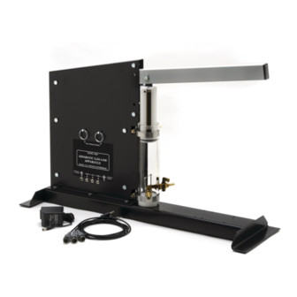
Introduzione Il Motore Termico/Apparato per la legge dei gas PASCO TD-8572 può essere utilizzato per esperimenti sia qualitativi che quantitativi, riguardo la legge dei gas perfetti, e per indagini su un motore termico funzionante. L' utilizzo di strumentazione on-line (sensori di pressione e di posizione) permette di misurare la quantità... - Page 39 L’apparato comprende: Motore termico vero e proprio (vedi figura) • Diametro del pistone 32.5 mm ± 0.1 • Massa di pistone e piattaforma portamassa (tutta la parte mobile) 35.0 g ± 0.6 • Camerina d' espansione (vedi figura) • 3 configurazioni di tubi •...
-
Page 40: Esperimento 1: L'ascensore Termico
Esperimento 1: l’ascensore termico Apparati richiesti Motore termico/Apparato per la legge dei gas Contenitore con acqua ghiacciata Masse 100 – 200 g Contenitore con acqua calda Teoria: Questo esperimento è puramente qualitativo. Si dimostra che una differenza di temperatura è sufficiente per compiere un lavoro. - Page 41 Note: Maggiore è la differenza di temperatura tra i bagni e maggiore sarà l’innalzamento del pistone e • quindi il lavoro prodotto ad ogni ciclo. Verificatelo. Di quanto si alza ogni volta la massa? Potete misurarlo con la scala millimetrata del motore termico. •...
-
Page 42: Esperimento 2: Legge Di Charles
Esperimento 2: legge di Charles Apparati richiesti Motore termico/Apparato per la legge dei gas Becker con acqua bollente Termometro Ghiaccio Equipaggiamento opzionale Sensore di temperatura Sensore di distanza ad ultrasuoni (o posizione angolare) Interfaccia per computer Science workshop Teoria: La legge di Charles afferma che, a pressione costante, il volume di una certa quantità di gas varia in modo direttamente proporzionale alla sua temperatura assoluta: V = cT (dove c è... - Page 43 Procedimento: 1. Immergere la camera d’aria nel contenitore di acqua bollente: l’aria, espandendosi, spinge il pistone; quando il sistema si stabilizza registrare la temperatura e la posizione del pistone; se invece si dispone di Science Workshop, iniziare l’acquisizione dei dati. 2.
-
Page 44: Esperimento 3: Legge Di Boyle
Esperimento 3: legge di Boyle Apparati richiesti Motore termico/Apparato per la legge dei gas Interfaccia per computer Science workshop, modello "300" o superiore. Sensore di pressione (CI-6532) Per dettagli sull’impostazione del sensore di pressione con Science workshop, consultare il foglio di istruzioni del sensore e il manuale utente di Science workshop. - Page 45 Note: Per minimizzare l' errore sul volume dovuto all' aria presente nel tubo, utilizzate un collegamento il • più corto possibile tra il sensore e l' attacco sul motore termico. Tagliate, a questo scopo, un pezzo di tubo di un centimetro e mezzo circa. Per pressioni vicine al limite di tenuta del motore termico la relazione tra P e V può...
-
Page 46: Esperimento 4: Legge Dei Gas Combinata (Gay Lussac)
Esperimento 4: legge dei gas combinata (Gay-Lussac) Apparati richiesti Motore termico/Apparato per la legge dei gas Fornelletto elettrico Sensore di pressione (CI-6532) Beker in pyrex con acqua Interfaccia per computer Science workshop, modello "300" o Ghiaccio superiore Sensore di temperatura (CI-6505) Per dettagli sull’impostazione dei sensori di pressione e temperatura con Science Workshop, consultare il foglio di istruzioni dei sensori e il manuale utente di Science Workshop. - Page 47 4. Inserire il sensore di temperatura nell’altro foro del tappo (Per facilitare l’ingresso ed evitare danni alla sonda è possibile utilizzare un lubrificante al silicone). Nota: è possibile sostituire il sensore di temperatura con un comune termometro facendo attenzione che il bulbo del termometro stesso non tocchi il fondo del recipiente.
-
Page 48: Esperimento 5: La Macchina Termica Per Sollevare Masse
Esperimento 5: la macchina termica per sollevare masse Apparati richiesti Motore termico/Apparato per la legge dei gas 2 beaker in pyrex con acqua 1 set di masse tra 20 g e 200 g 1 fornelletto Ghiaccio Equipaggiamento opzionale Sensore di posizione Sensore di pressione (CI-6532) Interfaccia per computer Science workshop Teoria:... - Page 49 * Disponendo dei sensori di pressione e posizione, collegare il sensore di pressione al connettore libero e quello di posizione al piatto del pistone; impostare Science Workshop in modo da visualizzare i dati raccolti in un grafico con la posizione (direttamente proporzionale al volume) in ascissa e la pressione in ordinata.
- Page 50 Model WA-9611, and 9613 SONOMETER WA-9613 WA-9613 DRIVER DETECTOR KEEP WEIGHTS AS NEAR TO FLOOR CAUTION! WA-9611 AS POSSIBLE IN THE EVENT THE 1.75 kg MAXIMUM SONOMETER SONOMETER WIRE SHOULD BREAK LOAD ON LEVER 100.5 Hz © 1988 PASCO scientific $5.00...
- Page 52 Setup and Operation ..................2 Using the Sonometer and the WA-9613 Driver/Detector Coils: Sonometer w/WA-9613, Driver/Detector Coils ........... 3 Sonometer and Driver/Detector w/PASCO Computer Interface ....4 Power Amplifier w/Series 6500 Computer Interface ........4 Power Amplifier w/CI-6550 or CI-6565 Computer Interface ....... 4 Function Generator w/Series 6500 Computer Interface ........
-
Page 53: Copyright, Warranty And Equipment Return
Carriers will not accept year from the date of shipment to the customer. PASCO will repair or replace, at its option, any part of the product... -
Page 54: Introduction
Introduction Introduction n = number of antinodes V = velocity of wave propagation The PASCO scientific Model WA-9611 Sonometer is an T = string tension enhanced version of the classic sonometer. You can per- m = linear density of string... -
Page 55: Setup And Operation
Sonometer 012-03489E Setup and Operation To setup the sonometer (see Figure 2): Brass string retainer ➀ Choose one of the ten strings and place the brass string retainer into the slot on the tensioning lever. Crimped lug ➁ Loosen the string adjustment screw and place the crimped lug that is attached to the other end of the string over the screw head, as shown. -
Page 56: Using The Sonometer And The Wa-9613 Driver/Detector Coils
Connect the driver coil directly to the output of the quency, you should see the motion of the string and PASCO PI-9587B Digital Function Generator. Con- the sound produced by the vibrating string should be a nect the detector coil directly to channel two of an os- maximum. - Page 57 Computer Interface fier. Show channel A and channel C on the screen, so There are several ways to use a PASCO Computer Inter- you can see both the driving force and the resultant face with the sonometer. The method you use depends on motion of the wire.
- Page 58 E X T E R N Model CI-6508 Ω INPUT ADAPTOR R T Z I N P FOR USE WITH PASCO SERIES 6500 INTERFACES CI-6510 SIGNAL INTERFACE ANALOG CHANNELS GAIN SELECT FOR USE WITH PASCO SERIES 6500 SENSORS A M P L I T U ▲...
- Page 59 Sonometer 012-03489E CI-6503 Voltage Sensor to the BNC adapter. Connect ➂ Set the function generator to produce a sine wave. Set the DIN plug of the Voltage Sensor to channel A of the frequency to a value between 100 and 200 Hz. Ad- the interface.
-
Page 60: Replacing Sonometer Strings
012-03489E Sonometer ➤NOTES: ➂ You will occasionally see higher and lower fre- quencies superimposed on the primary waveform. It ➀ The frequency observed on the wire may not be is possible for multiple standing waves to form. For the frequency of the driver. Usually it is twice the example, the wire may vibrate at the driver frequency driver frequency, since the driver electromagnet and twice the driver frequency at the same time, thus... -
Page 61: Theory Of Waves On A Stretched String
Sonometer 012-03489E Theory of Waves on a Stretched String Standing Waves Resonance The analysis above assumes that the standing wave is A simple sine wave traveling along a taut string can be formed by the superposition of an original wave and one described by the equation y sin 2π... - Page 62 012-03489E Sonometer If the analogy with Newton’s Law is accepted, and it is Experiments assumed that the wave velocity depends only on tension The two experiments are: and linear density, dimensional analysis shows that the • Resonance Modes of a Stretched String form of the equation must be as it is.
- Page 63 Sonometer 012-03489E Notes:...
-
Page 64: Experiment 1: Resonance Modes Of A Stretched String
012-03489E Sonometer Experiment 1: Resonance Modes of a Stretched String EQUIPMENT NEEDED: – WA-9611 Sonometer – Mass and mass hanger – WA-9613 Driver/Detector Coils – Dual trace oscilloscope – Function generator capable of delivering 0.5 amp Procedure ➀ Set up the Sonometer as shown in Figure 1.1. Start with the bridges 60 cm apart. - Page 65 Sonometer 012-03489E ➤ NOTE: The driving frequency of the signal generator may not be the frequency at which the wire is vibrating. By using a dual trace Vibrating oscilloscope, you can determine if the two frequencies are the same, Waveform or if the vibrating frequency is a multiple of the driving frequency, as shown in Figure 1.2.
-
Page 66: Experiment 2: Velocity Of Wave Propagation
012-03489E Sonometer Experiment 2: Velocity of Wave Propagation EQUIPMENT NEEDED: – WA-9611 Sonometer – WA-9613 Driver/Detector Coils – Function generator capable of delivering 0.5 amp – Dual trace oscilloscope – Mass and mass hanger Procedure ➀ Set up the Sonometer as shown in Figure 2.1. Set the bridges 60 cm apart. - Page 67 Sonometer 012-03489E ➃ In Table 2.1, record the string tension (T) and the linear String tension density of the string (µ). The tension is determined as shown in Figure 2.2. Just multiply the weight of the hanging mass by one, two, three, four, or five, depending on which notch of the tensioning lever the mass is hanging from.
- Page 68 012-03489E Sonometer Analysis ➀ Use your measured string length, the fundamental frequency, and the equation V = λν to determine the velocity of the wave on the string for each value of tension and linear density that you used. ➁ Determine the functional relationship between the speed of the wave (V) and the wire tension (T). This can be accomplished using either of the following three methods.
-
Page 69: Suggested Research Topics
Sonometer 012-03489E Suggested Research Topics The following are a few suggestions for further experimentation with the Sonometer. ➀ Obtain two wires of the same linear density (mass per unit length), one that is wound and one that is not wound (a plain wire). Investigate the effects of the winding on the mathematical relation- ships of wave propagation. -
Page 70: Teacher's Guide
012-03489E Sonometer Teacher’s Guide Experiment 1: Resonance Modes of a Stretched String Note Optional To avoid cross-talk between the detector and driver, keep ➀ Frequency v. Tension the detector coil at least 10 cm from the driver coil during 1600 measurements. - Page 71 Sonometer 012-03489E Note Notes on Conclusions ➀ As shown in Experiment 1, l = 2L/n. To avoid cross-talk between the detector and driver, keep the detector coil at least 10 cm from the driver coil during ➂ From the Analysis section, V = sqrt(T/µ). Since measurements.
-
Page 72: Technical Support
• If your problem is with the PASCO apparatus, note: manual please tell us. PASCO appreciates any cus- tomer feed-back. Your input helps us evaluate and Title and Model number (usually listed on the label). - Page 75 LABORATORIO DI FISICA GENERALE (PRIMO MODULO) A. A. 2012/2013 - Calendario esperienze in laboratorio - Gruppo Componenti Esp. 1 (date:2, 3 mag.) Esp. 2 (date: 9, 10 mag.) Colosini (mat) Guerini Bandera Devescovi Sonometro Quantità di moto (fis) Fiorentino Polvara Angeli Cademartori Pendolo di torsione...
Need help?
Do you have a question about the TD-8565 and is the answer not in the manual?
Questions and answers