Table of Contents
Advertisement
Quick Links
Advertisement
Table of Contents

Related Manuals for Amada HF-2500A


Summary of Contents for Amada HF-2500A
- Page 1 HIGH FREQUENCY WELD CONTROL HF-2500A OPERATION MANUAL 990-371 REV J...
- Page 2 Copyright © 1998 - 2021 AMADA WELD TECH INC. The engineering designs, drawings and data contained herein are the proprietary work of AMADA WELD TECH and may not be reproduced, copied, exhibited or otherwise used without the written authorization of AMADA WELD TECH.
- Page 3 Should questions arise, or if you have suggestions for improvement of this manual, please contact us at the above location/numbers. AMADA WELD TECH is not responsible for any loss or injury due to improper use of this product. This manual covers the following models:...
-
Page 4: Table Of Contents
Emergency Stop Switch Operation ....................1-8 Chapter 2. Installation and Setup Section I: Installation ..........................2-1 Unpacking ............................. 2-1 Space Requirements ......................... 2-1 Utilities ............................. 2-2 Power ............................. 2-2 Compressed Air and Cooling Water ..................2-2 HF-2500A HIGH FREQUENCY WELD CONTROL 990-371... - Page 5 1. Footswitch Weld Abort ..................... 3-11 2. Switch Debounce Time ..................... 3-11 3. Firing Switch ........................3-12 1. Auto ..........................3-12 2. None ........................... 3-12 3. Remote ........................3-12 Setup 2 ........................... 3-13 1. Display Contrast ........................ 3-13 HF-2500A HIGH FREQUENCY WELD CONTROL 990-371...
- Page 6 ....................4-2 PEAK AVERAGE MONITORING Current, Voltage, Power, and Resistance Limits ................4-3 Process Tools ........................... 4-3 1. Active Part Conditioner (APC) ................... 4-3 2. Resistance Set ........................4-5 3. Pre-Weld Check ........................4-6 HF-2500A HIGH FREQUENCY WELD CONTROL 990-371...
- Page 7 Alarm Messages ..........................6-1 Section II. Troubleshooting ........................6-2 Troubleshooting ..........................6-2 Alarm Messages ..........................6-3 Section III. Maintenance ........................6-8 Electrode Maintenance ........................6-8 Parts Replacement ........................... 6-8 Section IV. Repair Service ........................6-8 HF-2500A HIGH FREQUENCY WELD CONTROL 990-371...
- Page 8 Appendix E. Communications ......................E-1 Appendix F. The Basics of Resistance Welding ................F-1 Appendix G. Quality Resistance Welding Solutions: Defining the Optimum Process ....G-1 Appendix H. Compatibility and Comparison .................. H-1 HF-2500A HIGH FREQUENCY WELD CONTROL viii 990-371...
- Page 9 Never perform any welding operation without wearing protective safety glasses. This instruction manual describes how to operate, maintain and service the HF-2500A Power Supply, and provides instructions relating to its safe use. A separate manual provides similar information for the weld head used in conjunction with the power supply.
- Page 10 1. Applicability. (a) These terms and conditions of sale (these “Terms”) are the only terms which govern the sale of the goods (“Goods”) by Amada Weld Tech Inc. (“Seller”) to the buyer identified in the Sales Quotation and/or Acknowledgment (as each defined below) to which these Terms are attached or incorporated by reference (“Buyer”).
- Page 11 Software or documentation, and Buyer shall retain on all copies of the Software and documentation all copyright and other proprietary notices or legends appearing therein or thereon. Seller may terminate this license upon written notice for any violation of any of the terms of this license HF-2500A HIGH FREQUENCY WELD CONTROL 990-371...
- Page 12 MANUFACTURE, SALE, USE, OR INABILITY TO USE ANY GOODS, SOFTWARE OR SERVICE, ORARISING OUT OF OR RELATING TO ANY BREACH OF THESE TERMS, WHETHER OR NOT THE POSSIBILITY OF SUCH DAMAGES HAS BEEN DISCLOSED IN ADVANCE BY BUYER OR COULD HAVE BEEN REASONABLY HF-2500A HIGH FREQUENCY WELD CONTROL 990-371...
- Page 13 Buyer; (b) known to Buyer at the time of disclosure without restriction as evidenced by its records; or (c) rightfully obtained by Buyer on a non- confidential basis from a third party. HF-2500A HIGH FREQUENCY WELD CONTROL 990-371...
- Page 14 27. Survival. Provisions of these Terms which by their nature should apply beyond their terms will remain in force after any termination or expiration of this Order including, but not limited to, the following provisions: Compliance with Laws, Confidentiality, Governing Law, Dispute Resolution, Survival, and the restrictions on Software in Sections 10(b), (c) and (d). HF-2500A HIGH FREQUENCY WELD CONTROL 990-371...
-
Page 15: Chapter 1. Description Section I: Features
MODEL NUMBER STOCK NUMBER HF-2500A/240 1-315-02 HF-2500A/400 1-315-02-01 HF-2500A/480 1-315-02-02 NOTE: For the rest of this manual, the AMADA WELD TECH HF-2500A High Frequency Weld Control will simply be referred to as the Power Supply. HF-2500A HIGH FREQUENCY WELD CONTROL 990-371... -
Page 16: Section Ii: Introduction
Run Screen • screen provides instant visual MONITOR feedback on the actual current, voltage, or power used to make each weld. It permits you to program adjustable limits for both weld pulses. Monitor Screen HF-2500A HIGH FREQUENCY WELD CONTROL 990-371... - Page 17 The 25 kHz operating frequency ensures that the integral welding transformer is light and compact. The input / output connectors on the rear panel provide for quick-connect signal I/O cabling, facilitating interface with automation systems. HF-2500A HIGH FREQUENCY WELD CONTROL 990-371...
-
Page 18: Section Iii: Major Components
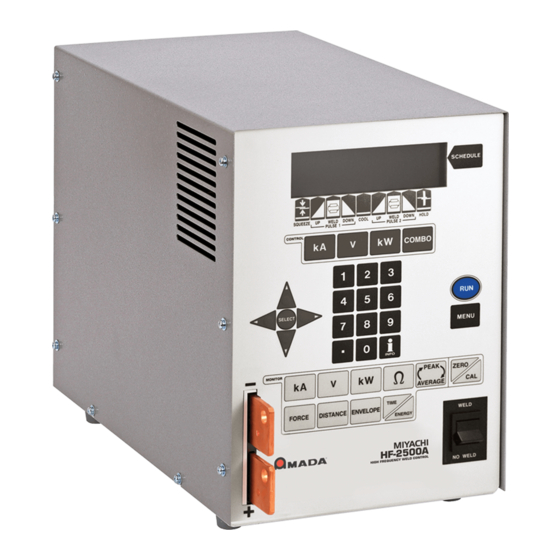
The front panel of the Power Supply below shows controls and indicators. The function of each item is described on the following pages. SCHEDULE KEY LIQUID CRYSTAL DISPLAY (LCD) WELD PERIOD SELECTOR KEYS CONTROL KEYS KEYPAD MODE KEYS MONITOR KEYS WELD / NO WELD Front Panel Controls HF-2500A HIGH FREQUENCY WELD CONTROL 990-371... -
Page 19: Display
Display Controls There are three display control functions: • Selector Key SCHEDULE • Weld Period Selector Keys • Time/Energy Selector Keys HF-2500A HIGH FREQUENCY WELD CONTROL 990-371... -
Page 20: Front Panel Data Entry And Mode Keys
• Enter or modify weld period time and energy values • Enter or modify monitor and limit values • Directly recall a specific weld schedule. To use the numeric keypad, you must first select a time/energy weld period key or the schedule key. HF-2500A HIGH FREQUENCY WELD CONTROL 990-371... -
Page 21: Menu Key
Monitor Keys These keys allow you to view the results of the last weld and to set the limits of the welding parameters beyond which the energy limits monitor terminate the weld and/or initiate alarms. HF-2500A HIGH FREQUENCY WELD CONTROL 990-371... -
Page 22: Weld/No Weld
Power Supply), operate the switch to immediately stop the welding process. All power to the air valves and power circuits will be disconnected. To restart the Power Supply, you must press the RUN key on the front panel. HF-2500A HIGH FREQUENCY WELD CONTROL 990-371... -
Page 23: Chapter 2. Installation And Setup Section I: Installation
Verify that the Power Supply shows no signs of damage. If it does, please contact the carrier. Also, contact AMADA WELD TECH Customer Service immediately at the postal or e-mail address or telephone or FAX number shown in the Foreword of this manual. -
Page 24: Utilities
330-095 HF-2500A/480 3.15 330-097 Compressed Air and Cooling Water If you require compressed air and cooling water service for the weld head, please refer to the weld head manufacturer’s user’s manual for service specifications. HF-2500A HIGH FREQUENCY WELD CONTROL 990-371... -
Page 25: Section Ii: Setup
The pre-wired Configuration Plug above is colored red for clarity, actual color may vary. This plug allows the use of AMADA WELD TECH standard foot switches and weld heads without further configuration. The Power Supply requires configuration of the I/O’s to accept any inputs. -
Page 26: Weld Head Connections
Attach the voltage sensing cable connector to the connector. VOLTAGE SENSE INPUT Install electrodes in the weld head electrode holders. NOTE: If you need additional information about the weld heads, please refer to their user’s manuals. HF-2500A HIGH FREQUENCY WELD CONTROL 990-371... - Page 27 NOTE: Do not attach the firing switch, foot switch or cables EMERGENCY STOP at this time. HF-2500A HIGH FREQUENCY WELD CONTROL 990-371...
-
Page 28: Foot Pedal-Actuated Weld Head Connection
Power Supply cannot deliver weld energy, but the firing switch connection can be verified. 5. Set the circuit breaker on the rear panel of the Power Supply to the ON position. The default screen will be displayed. You will use this screen to enter welding parameters. HF-2500A HIGH FREQUENCY WELD CONTROL 990-371... -
Page 29: Ez-Air Weld Head Connections
CHAPTER 2: INSTALLATION AND SETUP EZ-AIR Weld Head Connections AC EZ-AIR Weld Head Connection HF-2500A HIGH FREQUENCY WELD CONTROL 990-371... - Page 30 This switch, when operated (open), will immediately stop the weld cycle and retract the weld head. See Appendix B. Electrical and Data Connections for circuit details. Connect a Model FS2L or FS1L Foot Switch to the Power Supply connector. FOOT SWITCH HF-2500A HIGH FREQUENCY WELD CONTROL 990-371...
- Page 31 DOWN position, and send the firing switch signal back to the Power Supply when the preset electrode force is reached. The upper electrode should then ascend smoothly back to the UP position. HF-2500A HIGH FREQUENCY WELD CONTROL 990-371...
-
Page 32: Non-Ez-Air Weld Head Connections
Non-EZ-AIR Weld Head Connections Non-EZ-AIR heads may be connected to the Power Supply as shown below, however you should refer to the manual provided with the weld head you are using for specific instructions. HF-2500A HIGH FREQUENCY WELD CONTROL 2-10 990-371... -
Page 33: Chapter 3. System Configuration
SETUP 1 1. FOOTSWITCH WELD ABORT 2. SWITCH DEBOUNCE TIME 10 ms screen is shown on the right with SETUP 1 3. FIRING SWITCH AUTO typical settings. Number Select an item, Page, RUN or MENU HF-2500A HIGH FREQUENCY WELD CONTROL 990-371... -
Page 34: Weld Counter
5. If you accidentally reset the wrong counter, press the period (.) key. The original count will reappear. Press the key to return to the MENU MAIN MENU NUMBER Change, [.] Restore, Page, MENU screen. HF-2500A HIGH FREQUENCY WELD CONTROL 990-371... -
Page 35: Copy A Schedule
SYSTEM SECURITY 1. SCHEDULE LOCK 2. SYSTEM LOCK can protect the weld schedules from unauthorized 3. CALIBRATION changes by programming the Power Supply with a user-defined protection code. NUMBERS Select an item, RUN or MENU HF-2500A HIGH FREQUENCY WELD CONTROL 990-371... -
Page 36: Schedule Lock
SCHEDULE LOCK: OFF 4. If you forget the security code and wish to unlock the Power Supply from security protection: • Return to the screen. CHANGE STATUS • Enter a security code of HF-2500A HIGH FREQUENCY WELD CONTROL 990-371... -
Page 37: Communication
Power Supply will send weld data only when requested by the host CLIENT computer. You must use this role for RS-485 installations with mulitple controls on one communications channel. Press to return to the MENU MAIN MENU HF-2500A HIGH FREQUENCY WELD CONTROL 990-371... - Page 38 I.D. NUMBER 4. Press the key to get the menu screen. This time the line MENU COMMUNICATION I.D. NUMBER will display your I.D. number entry. Press to return to the MENU MAIN MENU. HF-2500A HIGH FREQUENCY WELD CONTROL 990-371...
-
Page 39: Relay
) screen RELAY 1, 2, 3, with a new option, number . Press access the next level menus which are Number Select, Page, RUN or MENU shown on the next page. HF-2500A HIGH FREQUENCY WELD CONTROL 990-371... -
Page 40: Reset To Defaults
Number Select, Page, RUN or MENU 2. Press the key to select . This will automatically reset the system to the factory and return the screen to the display. RESET TO DEFAULTS HF-2500A HIGH FREQUENCY WELD CONTROL 990-371... -
Page 41: Reset All Schedules
In this chain, will just keep repeating after the 100 welds made using Schedule 02 Schedule 01 When the electrodes are replaced or resurfaced, you can manually switch back to Schedule 01 restart the sequence. HF-2500A HIGH FREQUENCY WELD CONTROL 990-371... - Page 42 Use the key to move the SCHEDULE 0002 0001 highlight horizontally back to the WELD 0001 column. Repeat Steps 4 through COUNT 8 to program the rest of the chain. Scroll, SCHEDULE Select, MENU HF-2500A HIGH FREQUENCY WELD CONTROL 3-10 990-371...
-
Page 43: Setup 1
10, 20, or 30 milliseconds before the weld period can be initiated, thereby avoiding false starts caused by the switch contact bouncing. HF-2500A HIGH FREQUENCY WELD CONTROL 990-371 3-11... -
Page 44: Firing Switch
NONE represents a debounce time of 0 ms. Number Select, Page, RUN or MENU for interfacing with the AMADA WELD TECH SL-320A Electronic Weld Force NONE Control. 3. The line will now reflect your switch debounce time selection. SWITCH DEBOUNCE TIME 3. -
Page 45: Setup 2
The weld graph is useful for detecting weld splash, which is indicated by vertical gaps in the overlap. You can reduce weld splash, and eliminate it in some cases, by using the upslope weld energy profile. HF-2500A HIGH FREQUENCY WELD CONTROL 990-371 3-13... -
Page 46: Language
The user will be prompted to choose if a test weld is done or not upon the following conditions: • The voltage level changes • The time in any element of the schedule changes • If the weld energy field is highlighted and the key is pressed. HF-2500A HIGH FREQUENCY WELD CONTROL 3-14 990-371... -
Page 47: Section Iii. Operational States
After making one weld, the Power Supply internally optimizes the feedback control loop to produce the fastest rise time, minimum overshoot weld pulse. state is automatically TEST replaced by the run state for subsequent welds. HF-2500A HIGH FREQUENCY WELD CONTROL 990-371 3-15... -
Page 48: Run State
Use the weld period selector keys to enable the weld periods for programming, and use the numeric pad keys for entering time values in milliseconds. See Chapter 5, Operating Instructions for application-related descriptions of the weld schedule profile. HF-2500A HIGH FREQUENCY WELD CONTROL 3-16 990-371... -
Page 49: Weld State
STOP WELD: The display shows the actual trace of the weld current, voltage or power, and either the peak or the average value for each weld pulse as selected by pressing the key. PEAK/AVERAGE HF-2500A HIGH FREQUENCY WELD CONTROL 990-371 3-17... -
Page 50: Alarm State
The example WELD alarm screen SWITCH IN NO WELD POSITION shown at the right is displayed when you attempt to initiate a weld with the switch WELD/ NO WELD in the position. NO WELD HF-2500A HIGH FREQUENCY WELD CONTROL 3-18 990-371... -
Page 51: Section Iv. Weld Functions
Weld round parts, parts that are not flat, spring steel parts, or heavily plated or oxidized parts Up/Downslope such as aluminum. Dual Pulse Use for best control of miniature and small parts spot welding with or without plating. HF-2500A HIGH FREQUENCY WELD CONTROL 990-371 3-19... -
Page 52: Weld Head Applicability
CHAPTER 3: SYSTEM CONFIGURATION Weld Head Applicability The weld functions can be used with AMADA WELD TECH force fired, manual weld heads; air actuated weld heads; or SL-300A Weld Heads. is used to allow sufficient time for the electrodes SQUEEZE TIME to close and apply the required weld force to the parts before the weld current begins. -
Page 53: Weld Schedule Definition
Weld Pulse 2, Downslope 2, and Hold Time. The sample dual-pulse profile [or waveform] below shows the weld current and the corresponding position of the weld head. The graph labeled WELD CURRENT what displays on the LCD when you schedule a weld profile. Sample Weld Sequence (Dual-Pulse) HF-2500A HIGH FREQUENCY WELD CONTROL 990-371 3-21... -
Page 54: Welding Applications
Flat parts that do not have any plating or heavy oxides. Conductive parts made of copper or brass. Description Single-Pulse is a term used by the industry to describe the simplest heat profile used for many resistance spot-welding applications. Single-Pulse Weld Profile HF-2500A HIGH FREQUENCY WELD CONTROL 3-22 990-371... -
Page 55: Upslope/Downslope Weld Profile
Round-to-flat small parts that may or may not be plated. Description Adding upslope to the front of both weld periods allows a reduction in electrode force, this results in a cleaner appearance by reducing electrode indentation, material pickup and electrode deformation. HF-2500A HIGH FREQUENCY WELD CONTROL 990-371 3-23... - Page 56 Experiment with upper and lower limit values that you can use to inhibit the Pulse 2 weld if the test conditions measured by the Pulse 1 weld are out of limits. NOTE: Upslope is required when a lower limit value is programmed. HF-2500A HIGH FREQUENCY WELD CONTROL 3-24 990-371...
-
Page 57: Chapter 4. Introduction To Feedback Modes And Monitoring
This mode precisely varies the weld current and voltage to supply consistent weld energy to the parts. The power mode has been shown to extend electrode life in automated applications. Set monitoring limits on current or voltage. HF-2500A HIGH FREQUENCY WELD CONTROL 990-371... -
Page 58: Section Ii. Weld Monitoring
When you press the key, PEAK AVERAGE the top line in the LCD simply toggles back and forth so you can view either PEAK values whenever you choose. AVERAGE HF-2500A HIGH FREQUENCY WELD CONTROL 990-371... -
Page 59: Current, Voltage, Power, And Resistance Limits
In order for a weld to occur, the surface oxides and contamination must be displaced to allow proper current flow through the parts. Levels of oxide and contamination vary from part to part over time, which can have an adverse effect on the consistency of the welding process. HF-2500A HIGH FREQUENCY WELD CONTROL 990-371... - Page 60 The purpose of a dual-pulse operation is to enable the first pulse to target displacement of oxides and good fit up; the second pulse achieves the weld. HF-2500A HIGH FREQUENCY WELD CONTROL 990-371...
- Page 61 The purpose of a dual-pulse operation is to enable the first pulse to target variations in resistance; the second pulse achieves the weld. Resistance Set Waveform HF-2500A HIGH FREQUENCY WELD CONTROL 990-371...
- Page 62 In addition to inhibiting the weld, the Power Supply has four programmable relay outputs, which can be used to trigger alarms to signal operators of weld faults or signal automation equipment to perform pre- programmed actions, such as stopping the assembly line so the faulty weld piece can be removed. HF-2500A HIGH FREQUENCY WELD CONTROL 990-371...
- Page 63 For example: • If you are welding in constant current, monitor voltage. • If you are welding in constant voltage, monitor current. • If you are welding in constant power, monitor current or voltage. HF-2500A HIGH FREQUENCY WELD CONTROL 990-371...
- Page 64 For example: • If you are welding in constant current, monitor voltage. • If you are welding in constant voltage, monitor current. • If you are welding in constant power, monitor current or voltage. HF-2500A HIGH FREQUENCY WELD CONTROL 990-371...
- Page 65 If you are using an air-actuated weld head, verify that compressed air is connected as described in the appropriate sections of your weld head manual. Turn the compressed air ON, and adjust it according to the instructions in your weld head manual. HF-2500A HIGH FREQUENCY WELD CONTROL 990-371...
- Page 66 3. Turn the switch on the rear panel of the Power Supply to the position. The default ON/OFF screen will be displayed. You will use this screen to enter welding parameters. Default RUN Screen HF-2500A HIGH FREQUENCY WELD CONTROL 990-371...
- Page 67 Use the numeric keypad or the ▲▼ arrows. Enter milliseconds. Note that in combo mode when the unit reaches a constant current, any time programmed in this segment will be added to the weld at the constant current level. HF-2500A HIGH FREQUENCY WELD CONTROL 990-371...
- Page 68 Use HOLD the numeric keypad or the ▲▼ arrows. Enter a time between milliseconds. We recommend at least 50 milliseconds as weld strength is formed in the hold time. HF-2500A HIGH FREQUENCY WELD CONTROL 990-371...
- Page 69 A good starting point is 5 milliseconds. Note that in combo mode when the unit reaches a constant current, any time programmed in this segment will be added to the weld at the constant current level. HF-2500A HIGH FREQUENCY WELD CONTROL 990-371...
- Page 70 Use HOLD the numeric keypad or the arrows. Enter a time between 0 and 999 milliseconds. We recommend at least milliseconds as weld strength is formed in the hold time. HF-2500A HIGH FREQUENCY WELD CONTROL 990-371...
- Page 71 Use the numeric keypad to enter the time or use the ▲▼ arrows. Enter a time between milliseconds. Note that in combo mode when the unit reaches a constant current, any time programmed in this segment will be added to the weld at the constant current level. HF-2500A HIGH FREQUENCY WELD CONTROL 990-371...
- Page 72 Use HOLD the numeric keypad to enter the time or use the ▲▼ arrows. Enter a time between milliseconds. We recommend at least milliseconds. HF-2500A HIGH FREQUENCY WELD CONTROL 990-371...
- Page 73 For some welds it may be very important to get up to the peak voltage or current to get the right melting and get there at the right time during the pulse. Every millisecond could be very important. HF-2500A HIGH FREQUENCY WELD CONTROL 990-371...
- Page 74 • stops the weld at the end of Pulse 1, and prevents Pulse 2 from firing. INHIBIT PULSE 2 This function will not operate if both pulses are joined without a cool time. HF-2500A HIGH FREQUENCY WELD CONTROL 5-10 990-371...
- Page 75 If this is not done, the last input field will remain highlighted, and the changes will not be saved to memory. Any welds done in this condition will use the older, unedited values still stored in the memory. HF-2500A HIGH FREQUENCY WELD CONTROL 990-371 5-11...
- Page 76 Repeat steps 1 → 10 until the limits are where you want them. NOTE: Lower limits apply to the programmed weld time only. Programming a longer upslope extends the time before a lower limit applies in the monitoring screen. HF-2500A HIGH FREQUENCY WELD CONTROL 5-12 990-371...
- Page 77 (usually double the time works). This will ensure that there will be enough time for the current to rise and reach the limit, even with heavily oxidized parts. HF-2500A HIGH FREQUENCY WELD CONTROL 990-371 5-13...
- Page 78 Constant voltage is recommended for round parts and constant current for flat parts. An upslope may be required to restrict the current flow early in the second pulse and avoid weld splash. HF-2500A HIGH FREQUENCY WELD CONTROL 5-14 990-371...
-
Page 79: Resistance Set
PULSE 1 1. none 2. STOP WELD screen. OUT OF LIMITS ACTION 3. INHIBIT PULSE 2 4. PART CONDITIONER (Stop Pulse1) Select 4. PART CONDITIONER (Stop PULSE1). NUMBER Select Page, RUN or MENU HF-2500A HIGH FREQUENCY WELD CONTROL 990-371 5-15... - Page 80 Constant voltage is recommended for round parts and constant current for flat parts. An upslope may be required to restrict the current flow early in the second pulse and avoid weld splash. HF-2500A HIGH FREQUENCY WELD CONTROL 5-16 990-371...
-
Page 81: Pre-Weld Check
Return to the screen and make several welds. Observe that under normal conditions, the welds are not aborted, and that consistent, strong welds can be produced. HF-2500A HIGH FREQUENCY WELD CONTROL 990-371 5-17... - Page 82 Pulse 1 current from the RUN screen if needed to optimize the Pre-Weld Check settings. The Pre-Weld Check function can now be used to detect misaligned or missing parts before the Pulse 2 welding current is delivered to the parts. Pre-Weld Check Waveform HF-2500A HIGH FREQUENCY WELD CONTROL 5-18 990-371...
- Page 83 This will bring up the PULSE 1 1. none 2. STOP WELD screen. OUT OF LIMITS ACTION 3. INHIBIT PULSE 2 4. PART CONDITIONER (Stop Pulse1) Select 2. STOP WELD NUMBER Select, Page, RUN or MENU HF-2500A HIGH FREQUENCY WELD CONTROL 990-371 5-19...
- Page 84 If you are welding in constant current, put limits on voltage. • If you are welding in constant voltage, put limits on current. • If you are welding in constant power, put limits on current or voltage. HF-2500A HIGH FREQUENCY WELD CONTROL 5-20 990-371...
-
Page 85: Section Viii. Weld Stop
Toggle the Pulse 1 weld key to highlight the lower limit field for the Pulse 1 weld period. Use the numeric keypad to enter a lower limit value with a voltage level that is slightly lower than the voltages observed in step 3 above. HF-2500A HIGH FREQUENCY WELD CONTROL 990-371 5-21... - Page 86 If you are welding in constant current, put limits on voltage. • If you are welding in constant voltage, put limits on current. • If you are welding in constant power, put limits on current or voltage. HF-2500A HIGH FREQUENCY WELD CONTROL 5-22 990-371...
-
Page 87: Section Ix. Programming Relays
) screen RELAY 1, 2, 3, with a new option, number . Press access the next level menus which are Number Select, Page, RUN or MENU shown on the next page. HF-2500A HIGH FREQUENCY WELD CONTROL 990-371 5-23... -
Page 89: Chapter 6. Maintenance
These messages will usually let you know what action is required of you to correct the reason for the alarm. For a complete listing of the alarm messages, what they mean, and corrective actions, see Section II, Troubleshooting. HF-2500A HIGH FREQUENCY WELD CONTROL 990-371... -
Page 90: Section Ii. Troubleshooting
1. Incompatible weld piece projection 1. Wrong electrode tip shape Electrode Electrode design Damage 2. Excessive weld time set at HF-2500A Sparking 1. Contaminated weld piece surface/ plating 2. Contaminated weld piece surface/ 1. Wrong electrode tip shape plating 2. Wrong electrode material 2. -
Page 91: Alarm Messages
Problem Cause (in order of probability) Problem Cause (in order of probability) 1. Excessive weld time set at HF-2500A 1. Excessive weld time set at HF-2500A 1. No cover gas on weld piece 2. Excessive current/energy set at HF- 2. Excessive current/energy set at HF-... - Page 92 Reset the Upper Limit for Weld1 to a larger value. user set Upper Limit value for Weld1. UPPER LIMIT While in the voltage or power feedback mode, the HF-2500A could not control ENERGY SETTING the energy setting because the required Increase the energy setting.
- Page 93 RESISTANCE TOO capability of the HF-2500A. HIGH Check cable and weld head connections. The HF-2500A will not be able to Verify that all three phases from the input power maintain the user set weld parameters. lines are functioning Replace the memory battery on the Main Control The battery supplying backup power to PCB.
- Page 94 Lower Limit value for Weld2. LIMIT Reset the Lower Limit for Weld2 to a smaller value. POWER The power dissipated by the power Reduce duty cycle. TRANSISTOR transistors has exceeded the HF-2500A Reduce weld time. OVERHEATED specified capability. Process Stop signal PROCESS STOP ON...
- Page 95 If the terminated weld energy is not adequate for the weld, re-set the Upper Limit values for Weld1 and Weld2. User has tried to activate the HF-2500A WELD SWITCH IN with the Weld/No Weld Switch in the No Set the Weld/No Weld switch to the Weld NO WELD Weld Position.
-
Page 96: Section Iii. Maintenance
If you have problems with your Power Supply that you cannot resolve, please contact our service department at the address, phone number, or e-mail address indicated in in the front of this CONTACT US manual. HF-2500A HIGH FREQUENCY WELD CONTROL 990-371... -
Page 97: Appendix A. Technical Specifications
Power Input Power Line ....................50-60 Hz, 3 phase Input Voltage Range at Maximum Output Current HF-2500A/240 ....................192-264 VAC at 25 A HF-2500A/400 ....................320-440 VAC at 20 A HF-2500A/480 ....................384-528 VAC at 13 A Input kVA (Demand) ................30 kVA max at 3% duty cycle Output Power at 12% Duty Cycle and a Combined PULSE 1 and PULSE 2 Pulse Width of 50 ms ........ - Page 98 ± (2% of setting +0.02 V) Power 0.05 - 9.999 kW ± (5% of setting +10 W) Limit Ranges: Same as the measurement ranges Alarms: Display alert and four programmable AC/DC relay contact outputs. HF-2500A HIGH FREQUENCY WELD CONTROL 990-371...
- Page 99 Monitor: Internal analog voltage signals representing secondary current feedback (0 - 5 VDC), primary current (0 - 4 VDC), or weld voltage (0 - 5VDC). Air Valve Driver: 24 VAC, 1 amp; timing controlled by the HF-2500A. No weld over-force protection.
- Page 100 ...
-
Page 101: Appendix B. Electrical And Data Connections
Be sure that the shop source power is appropriate for your Power Supply model. • If the blue phase wire is not connected, no alarm will occur and the weld control will produce more than 20% ripple in the weld output waveform. HF-2500A HIGH FREQUENCY WELD CONTROL 990-371... - Page 102 10-pin plugs, including the factory-supplied Configuration Plug Selected pins contain red inserts as shown below. These inserts prevent properly configured 10-pin plugs from being plugged into the wrong sections of the 60-pin connector. HF-2500A HIGH FREQUENCY WELD CONTROL 990-371...
- Page 103 , you must remove the tabs for pins , and . If 31 - 40 you do not remove the appropriate tabs, you will not be able to insert the plug into the Power Supply. HF-2500A HIGH FREQUENCY WELD CONTROL 990-371...
- Page 104 11 through 20. It allows the use of standard AMADA WELD TECH foot switches and weld heads without further configuration. For other configuration methods please refer to Modification of I/O Configuration on page B-6.
- Page 105 APPENDIX B: ELECTRICAL AND DATA CONNECTIONS I/O Signal Interface General Description HF-2500A HIGH FREQUENCY WELD CONTROL 990-371...
- Page 106 COMMON terminal for pins 10, 13, 24 - 31 24COM NEGATIVE of internal 24 VDC power supply SCHEDULE 0 SCHEDULE 1 SCHEDULE 2 SCHEDULE 4 Binary Schedule input terminals, used for schedule selection SCHEDULE 8 SCHEDULE 16 SCHEDULE 32 WELD_INHIBIT Inhibits weld HF-2500A HIGH FREQUENCY WELD CONTROL 990-371...
- Page 107 Relay 3 output, dry contact, programmable Contact rating: 24 VDC/AC, 1 amp RELAY_3R RELAY_4 Relay 4 output, dry contact, programmable Contact rating: 24 VDC/AC, 1 amp RELAY_4R 41-59 Not Active Not active CHASSIS GROUND Chassis ground HF-2500A HIGH FREQUENCY WELD CONTROL 990-371...
- Page 108 SCHEDULE 2 (2 I/O COMMON SCHEDULE 4 (2 SCHEDULE 8 (2 SCHEDULE 16 (2 SCHEDULE 32 (2 WELD INHIBIT FOOT SWITCH / FIRE SWITCH INPUTS Common Inputs Pin Number FIRE_1 FOOT_1 FS1/FS2/FIRE_COM FOOT_2 CURRENT STOP HF-2500A HIGH FREQUENCY WELD CONTROL 990-371...
- Page 109 Configuration for Common Input Connections: Dry Contact Input Common Positive Input (External Power) Common Negative Input Common Positive Input (External Power) (Internal Power) NOTE: The preceding configuration methods can be used for both input blocks. HF-2500A HIGH FREQUENCY WELD CONTROL 990-371...
- Page 110 UP position. Using the supplied Configuration plug on Pins 11 – 20 allows the use of the AMADA WELD TECH 2- level footswitch directly. If a PLC or other means of trigger is used, refer to the I/O Signal Interface General Description on page B-3.
- Page 111 AIR AMADA WELD TECH weld head. Using the supplied Configuration plug on Pins 11 – 20 allows the use of the AMADA WELD TECH 2- level footswitch directly. If PLC or other means of trigger is used, refer to the I/O Signal Interface General Description on page B-3.
- Page 112 Connect an approved, normally closed emergency stop switch across the 2 foot (61 cm) operator emergency stop switch cable. When the switch is operated (opened), it de-energizes the main power contactor, removing three-phase input power to the Power Supply. HF-2500A HIGH FREQUENCY WELD CONTROL B-12 990-371...
- Page 113 Bit 2 Bit 2 Bit 2 Bit 2 Bit 2 Bit 2 Schedule Sch 0 Sch 1 Sch 2 Sch 4 Sch 8 Sch 16 Sch 32 5-98 BCD progression from 5 to 98 HF-2500A HIGH FREQUENCY WELD CONTROL 990-371 B-13...
- Page 114 Relay contacts closed or open in the energized state. Relays are energized when: 1. Weld cycle starts. 2. Weld cycle ends. 3. Alarm state is detected. 4. Weld is out of programmed limits. HF-2500A HIGH FREQUENCY WELD CONTROL B-14 990-371...
-
Page 115: Appendix C. Calibration
• Shielded voltage sense cable, Pt # 4-32998-01 • Digital oscilloscope, Tektronix 724C or equivalent • Male BNC to dual binding post • 2-wire, normally open switch for weld initiation, mating connector Pt # 520-001 • Coaxial BNC-to-BNC cable HF-2500A HIGH FREQUENCY WELD CONTROL 990-371... - Page 116 REFER TO MANUAL FOR CALIBRATION SETUP. ▼ next, MENU 5. Press to calibrate the HF-2500A. <PRE-CALIBRATION> 1. TEST HF25 (T-232 REQUIRED) 2. CALIBRATE HF25 3. RESET CALIBRATION 4. SET CURRENT SHUNT VALUE 5. TEST SERIAL PORT Menu HF-2500A HIGH FREQUENCY WELD CONTROL 990-371...
- Page 117 BNC to binding post adapter and voltage sense cable. Follow the screen instructions for this step and the next step, 4. CALIBRATION LOW Final Calibration Setup 10. The last calibration screen is Press the key. HF-2500A 5. END OF CALIBRATION. MENU calibration is now complete. HF-2500A HIGH FREQUENCY WELD CONTROL 990-371...
-
Page 119: Appendix D. System Timing
APPENDIX D System Timing Basic Weld Operation: Air Head System with Two-Level Foot Switch NOTE: The feature is not available on the HF-2500A SOFT TOUCH PRESSURE Power Supply, it is only available on HF-2700A Power Supply. Definitions Delay time from Foot Switch Level 1 closure to Weld Force start. Maximum delay time is 1 ms plus switch debounce time. - Page 120 Weld time. Selectable range is 0.0 to 99.0 ms. DOWN Down slope time. Selectable range is 0.0 to 99.0 ms. Cool time. Selectable range is 0.0 to 99.0 ms. COOL Hold time. Selectable range is 0 to 999 ms. HOLD HF-2500A HIGH FREQUENCY WELD CONTROL 990-371...
- Page 121 Weld time. Selectable range is 0.0 to 99.0 ms. WELD DOWN Down slope time. Selectable range is 0.0 to 99.0 ms. COOL Cool time. Selectable range is 0.0 to 99.0 ms. HOLD Hold time. Selectable range is 0 to 999 ms. HF-2500A HIGH FREQUENCY WELD CONTROL 990-371...
- Page 122 APPENDIX D: SYSTEM TIMING Basic Weld Operation: Air Head System with Two-Level Foot Switch NOTE: The feature is not available on the HF-2500A SOFT TOUCH PRESSURE Power Supply, it is only available on HF-2700A Power Supply. Definitions Delay time from Foot Switch Level 1 closure to Weld Force start. Maximum delay time is 1 ms plus switch debounce time.
-
Page 123: Appendix E. Communications
A terminating resistor assembly is supplied with the unit. If only one unit is connected to the host, the terminating resistor assembly must be installed in that unit. If multiple units are connected to the host, only one unit (the unit furthest from the host) must have the terminating resistor assembly installed. HF-2500A HIGH FREQUENCY WELD CONTROL 990-371... - Page 124 ME, Windows 2000, Windows XP or Windows NT 4.0. For a hardware-based converter without an internal microprocessor (such as the Telebyte model 285), the host computer should be at least a Pentium III-550 running Windows 98, Windows ME, Windows 2000, Windows XP or Windows NT 4.0. HF-2500A HIGH FREQUENCY WELD CONTROL 990-371...
- Page 125 Several commands require the unit to be in mode for the unit to accept them. Those commands HOST include the command and all commands. See the command in Chapter 3 and REPORT HOST CNTL command below for more information. REMOTE HF-2500A HIGH FREQUENCY WELD CONTROL 990-371...
- Page 126 TERMINATION OF COMMAND: <lf> (linefeed - must be preceded by the end of line terminator <crlf>). Each unit identifier, command keyword, and parameters must be separated by one or more spaces except the termination of command <lf> must follow the end of parameter terminator<crlf> immediately. I. E. “<crlf><lf>” HF-2500A HIGH FREQUENCY WELD CONTROL 990-371...
- Page 127 POWER <crlf><lf> Control State Description Requests the Power Supply to report the sampled Power data of the last weld. Power Supply shall return with POWER report. See POWER command under Power Supply Originating Commands section. HF-2500A HIGH FREQUENCY WELD CONTROL 990-371...
- Page 128 If the number is greater than the number of weld data in the buffer, less than the number of weld data will be sent. NOTE: There must be at least one space between each of the three field. HF-2500A HIGH FREQUENCY WELD CONTROL 990-371...
- Page 129 0.01 for increments from 0.1 to 0.99 ms and increments of 0.1 ms for 1.0 to 9.9 ms and increments of 1.0 ms for 10.0 to 99.0 ms. (see table next page) HF-2500A HIGH FREQUENCY WELD CONTROL 990-371...
- Page 130 Lower Limit P1LDLY2 {delay_value} Pulse 1 Lower Delay End Time For Lower Limit P1UDLY1 {delay_value} Pulse 1 Upper Delay Start Time For Upper Limit P1UDLY2 {delay_value} Pulse 1 Upper Delay End Time For Upper Limit HF-2500A HIGH FREQUENCY WELD CONTROL 990-371...
- Page 131 { ALARM | LIMITS | WELD | END | P1HI | P1LOW | P2HI | P2LOW | MG3 } NOTE: extended_condition_value: P1HI, P1LOW: Pulse 1 hi/low limit reached. P2HI, P2LOW: Pulse 2 hi/low limit reached. HF-2500A HIGH FREQUENCY WELD CONTROL 990-371...
- Page 132 0 to 100 for buzzer loudness. 0 is off and 100 is the loudest. switch _state: { MECHOPEN | MECHCLOSED | OPTOOPEN | OPTOCLOSED | PLC0V | PLC24V} HF-2500A HIGH FREQUENCY WELD CONTROL E-10 990-371...
- Page 133 Allows control of the system security mode. “OFF” sets all security status Power Supply to “OFF.” “SCHEDULE” sets the schedule lock to “ON.” “SYSTEM” sets the system lock to “ON.” “CALIBRATION” sets the calibration lock to “ON.” HF-2500A HIGH FREQUENCY WELD CONTROL 990-371 E-11...
- Page 134 Command TYPE type, release numbers, revision letters<crlf><lf> Control State Description Returns “HF25 1.00 A 37250” for the first release of an HF-2500A. Command COUNT number <crlf><lf> Control State Description Returns the number of weld data available in Power Supply. The total number of weld data that the Power Supply holds in the buffer is 900.
- Page 135 Power Supply samples Current and Voltage every 40 µs. For a weld less than 80 ms weld µ time, the number of data will be approximately: total weld time ÷ 40 s. This number will be always less than 2000. data: An integer number in unit of W. HF-2500A HIGH FREQUENCY WELD CONTROL 990-371 E-13...
- Page 136 0 to 99 for brightness of the LCD. 0 is dark and 100 is the brightest. loudness_value is a number 0 to 99 for buzzer loudness. 0 is off and 100 is the loudest. switch_state: { MECHOPEN | MECHCLOSED | OPTOOPEN | OPTOCLOSED | PLC0V | PLC24V} HF-2500A HIGH FREQUENCY WELD CONTROL E-14 990-371...
- Page 137 The average resistance of pulse 2 (in 10 Ω). peak_resistance_2: The peak resistance of pulse 2 (in 10 null_3: Always zero null_4: Always zero Weld_count: The number of this weld assigned by the unit HF-2500A HIGH FREQUENCY WELD CONTROL 990-371 E-15...
- Page 138 CHAINED TO NEXT SCHEDULE SAFE ENERGY LIMIT REACHED P1 LOWER LIMIT DELAYS ADJUSTED P1 UPPER LIMIT DELAYS ADJUSTED P2 LOWER LIMIT DELAYS ADJUSTED P2 UPPER LIMIT DELAYS ADJUSTED UPSLOPE REQUIRED FOR LOWER LIMIT HF-2500A HIGH FREQUENCY WELD CONTROL E-16 990-371...
- Page 139 CURRENT1 > UPPER LIMIT CURRENT1 < LOWER LIMIT VOLTAGE1 > UPPER LIMIT VOLTAGE1 < LOWER LIMIT POWER1 > UPPER LIMIT POWER1 < LOWER LIMIT RESISTANCE1 > UPPER LIMIT RESISTANCE1 < LOWER LIMIT NOT USED NOT USED HF-2500A HIGH FREQUENCY WELD CONTROL 990-371 E-17...
- Page 140 NOT USED NOT USED NOT USED NOT USED NOT USED Command SCHEDULE schedule_number <crlf><lf> Control State Description Returns the current schedule number to the host. Schedule_number may be any number from 0 to 99. HF-2500A HIGH FREQUENCY WELD CONTROL E-18 990-371...
- Page 141 Increments Range Time Range Increments 0.01 0.1 - 0.99 0.1 - 0.99 ms 0.01 ms 1.00 - 9.90 1.0 - 9.9 ms 0.1 ms 10.00 - 99.0 10.0 - 99.0 ms 1 ms HF-2500A HIGH FREQUENCY WELD CONTROL 990-371 E-19...
- Page 142 HF-2500A model and the load resistance). • Power Feedback mode: weld_energy for the HF-2500A is in units of 1 W, and the range is from 10 W to 9900 W (10 to 9900). volt multiplier is the index value for a table of resistance vs. a PID multiplier for voltage mode (used for the last weld).
- Page 143 Reports the relay settings. Command SECURITY<crlf> SCHEDULE { ON | OFF }<crlf> SYSTEM { ON | OFF }<crlf> CALIBRATION { ON | OFF }<crlf><lf> Control State Description Returns the current status of the security settings. HF-2500A HIGH FREQUENCY WELD CONTROL 990-371 E-21...
-
Page 145: Appendix F. The Basics Of Resistance Welding
The formula for amount of heat generated is I RT -- the square of the weld current [ I ] times the workpiece resistance [ R ] times the weld time [ T ]. Welding Parameter Interaction Interaction of Welding Parameters HF-2500A HIGH FREQUENCY WELD CONTROL 990-371... - Page 146 Brass -2, -14 Brass -2, -14 Stainless Steel Copper Beryllium Copper Bronze -2, -11 Bronze -2, -11 Copper Beryllium Tinned Copper Bronze -2, -11 Tinned Copper Copper Beryllium Nickel Bronze -2, -11 Iron Copper HF-2500A HIGH FREQUENCY WELD CONTROL 990-371...
- Page 147 Plate Plate Kovar, Gold Copper Karme Kulgrid Plate Kovar, Gold Copper Manganin Nickel Plate Kovar, Gold Copper Nichrome Silver -11, -14 Plate Kovar, Gold Copper Nickel Stainless Steel Plate Copper Paliney 7 Magnesium Magnesium HF-2500A HIGH FREQUENCY WELD CONTROL 990-371...
- Page 148 If this is not done, the rough surface of the electrode face will have a tendency to stick to the work piece. HF-2500A HIGH FREQUENCY WELD CONTROL 990-371...
- Page 149 Fatigue tests and radiography have also been used. Of these methods torsional shear is preferred for round wire and a 45-degree peel test for sheet stock. HF-2500A HIGH FREQUENCY WELD CONTROL 990-371...
- Page 150 14 lb electrode force curve. A comparison of weld schedules for several different applications might show that they could be consolidated into one or two weld schedules. This would have obvious manufacturing advantages. HF-2500A HIGH FREQUENCY WELD CONTROL 990-371...
-
Page 151: Appendix G. Quality Resistance Welding Solutions: Defining The Optimum Process
Ceramic (alumina, sand) • Plastics/polymers (PVC, teflon) • Semiconductors (silicon, geranium) Of these, only metals can be resistance welded because they are electrically conductive, soften on heating, and can be forged together without breaking. HF-2500A HIGH FREQUENCY WELD CONTROL 990-371... - Page 152 As there is no real melting of the materials in a solid-state joint, there is less chance of weld splash or material expulsion. A weld nugget can still be achieved with a solid-state joint. HF-2500A HIGH FREQUENCY WELD CONTROL 990-371...
- Page 153 Group I – Conductive Metals Conductive metals dissipate heat and it can be difficult to focus heat at the interface. A solid- state joint is therefore preferred. Typically, resistive electrode materials are used to provide additional heating. HF-2500A HIGH FREQUENCY WELD CONTROL 990-371...
- Page 154 Contact Resistance Resistance Bulk Resistance Time The figure above shows the key resistances in a typical opposed resistance weld and the relationship between contact resistances and bulk resistances over time, during a typical resistance weld: HF-2500A HIGH FREQUENCY WELD CONTROL 990-371...
- Page 155 The contact resistances present at the weld when the power supply is fired have a great impact on the heat balance of a weld and, therefore, the heat affected zone. HF-2500A HIGH FREQUENCY WELD CONTROL 990-371...
- Page 156 The stages of heat generation for conductive materials will be similar to that of resistive materials, but there will be less heat generated in the bulk resistance due to the conductivity of the materials. HF-2500A HIGH FREQUENCY WELD CONTROL 990-371...
- Page 157 Power supply technology selection is based on the requirements of both the application and process. In general, closed loop power supply technologies are the best choice for consistent, controlled output and fast response to changes in resistance during the weld. HF-2500A HIGH FREQUENCY WELD CONTROL 990-371...
- Page 158 • Materials: Resistivity, melting point, thermal mass, shape, hardness, surface properties. • Heat balance: Electrode materials, shape, Polarity, heating rate (upslope). • Observation: visual criteria, cross section, and impact of variables on heat balance. HF-2500A HIGH FREQUENCY WELD CONTROL 990-371...
- Page 159 This part of weld development is critical in order to proceed to a statistical method of evaluation (Design of Experiments or “DOEs”). Random explosions or unexpected variables will skew statistical data and waste valuable time. HF-2500A HIGH FREQUENCY WELD CONTROL 990-371...
- Page 160 Screening DOE’s may be required. AMADA WELD TECH provides a simple Screening DOE tool that is run in Excel® and is sufficient for the majority of possible applications (contact AMADA WELD TECH for details). Sophisticated software is also available from other vendors designed specifically for this purpose.
- Page 161 Validation testing is usually required to prove the robustness of the process under production conditions. HF-2500A HIGH FREQUENCY WELD CONTROL 990-371...
- Page 162 Welding problems can more easily be identified and solved if sufficient experimental work is carried out to identify the impact of common variables on the quality and variation of the welded assembly. AMADA WELD TECH frequently uses the Screening DOE tool to establish the impact of key variables and to assist customers with troubleshooting.
- Page 163 TEL. +1-626-303-5676 FAX, +1-626-358-8048 http://www.amadaweldtech.com AMADA WELD TECH CO., LTD. 200, Ishida, Isehara-shi, Kanagawa 259-1196, Japan AMADA WELD TECH KOREA CO., LTD. 28, Dongtanhana 1-gil, Hwaseong-si, Gyeonggi-do, 18423, Korea TEL. +82-31-8015-6810 FAX. +82-31-8003-5995 AMADA WELD TECH SHANGHAI CO., LTD. Unit 401, A206(C8), No. 77, Hongcao Road, Xuhui District, Shanghai, China TEL.
- Page 164 AMADA WELD TECH INC. 1820 South Myrtle Ave., Monrovia, CA 91016, U.S.A. TEL. +1-626-303-5676 FAX. +1-626-358-8048...
Need help?
Do you have a question about the HF-2500A and is the answer not in the manual?
Questions and answers