Table of Contents

Subscribe to Our Youtube Channel
Related Manuals for Future light PHP-21 TCL LED-Head-Effect


Summary of Contents for Future light PHP-21 TCL LED-Head-Effect
- Page 1 BEDIENUNGSANLEITUNG USER MANUAL PHP-21 TCL LED-Head-Effect © Copyright Für weiteren Gebrauch aufbewahren! Nachdruck verboten! Keep this manual for future needs! Reproduction prohibited!
-
Page 2: Table Of Contents
Inhaltsverzeichnis Table of contents EINFÜHRUNG..............................3 Lieferumfang ..............................3 SICHERHEITSHINWEISE..........................4 BESTIMMUNGSGEMÄßE VERWENDUNG..................... 5 GERÄTEBESCHREIBUNG ..........................6 Features ................................. 6 Geräteübersicht.............................. 7 INSTALLATION ..............................8 Projektormontage............................8 Anschluss an den DMX-512 Controller / Verbindung Projektor - Projektor ..........11 Anschluss ans Netz ............................. 12 BEDIENUNG .............................. -
Page 3: Einführung
BEDIENUNGSANLEITUNG PHP-21 TCL LED-Head-Effect Lesen Sie vor der ersten Inbetriebnahme zur eigenen Sicherheit diese Bedienungsanleitung sorgfältig durch! Alle Personen, die mit der Aufstellung, Inbetriebnahme, Bedienung, Wartung und Instandhaltung dieses Gerätes zu tun haben, müssen - entsprechend qualifiziert sein - diese Bedienungsanleitung genau beachten - die Bedienungsanleitung als Teil des Produkts betrachten - die Bedienungsanleitung während der Lebensdauer des Produkts behalten - die Bedienungsanleitung an jeden nachfolgenden Besitzer oder Benutzer des Produkts weitergeben... -
Page 4: Sicherheitshinweise
SICHERHEITSHINWEISE ACHTUNG! Seien Sie besonders vorsichtig beim Umgang mit gefährlicher Netzspannung. Bei die- ser Spannung können Sie einen lebensgefährlichen elektrischen Schlag erhalten! Dieses Gerät hat das Werk in sicherheitstechnisch einwandfreiem Zustand verlassen. Um diesen Zustand zu erhalten und einen gefahrlosen Betrieb sicherzustellen, muss der Anwender die Sicherheitshinweise und die Warnvermerke unbedingt beachten, die in dieser Bedienungsanleitung enthalten sind. -
Page 5: Bestimmungsgemäße Verwendung
Es dürfen unter keinen Umständen Flüssigkeiten aller Art in Steckdosen, Steckverbindungen oder in irgendwelche Geräteöffnungen oder Geräteritzen eindringen. Besteht der Verdacht, dass - auch nur minimale - Flüssigkeit in das Gerät eingedrungen sein könnte, muss das Gerät sofort allpolig vom Netz getrennt werden. -
Page 6: Gerätebeschreibung
- - -m Das Bildzeichen bezeichnet den Mindestabstand zu beleuchteten Gegenständen. Der Abstand zwischen Lichtaustritt und der zu beleuchteten Fläche darf diesen Wert nicht unterschreiten! Das Gerät darf nur auf nicht brennbaren Oberflächen aufgestellt werden. Um eine gute Luftzirkulation zu gewährleisten, muss um das Gerät ein Freiraum von mindestens 50 cm eingehalten werden. -
Page 7: Geräteübersicht
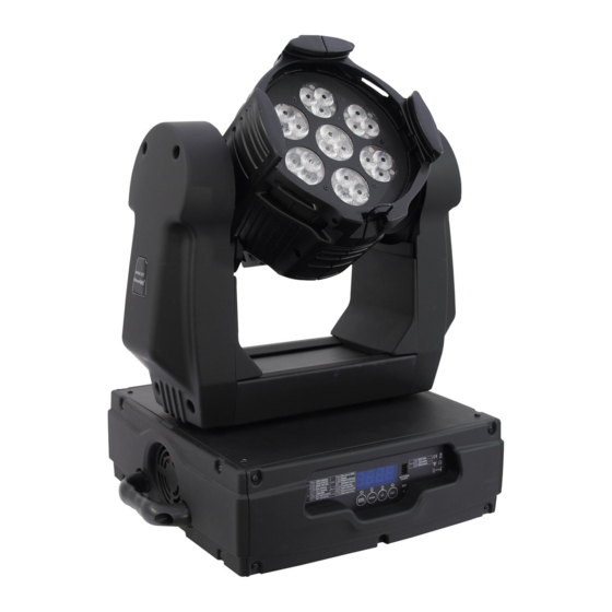
Geräteübersicht (1) Halteklammern (2) Projektorkopf (3) Projektorarm (4) Base (5) Tragegriff (6) Steuereinheit (7) Mode/Enter-Taste (8) Down-Taste (9) Up-Taste (10) Exit-Taste (11) Mikrofon (12) Display (13) Netzanschluss (14) Sicherungshalter (15) DMX-Ausgangsbuchse (16) DMX-Eingangsbuchse 7/44 00035683.DOC, Version 1.0... -
Page 8: Installation
INSTALLATION Projektormontage Die Aufhängevorrichtungen des Projektors muss so gebaut und bemessen sein, dass sie 1 Stunde lang ohne dauernde schädliche Deformierung das 10-fache der Nutzlast aushalten kann. Die Installation muss immer mit einer zweiten, unabhängigen Aufhängung, z. B. einem geeigneten Fangnetz, erfolgen. - Page 9 ACHTUNG! Montieren Sie den Projektor ausschließlich über zwei geeignete Haken. Bitte beachten Sie auch die Installationshinweise auf der Unterseite der Base. Achten Sie darauf, dass das Gerät sicher befestigt wird. Vergewissern Sie sich, dass die Verankerung stabil ist. Die Projektorbase lässt sich auf zwei verschiedene Arten...
- Page 10 (1) Omega-Halter (2) Haken (3) Sicherheitsfangseil (4) Schnellverschluss Verschrauben Sie je einen Haken über eine M12 Schraube und Mutter mit den Omega-Haltern. Führen Sie die beiden Schnellverschlüsse des ersten Omega-Halters in die dafür vorgesehenen Öffnungen an der Geräteunterseite ein. Drehen Sie die Schnellverschlüsse im Uhrzeigersinn bis zum Anschlag fest.
-
Page 11: Anschluss An Den Dmx-512 Controller / Verbindung Projektor - Projektor
Anschluss an den DMX-512 Controller / Verbindung Projektor - Projektor Achten Sie darauf, dass die Adern der Datenleitung an keiner Stelle miteinander in Kontakt treten. Die Geräte werden ansonsten nicht bzw. nicht korrekt funktionieren. Beachten Sie, dass die Startadresse abhängig vom verwendeten Controller ist. Unbedingt Bedienungsanleitung des verwendeten Controllers beachten. -
Page 12: Anschluss Ans Netz
Anschluss ans Netz Schließen Sie das Gerät über den Netzstecker ans Netz an. Die Belegung der Anschlussleitungen ist wie folgt: Leitung International Braun Außenleiter Blau Neutralleiter Gelb/Grün Schutzleiter Der Schutzleiter muss unbedingt angeschlossen werden! Wenn das Gerät direkt an das örtliche Stromnetz angeschlossen wird, muss eine Trennvorrichtung mit mindestens 3 mm Kontaktöffnung an jedem Pol in die festverlegte elektrische Installation eingebaut werden. -
Page 13: Dmx-Protokoll
Bitte beachten Sie: Über das Display des Gerätes werden die Modi DMX-512 Daten angezeigt: Schalten Sie das Gerät ein. Das Gerät prüft, ob DMX-512 Daten empfangen werden oder nicht. Wenn Daten empfangen werden, erscheint „A.001“ mit der definierten Startadresse auf dem Display. Werden keine Daten empfangen, blinkt „A001“... - Page 14 Steuerkanal 7 - Blau Decimal Hexad. Percentage S/F Eigenschaft 0 255 00 FF 0% 100% S Blau (0=aus, 255=100% blau) Steuerkanal 8 - Strobe Decimal Hexad. Percentage S/F Eigenschaft 00 00 0% 0% S Keine Funktion (Shutter offen) 1 95 01 5F 0% 37% F Strobe-Effekt mit zunehmender Geschwindigkeit...
-
Page 15: Control Board
Control Board Das Control Board bietet mehrere Möglichkeiten: so lassen sich z. B. die DMX-Startadresse eingeben, das vorprogrammierte Programm abspielen oder ein Reset durchführen. Drücken Sie die Mode/Enter-Taste, bis das Display zu blinken beginnt. Über die Up-Taste können Sie sich im Hauptmenü... -
Page 16: Hauptfunktionen
Hauptfunktionen - Hauptmenü 0 • Drücken Sie die Mode/Enter-Taste, um ins Hauptmenü "MODE" zu gelangen (Display blinkt). • Drücken Sie die Mode/Enter-Taste und wählen Sie "ADDR", “RUN” oder "DISP" durch Drücken der Up/Down-Tasten. • Drücken Sie die Mode/Enter-Taste zur Auswahl des gewünschten Untermenüs. - Einstellen der DMX-Startadresse, Slave-Einstellung - Einstellen der DMX-Startadresse Mit dieser Funktion können Sie die DMX-Startadresse über das Control Board einstellen. - Page 17 - Programm aufrufen, Master-Einstellung Mit der Funktion "RUN" lässt sich das interne Programm aufrufen. Die Anzahl der Steps können Sie unter Step festlegen. Die einzelnen Szenen können Sie unter Edit abändern. Die Szenen lassen sich entweder automatisch (AUTO), d.h. mit der eingestellten Step-Time oder musikgesteuert (SOUN) abspielen.
- Page 18 - Hauptmenü 1 • Drücken Sie die Mode/Enter-Taste, um ins Hauptmenü zu gelangen (Display blinkt). • Drücken Sie die Up/Down-Tasten zur Auswahl von “SET”. rpan - PAN-Umkehrung Mit dieser Funktion lässt sich die PAN-Bewegung umkehren. • Wählen Sie “RPAN” durch Drücken der Up/Down-Tasten. •...
- Page 19 • Drücken Sie die Up/Down-Taste, um "CLOS", "HOLD", "AUTO" oder "AUDI" auszuwählen. • Drücken Sie die Mode/Enter-Taste zur Bestätigung. • Drücken Sie die Exit-Taste, um zum Hauptmenü zurückzukehren. Rest - Reset Mit dieser Funktion lässt sich über das Control Board ein Reset durchführen. •...
- Page 20 - Kalibrieren von PAN/TILT Mit dieser Funktion lassen sich PAN/TILT auf ihre richtige Position kalibrieren. • Wählen Sie “WHEL” durch Drücken der Up/Down-Tasten. • Drücken Sie die Mode/Enter-Taste, auf dem Display erscheint “CODE”. • Drücken Sie die Mode/Enter-Taste, auf dem Display erscheint “C-XXX”. •...
- Page 21 - Hauptmenü 4 • Drücken Sie die Mode/Enter-Taste, um ins Hauptmenü zu gelangen (Display blinkt). • Drücken Sie die Up/Down-Tasten zur Auswahl von “EDIT”. - Anzahl der Steps im Run definieren Mit dieser Funktion lässt sich die Anzahl der Steps festlegen die dann im Run aufgerufen werden.
-
Page 22: Reinigung Und Wartung
• Wiederholen Sie die o.g. Schritte, um weitere Szenen zu editieren; es lassen sich bis zu 48 Szenen edititieren und abspeichern. • Drücken Sie die Exit-Taste, um den Modus zu verlassen. Sie können die Anzahl der editierten Szenen über “STEP” definieren und über “RUN” aufrufen. b) Szenen editieren via externen Controller •... -
Page 23: Sicherungswechsel
Damit die Lager der rotierenden Teile gut funktionieren, müssen sie ca. alle 6 Monate geschmiert werden. Zum Ölen ist eine Spritze mit einer feinen Nadel zu benutzen. Die Ölmenge darf nicht übermäßig sein, um zu vermeiden, dass das Öl während des Rotierens ausläuft. Im Geräteinneren befinden sich außer der Sicherung keine zu wartenden Teile. -
Page 24: Introduction
USER MANUAL PHP-21 TCL LED-Head-Effect CAUTION! Keep this device away from rain and moisture! Unplug mains lead before opening the housing! For your own safety, please read this user manual carefully before you initially start-up. Every person involved with the installation, operation and maintenance of this device has to - be qualified - follow the instructions of this manual - consider this manual to be part of the total product... -
Page 25: Safety Instructions
SAFETY INSTRUCTIONS CAUTION! Be careful with your operations. With a dangerous voltage you can suffer a dangerous electric shock when touching the wires! This device has left our premises in absolutely perfect condition. In order to maintain this condition and to ensure a safe operation, it is absolutely necessary for the user to follow the safety instructions and warning notes written in this user manual. -
Page 26: Operating Determinations
running, the device must be checked by a specialist if the liquid has reduced any insulation. Reduced insulation can cause mortal electrical shock. There must never be any objects entering into the device. This is especially valid for metal parts. If any metal parts like staples or coarse metal chips enter into the device, the device must be taken out of operation and disconnected immediately. -
Page 27: Description Of The Device
Make sure that the area below the installation place is blocked when rigging, derigging or servicing the fixture. For overhead use (mounting height >100 cm), always fix the fixture with an appropriate safety-rope. Fix the safety-rope at the correct fixation points only. The safety-rope must never be fixed at the transport handles! Only operate the fixture after having checked that the housing is firmly closed and all screws are tightly fastened. -
Page 28: Overview
Overview (1) Clip-to-hold clamps (2) Projector head (3) Yoke (4) Base (5) Carrying handle (6) Control Board (7) Mode/Enter-button (8) Down-button (9) Up-button (10) Exit-button (11) Microphone (12) Display (13) Power supply (14) Fuseholder (15) DMX-Out socket (16) DMX-In socket 28/44 00035683.DOC, Version 1.0... -
Page 29: Installation
INSTALLATION Rigging The installation of the projector has to be built and constructed in a way that it can hold 10 times the weight for 1 hour without any harming deformation. The installation must always be secured with a secondary safety attachment, e.g. an appropriate catch net. This secondary safety attachment must be constructed in a way that no part of the installation can fall down if the main attachment fails. - Page 30 The fixture’s base enables to be mounted in two ways. The Moving-Head can be placed directly on the stage floor or rigged in any orientation on a truss without altering its operation characteristics (see the drawing). For overhead use (mounting height >100 cm), always install an appropriate safety bond. You must only use safety bonds complying...
- Page 31 (1) Omega-holders (2) Clamp (3) Safety-rope (4) Quick-lock fastener Screw one clamp each via a M12 screw and nut onto the Omega- holders. Insert the quick-lock fasteners of the first Omega-holder into the respective holes on the bottom of the device. Tighten the quick-lock fasteners fully clockwise.
-
Page 32: Dmx-512 Connection / Connection Between Fixtures
DMX-512 connection / connection between fixtures The wires must not come into contact with each other, otherwise the fixtures will not work at all, or will not work properly. Please note, the starting address depends upon which controller is being used. Only use a stereo shielded cable and 3-pin XLR-plugs and connectors in order to connect the controller with the fixture or one fixture with another. -
Page 33: Connection With The Mains
Connection with the mains Connect the device to the mains with the power-plug. The occupation of the connection-cables is as follows: Cable International Brown Live Blue Neutral Yellow/Green Earth The earth has to be connected! If the device will be directly connected with the local power supply network, a disconnection switch with a minimum opening of 3 mm at every pole has to be included in the permanent electrical installation. -
Page 34: Dmx-Protocol
Press the Up/Down-buttons for setting the desired starting address. Now you can start operating the PHP-21 via your lighting controller. Note: The modes of DMX 512 data are shown via the display: After switching on, the device will automatically detect whether DMX 512 data is received or not. If the data is received, the the display will show "A.001"... - Page 35 Control-channel 7 - Blue Decimal Hexad. Percentage S/F Feature 0 255 00 FF 0% 100% S Blue (0=off, 255=100% blue) Control-channel 8 - Strobe Decimal Hexad. Percentage S/F Feature 00 00 0% 0% S No function (shutter open) 1 95 01 5F 0% 37% F Strobe-effect with increasing speed...
-
Page 36: Control Board
Control Board The Control Board offers several features: you can simply set the starting address, run the pre-programmed program or make a reset. The main menu is accessed by pressing the Mode/Enter-button until the display starts flashing. Browse through the menu by pressing Up or Down. Press the Mode/Enter-button in order to select the desired menu. You can change the selection by pressing Up or Down. -
Page 37: Main Functions
Main functions - Main menu 0 • Press [MODE/ENTER] to enter the main menu "MODE" (display flashing) • Press [MODE/ENTER] and select "ADDR", “RUN” or "DISP" by pressing [UP] or [DN]. • Press [MODE/ENTER] for selecting the desired sub menu. - DMX address setting, Slave setting - DMX address setting With this function, you can adjust the desired DMX-address via the Control Board. - Page 38 • Select "AUTO" or "SOUN" by pressing [UP] or [DN]. • Press [MODE/ENTER] for selecting the desired extension menu. • Select "ALON" or "MAST" by pressing [UP] or [DN]. • Press [MODE/ENTER] to confirm. • Press [EXIT] in order to return to the main menu. Disp - Display the DMX-value, Reverse display, Shut off LED display - Display the DMX 512 value of each channel...
- Page 39 - Main menu 1 • Press [MODE/ENTER] to enter the main menu (display flashing). • Press [UP] or [DN] to select “SET”. rpan - Pan Reverse With this function you can reverse the Pan-movement. • Select “RPAN” by pressing [UP] or [DN]. •...
- Page 40 - Status if no DMX-signal With this function, you can select the status for the case that there is no DMX-signal. You can choose between „CLOS“ for Blackout, „HOLD“ for holding the last position, „AUTO“ for running the internal program and „AUDI“ for the sound-controlled program-run. •...
- Page 41 - Test function of each channel With this function you can test each channel on its (correct) function. • Select “TEST” by pressing [UP] ] or [DN]. • Press [MODE/ENTER], the display shows“T-XX”, “X” stands for the channel number. • The current channel will be tested. •...
- Page 42 - Main menu 4 • Press [MODE/ENTER] to enter the main menu (display flashing). • Press [UP] to select “EDIT”. - Define the number of steps in Run With this function you can define the number of steps in the Program Run.
-
Page 43: Cleaning And Maintenance
• Press [MODE/ENTER], the display shows “SC01”. • Press [MODE/ENTER], the display shows “C-01”. • Select "CNIN" by pressing [UP] or [DN]. • Press [MODE/ENTER], the display shows "OFF". • Press [UP], the display shows "ON". • Press [MODE/ENTER], the display shows "SC02". You successfully downloaded the first scene. •... -
Page 44: Replacing The Fuse
Replacing the fuse If the fine-wire fuse of the device fuses, only replace the fuse by a fuse of same type and rating. Before replacing the fuse, unplug mains lead. Procedure: Step 1: Unscrew the fuseholder on the rear panel with a fitting screwdriver from the housing (anti- clockwise).
Need help?
Do you have a question about the PHP-21 TCL LED-Head-Effect and is the answer not in the manual?
Questions and answers