Amazone AMATRON 3 Operating Instructions Manual
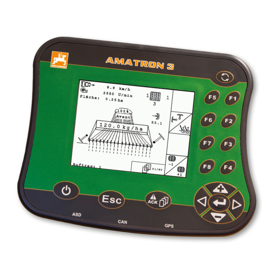
Control terminal
Hide thumbs
Also See for AMATRON 3:
- Operating instructions manual (136 pages) ,
- Operating manual (98 pages)

Subscribe to Our Youtube Channel
Related Manuals for Amazone AMATRON 3


Summary of Contents for Amazone AMATRON 3
- Page 1 Operating instructions MG5560-EN-II | E.1 | 21.04.2020 Control terminal AMATRON 3 This operating manual is valid from software version: 01.09.00 Original operating instructions...
-
Page 3: Table Of Contents
TABLE OF CONTENTS TABLE OF CONTENTS 1 About this operating manual 7 AMATRON 3 configuration Other applicable documents Entering the basic settings 7.1.1 Enabling or disabling job Validity management Diagrams 7.1.2 Enabling or disabling ignition switching 1.3.1 Notes 7.1.3 Adjusting the volume 1.3.2... - Page 4 TABLE OF CONTENTS 7.11.4 Performing a reset 10.3.11 Editing the product data 8 Configuring implements 11 Using the GPS switch Managing implements 11.1 GPS switch overview 11.1.1 GPS switch interface Editing the implement data 11.1.2 GPS switch functions Editing the implement geometry 11.1.3 GPS quality requirements data...
- Page 5 TABLE OF CONTENTS 11.11.3 Deleting the headland 11.12 Using track lines 11.12.1 Selecting the track line pattern 11.12.2 Defining the track line spacing 11.12.3 Creating beds 11.12.4 Defining the light bar sensitivity 11.12.5 Creating track lines 11.13 Using part-width section control 11.13.1 Using manual part-width section control...
-
Page 7: About This Operating Manual
1 | About this operating manual About this operating manual CMS-T-006637-B.1 Other applicable documents CMS-T-00000217-A.1 Operating manual for the GPS receiver Operating manual for the implement software Validity CMS-T-006632-A.1 These operating instructions are valid for software version 01.09.00 For information on the software version: "Setup" > "Diagnosis"... -
Page 8: Instructions
1 | About this operating manual Diagrams 1.3.2 Instructions CMS-T-00000473-B.1 Numbered instructions CMS-T-005217-B.1 Actions that have to be performed in a specific sequence are represented as numbered instructions. The specified sequence of the actions must be observed. Example: 1. Instruction 1 2. -
Page 9: Lists
1 | About this operating manual Diagrams Example: Instruction Instructions without sequence CMS-T-005214-C.1 Instructions that do not require a specific sequence are shown as a list with arrows. Example: Instruction Instruction Instruction 1.3.3 Lists CMS-T-001852-A.1 Lists are used, for example, to show different selection options. -
Page 10: Orientation Paths
1 | About this operating manual Diagrams Item 1 Item 2 Item 3 1.3.5 Orientation paths CMS-T-00000021-A.1 Orientation paths located at the beginning of text sections with instructions for action help with rapid orientation, especially for selective reading relating to problems Example: "Setup"... -
Page 11: Installation Instructions
1. Mount the GPS receiver on the tractor, please refer to the operating manual for the GPS receiver. The AMATRON 3 control terminal can be connected to the tractor basic equipment or with the ISOBUS wiring. The tractor basic equipment (console with... -
Page 12: Mounting For Isobus Mode
2 | Installation instructions Mounting for ISOBUS mode Mounting for ISOBUS mode CMS-T-006370-A.1 CMS-I-001583 For implements that are connected to an ISOBUS tractor using the ISOBUS light cabling: Disable the ISOBUS function of the tractor terminal. MG5560-EN-II | E.1 | 21.04.2020... -
Page 13: Mounting For Amabus Mode
2 | Installation instructions Mounting for AMABUS mode Mounting for AMABUS mode CMS-T-006473-B.1 CMS-I-001582 MG5560-EN-II | E.1 | 21.04.2020... -
Page 14: Mounting For Parallel Operation
2 | Installation instructions Mounting for parallel operation Mounting for parallel operation CMS-T-006476-B.1 CMS-I-002303 MG5560-EN-II | E.1 | 21.04.2020... -
Page 15: Amatron 3 Overview
2 F keys: Press the buttons on the display 5 Escape: Back, cancel 3 Directional pad: Change the selection on the 6 On/Off button: Switching the AMATRON 3 on and display, change numerical values, confirm selections MG5560-EN-II | E.1 | 21.04.2020... -
Page 16: Rear Side
3 | AMATRON 3 overview Rear side Rear side CMS-T-00004670-A.1 Shift key CMS-T-005609-A.1 1 Shift key for the work menu of the implement controls CMS-I-001943 Rating plate and CE mark CMS-T-005605-A.1 The following information is listed on the rating plate: 1 Implement ID no. -
Page 17: Basic Operation
4 | Basic operation Basic operation CMS-T-005654-C.1 Using the toggle button CMS-T-001877-B.1 The toggle button 1 can be used to switch among the selected menus. To switch among the selected menus consecutively, press briefly. To switch to the main menu, press and hold. -
Page 18: Using The F Keys
4 | Basic operation Using the F keys Using the F keys CMS-T-001882-B.1 The arrangement of the keys "F1" to "F8" corresponds to the arrangement of the buttons on the display. When explaining the procedures, this operating manual uses the symbols on the buttons. To execute the procedures, the corresponding F key must be pressed. -
Page 19: Entering Numerical Values
4 | Basic operation Entering numerical values Text menu overview : Move the curser left and right : Deletes the character in front of the curser : Switch between upper and lower case letters : Shows letters with accents : Clears the input field 1. -
Page 20: Using The Shift Key
When the shift key is active, it is shown on the display. Press on the rear side of the AMATRON 3. Other function field will be shown, which changes the assignment of the function keys. MG5560-EN-II | E.1 | 21.04.2020... -
Page 21: After Switching On
5 | After switching on After switching on CMS-T-00004671-A.1 Selecting the BUS mode CMS-T-003915-A.1 After starting the AMATRON 3, it is possible to select between 2 BUS modes. The selection of the BUS mode depends on the connected implement. BUS modes: AMABUS... -
Page 22: Checking The Aux-N Assignments
The set BUS mode is shown in the main menu CMS-I-002124 Checking the AUX-N assignments CMS-T-003920-A.1 Each time the AMATRON 3 is restarted, the assignment of the external input devices must be checked and confirmed for safety reasons. The AMATRON 3 only recognises external input devices in ISOBUS mode. -
Page 23: Changing The Aux-N Assignments
5 | After switching on Changing the AUX-N assignments A list of all available functions is opened. The list contains the functions of the AMATRON 3 and the functions of the devices connected. 1. Scroll through the assignment list with... -
Page 24: Main Menu Overview
6 | Main menu overview Main menu overview CMS-T-003525-A.1 Time and date Selected implement Selected tractor Started job Activated GPS applications with remaining time in hours : Opens the GPS switch. Using the GPS switch, see page 74 : Opens the implement controls. The symbol varies depending on the connected implement. -
Page 25: Amatron 3 Configuration
1. Select "Setup" > "Settings" > "Basic settings". 2. Enable or disable job management 3. Restart the AMATRON 3. CMS-I-001209 7.1.2 Enabling or disabling ignition switching CMS-T-004834-A.1 This setting defines whether the AMATRON 3 is coupled with the vehicle ignition. MG5560-EN-II | E.1 | 21.04.2020... -
Page 26: Adjusting The Volume
1. Select "Setup" > "Settings" > "Basic settings". Possible settings: : When the vehicle ignition is switched on or off, the AMATRON 3 is switched on or off. : The AMATRON 3 must be switched on and off manually. CMS-I-002050 2. Enable or disable ignition switching 7.1.3 Adjusting the volume... -
Page 27: Setting The Brightness
7 | AMATRON 3 configuration Entering the basic settings 7.1.4 Setting the brightness CMS-T-001958-A.1 Select "Setup" > "Settings" > "Basic settings" > "Brightness". CMS-I-001695 Possible settings: : Percent value for the display brightness during the day : Percent value for the display brightness at night : Sets the display brightness to the value entered under "Brightness for operation at night". -
Page 28: Setting The Date And Time
7 | AMATRON 3 configuration Entering the basic settings 7.1.5 Setting the date and time CMS-T-001969-A.1 Select "Setup" > "Settings" > "Basic settings" > "Date and time". CMS-I-001700 Possible settings: : Day, month and year for the current date : Hours and minutes for the current time... -
Page 29: Setting The Region And Language
7 | AMATRON 3 configuration Entering the basic settings 7.1.6 Setting the region and language CMS-T-001974-A.1 Select "Setup" > "Settings" > "Basic settings" > "Region and language". CMS-I-002381 Possible settings: : Language for the user interface : Point or comma as a separator for decimal numbers (0.1 or 0,1) -
Page 30: Configuring Isobus
AMATRON 3, the Task Controller ID must match with the Task Controller ID of the implement. If the AMATRON 3 is the only connected terminal, the implement automatically adopts the Task Controller ID of the AMATRON 3. -
Page 31: Gps Configuration
7 | AMATRON 3 configuration GPS configuration If an implement is connected to the ASD interface, the TC-ID ASD/GPS maps defines where the incoming data should be sent. To be able to use the ASD interface and GPS maps, the TC-ID ASD/GPS maps must match with the Task Controller ID 5. - Page 32 7 | AMATRON 3 configuration GPS configuration NOTE With the SBAS correction signal, a signal with higher accuracy is available as long as the SBAS correction signal is received. SBAS includes the correction services EGNOS, WAAS and MSAS. For more information on this topic, please consult the operating manual for the satellite receiver.
-
Page 33: Setting Up The Smart6 Receiver
7 | AMATRON 3 configuration GPS configuration 1. Select "GPS driver" > "AG-STAR/SMART6". 2. Under "Correction signal", select the desired correction signal. 7.3.3 Setting up the SMART6 receiver CMS-T-00000274-A.1 The SMART6 can receive the TerraStar correction signal and therefore offers higher accuracy. -
Page 34: Setting Up Other Gps Receivers
7 | AMATRON 3 configuration Setting up the ASD interface 7.3.4 Setting up other GPS receivers CMS-T-005821-B.1 1. Select "GPS driver" > "Other". 2. Under "Baud rate", enter the baud rate for the GPS receiver. NOTE More information on the baud rate can be found in the GPS receiver operating manual. -
Page 35: Adjusting The Light Bar
7 | AMATRON 3 configuration Adjusting the light bar Adjusting the light bar CMS-T-004993-A.1 The light bar 1 shows the deviation of the tractor from the guide track and thereby enables precise following of the guide tracks. 1. Select "Setup" > "Settings" > "Interfaces" > "Light bar". -
Page 36: Defining The Start Mode
2. Select the menus that should be reached using the toggle button. Defining the start mode CMS-T-001948-A.1 The AMATRON 3 can be started in 3 different modes. Select "Setup" > "Settings" > "Start mode". Possible settings: : The BUS mode can be selected when the AMATRON 3 is started. -
Page 37: Using Aux-N Input Devices
AMATRON 3 for the GPS functions. Select "Setup" > "Settings" > "Parallel operation". Possible settings: : The AMATRON 3 can be used to access the implement controls and the GPS functions are available. : The AMATRON 3 can only be used to access the implement controls. - Page 38 7 | AMATRON 3 configuration Using AUX-N input devices Possible settings: Define the AUX-N assignment using the functions list, see page 32 Define the AUX-N assignment using the input list, see page 33 7.9.1.1 Defining the AUX-N assignment using the functions list CMS-T-002245-A.1...
- Page 39 7 | AMATRON 3 configuration Using AUX-N input devices 7.9.1.2 Defining the AUX-N assignment using the input list CMS-T-002235-A.1 For the AUX-N assignment using the input list, all of the available buttons are listed on the left side. These buttons can be assigned to functions.
-
Page 40: Defining The Aux-N Assignment Using The Functions List
7 | AMATRON 3 configuration Using AUX-N input devices 3. Confirm with "Yes". The assignment will be deleted. 7.9.1.4 Deleting all AUX-N assignments CMS-T-002240-A.1 1. Select 2. Confirm with "Yes". The assignment will be deleted. 7.9.2 Defining the AUX-N assignment using the functions list CMS-T-002245-A.1... -
Page 41: Defining The Aux-N Assignment Using The Input List
7 | AMATRON 3 configuration Using AUX-N input devices If the functions are not listed on the left side: select 2. Select a function from the list. The list of available buttons will be opened. CMS-I-001178 3. Select a button from the list. -
Page 42: Deleting The Selected Aux-N Assignment
7 | AMATRON 3 configuration Using AUX-N input devices 3. Select a function from the list. The button is assigned to the selected function. CMS-I-001180 7.9.4 Deleting the selected AUX-N assignment CMS-T-005136-A.1 1. Select the desired assignment from the list. -
Page 43: Deleting All Aux-N Assignments
50 hours. To be able to use the applications without restrictions, the license key must be purchased from AMAZONE. Licence management can be used to activate the 3 applications on the AMATRON 3, to be able to use these applications permanently. MG5560-EN-II | E.1 | 21.04.2020... - Page 44 7 | AMATRON 3 configuration Using the licence management The following table shows an overview of the functions that are activated with the licences. Functions GPS switch GPS track GPS maps No licence Setting reference points and calibrating the GPS...
-
Page 45: Using The Diagnostics
7 | AMATRON 3 configuration Using the diagnostics 3. Press 4. Enter the license key and confirm. The application is activated. NOTE If the licence keys were accidentally deleted, press to restore them. 7.11 Using the diagnostics CMS-T-00004674-A.1 7.11.1 Using USB management CMS-T-00004700-A.1... -
Page 46: Using The Pool Management
7 | AMATRON 3 configuration Using the diagnostics REQUIREMENTS Job management enabled; see page 19 select The job data will be saved to the USB flash drive. 7.11.2 Using the pool management CMS-T-001990-A.1 "Pool" refers to a file that describes the representation of the implement software on the terminal. -
Page 47: Performing A Reset
AMATRON 3 setting can be reset. 1. Select "Setup" > "Setting" > "Diagnosis" > "Reset". To reset the GPS switch settings, Select "Reset GPS switch/track". To reset the AMATRON 3 settings and delete the data, Select "Factory settings". 4. Confirm the reset. CMS-I-002209... -
Page 48: Configuring Implements
To be able to use the GPS switch functions, the following implements must be configured: AMABUS implements Implements that cannot communicate with the terminal Using the entered implement data, the AMATRON 3 can control the connected implement. The following implement data must be entered: Implement name Implement type... -
Page 49: Editing The Implement Data
8 | Configuring implements Editing the implement data Select Main menu > "Implements". CMS-I-002180 Implement menu overview Existing implements Information on the selected implement : Opens the main menu : Adds an implement : Deletes the selected implement CMS-I-002213 : Opens the implement data for the selected implement, see page 43 Editing the implement data CMS-T-002023-B.1... -
Page 50: Editing The Implement Geometry Data
"Implement type". NOTE The implement type can only be selected if the AMATRON 3 was started in AMABUS mode, see page 15. 5. Under "Number of part-width sections", enter the CMS-I-002221 number of part-width sections for the implement. -
Page 51: Selecting The Implement
8 | Configuring implements Selecting the implement section control, track guidance and variable rate control depend on the correct geometry. 1. Select "Implement data" > "Geometry data". CMS-I-002225 2. Under "X1", enter the distance between the coupling point and the application point. NOTE Application points: Field sprayers: Spray nozzles... - Page 52 8 | Configuring implements Selecting the implement AMABUS implement Implements that cannot communicate with the terminal ISOBUS implements sign in to the BUS automatically and do not require configuration. REQUIREMENTS Edit implement data, see page 43 Selectable implements have a check box: Mark the desired implement.
-
Page 53: Configuring Tractors
9 | Configuring tractors Configuring tractors CMS-T-00004676-A.1 Managing tractors CMS-T-001903-B.1 For the AMATRON 3 to be able to control the connected implement properly, the data for the utilised tractor must be transmitted to the AMATRON The following tractor data is required: Geometry data... -
Page 54: Editing The Tractor Data
9 | Configuring tractors Editing the tractor data Select Main menu> "Tractors". CMS-I-002171 Tractor menu overview Available tractors Information on the selected tractor : Opens the main menu : Adds a tractor, see page 48 : Deletes the selected tractor CMS-I-001576 : Opens the tractor data for the selected tractor for editing.see page 48... -
Page 55: Editing The Tractor Geometry Data
9 | Configuring tractors Editing the tractor geometry data 2. Enter a name for the tractor under "Name". CMS-I-001277 Editing the tractor geometry data CMS-T-002589-B.1 The implement geometry data is required for the GPS switch to function properly. The part-width section control, track guidance and variable rate control depend on the correct geometry. - Page 56 9 | Configuring tractors Editing the tractor geometry data If the receiver is installed to the right of the centre of the axle, enter a positive value for the distance between the GPS receiver and the centre of the axle under "A"...
-
Page 57: Configuring The Tractor Sensors
The tractor sensor must only be configured if the tractor does not have any speed sensors and therefore does not send speed data. In the case, the speed data can be transmitted to the AMATRON 3 by external sensors, e.g. wheel sensors or GPS sensors. REQUIREMENTS... -
Page 58: Selecting The Tractor
9 | Configuring tractors Selecting the tractor Selecting the tractor CMS-T-004819-A.1 To use the GPS switch, a tractor must be selected. REQUIREMENTS Tractor data edited, see page 43 Mark the desired tractor. The tractor is selected. CMS-I-001273 MG5560-EN-II | E.1 | 21.04.2020... -
Page 59: Using The Job Management
GPS switch map. The stored setpoints are transmitted to the implement and processed. When a job has been started on the AMATRON 3, the field boundaries and the application map are displayed on the GPS switch map and the job data is recorded. - Page 60 10 | Using the job management Managing jobs REQUIREMENTS Job management is enabled, see page 19 USB flash drive is inserted Main menu > "Jobs". CMS-I-002175 Job menu overview Existing jobs Information on the selected job : Opens the main menu : Opens the master data menu, see page : Adds a job, see page 55 CMS-I-002241...
-
Page 61: Editing Jobs
Editing jobs CMS-T-00004679-B.1 10.2.1 Creating a new job CMS-T-002036-B.1 With the AMATRON 3, jobs can be created in ISO- XML format and edited. The created jobs can be exported and further processed with a Farm Management Information System (FMIS). The following additional data can be added to the... - Page 62 10 | Using the job management Editing jobs The setpoints for the application/spread rates can come from the following sources: Setpoints created on the AMATRON 3 From an imported application map in shape format From an external device using the ASD interface REQUIREMENTS...
- Page 63 10 | Using the job management Editing jobs 2. Select "Setpoints". The "Setpoints" menu will be opened. The controllable implement elements will be shown. CMS-I-002565 MG5560-EN-II | E.1 | 21.04.2020...
-
Page 64: Adding A Worker To A Job
The menu for selecting the setpoint will be opened. The setpoints created in the master data will be shown. NOTE If no setpoints are available, the AMATRON 3 automatically opens the menu for creating a setpoint. In this case, see page 68. CMS-I-001739 4. - Page 65 10 | Using the job management Editing jobs REQUIREMENTS Worker is created in the master data, see page 67 Job is started, see page 64 1. Select "Jobs" > Started job. CMS-I-002248 2. select CMS-I-001494 The "Assign worker" menu will be opened. The already assigned workers will be shown.
-
Page 66: Adding Implements And Tractors To A Job
10 | Using the job management Editing jobs To add a worker: select 4. Select the desired worker from the list. The selected worker will be added to the job. CMS-I-001747 To start the working time recording for a worker: select To stop the working time recording for a worker:... - Page 67 10 | Using the job management Editing jobs REQUIREMENTS Implement is configured, see page 42 Tractor is configured, see page 47 Job is started, see page 64 1. Select "Jobs" > Started job. CMS-I-002082 2. select CMS-I-002324 The "Implement assignment" menu will be opened.
-
Page 68: Checking The Map Type
CMS-T-006643-B.1 If a job with an application map in ISO-XML format was imported from the Farm Management Information System to the AMATRON 3, the map type is shown here. Map type 1: The application map is displayed in GPS switch and the setpoints are processed. -
Page 69: Searching For Jobs
10 | Using the job management Editing jobs 10.2.6 Searching for jobs CMS-T-002043-A.1 1. Select Jobs > 2. Enter the search term. 3. Confirm the entry. The found jobs are displayed. CMS-I-001979 10.2.7 Copying jobs CMS-T-002051-A.1 To process jobs with the same data several times, the jobs can be copied. -
Page 70: Starting A Job
10 | Using the job management Editing jobs 1. "Jobs" > Select a job. 2. select 3. Confirm the copying. CMS-I-002248 The job will be copied and marked with a "*". CMS-I-001983 10.2.8 Starting a job CMS-T-001583-A.1 When a job is started, the job data is recorded. The field data stored in the job are shown on the map in GPS switch. -
Page 71: Stopping A Job
10 | Using the job management Editing jobs REQUIREMENTS Job is imported or created: Importing jobs, see page Creating jobs, see page 55 1. "Jobs" > Select a job. 2. select The selected job will be started. CMS-I-001979 10.2.9 Stopping a job CMS-T-001589-A.1 When a job is stopped, the job data is no longer recorded. -
Page 72: Using Master Data Management
10.3.1 Managing master data CMS-T-00004699-A.1 Master data is additional information that can be created and saved on the AMATRON 3. The created master data can be added to jobs. Master data from a Farm Management Information System (FMIS) cannot be edited. -
Page 73: Managing Setpoints
10 | Using the job management Using master data management Select "Jobs" > CMS-I-002248 The "Master data" menu will be opened. Possible settings: : Manage the "Setpoints", see page 67 : Manage the "Fields", see page 69 : Manage the "Customers", see page 70 : Manage the "Workers", see page 71 : Manage the "Products", see page 72 CMS-I-001240... -
Page 74: Editing The Setpoints
10 | Using the job management Using master data management Select "Jobs" > > "Setpoints". Setpoint menu overview : Opens the master data menu : Adds a setpoint : Deletes the selected setpoint CMS-I-001461 10.3.3 Editing the setpoints CMS-T-003930-A.1 Setpoints can consist of several products to document which product was used for the job. -
Page 75: Managing Fields
10 | Using the job management Using master data management : Line for the total application/spread rate : Line for one product. CMS-I-001465 2. Enter the setpoints for the product in the first column. 3. In the second column, enter the units for the setpoints. -
Page 76: Editing The Field Data
10 | Using the job management Using master data management Select "Jobs" > > "Fields". : Opens the master data menu : Adds a field : Deletes the selected field : Opens the search function; see page 63 CMS-I-002257 10.3.5 Editing the field data CMS-T-002252-A.1 1. -
Page 77: Editing The Customer Data
10 | Using the job management Using master data management Select "Jobs" > > "Customers". Customer menu overview Existing customers Information on the selected customer : Opens the master data menu : Adds a customer : Deletes the selected customer CMS-I-002024 : Opens the search function 10.3.7 Editing the customer data... -
Page 78: Editing Worker Data
10 | Using the job management Using master data management Select "Jobs" > > "Worker". Worker menu overview : Opens the master data menu : Adds a worker : Deletes the selected worker : Opens the search function CMS-I-001500 10.3.9 Editing worker data CMS-T-003415-A.1 1. -
Page 79: Editing The Product Data
10 | Using the job management Using master data management Select "Jobs" > > "Products". Product menu overview : Opens the master data menu : Adds a product : Deletes the selected product : Opens the search function CMS-I-001305 10.3.11 Editing the product data CMS-T-003475-A.1 1. -
Page 80: Using The Gps Switch
11 | Using the GPS switch Using the GPS switch CMS-T-006135-D.1 11.1 GPS switch overview CMS-T-00004684-B.1 11.1.1 GPS switch interface CMS-T-00004685-B.1 11.1.1.1 Symbols on the map CMS-T-005238-A.1 CMS-I-002037 MG5560-EN-II | E.1 | 21.04.2020... - Page 81 11 | Using the GPS switch GPS switch overview Field boundary warning "GPS" speed Compass Worked area and remaining area Worked area in light green, double-worked areas Obstacle in dark green 10 "Virtual" headlands in grey Tractor symbol and implement symbol 11 Track line with track line number Field boundary in red 12 Mode for the part-width section control...
- Page 82 11 | Using the GPS switch GPS switch overview 11.1.1.3 GPS switch menu CMS-T-005248-B.1 Page 1 : Opens the main menu : Changes between Page 1 and Page 2 starts and stops the recording for a manual implement starts and stops the recording for an ISOBUS or AMABUS implement : Opens the "Field data"...
-
Page 83: Gps Switch Functions
When the part-width sections of the connected implement are switched on, the worked area is marked in green on the map of the AMATRON 3. To achieve optimal coverage, the AMATRON 3 can automatically switch the part-width sections of the connected implement on and off. - Page 84 11.1.2.2 Track guidance with GPS track CMS-T-004867-A.1 Track lines can be created on the AMATRON 3 to support the driver in working the field seamlessly. After the track lines have been created, they are shown on the map.
-
Page 85: Gps Quality Requirements
11 | Using the GPS switch Entering the basic settings for GPS switch 11.1.3 GPS quality requirements CMS-T-006650-A.1 GPS quality 0 to 6 (nominal state) Good DGPS HDOP 6 to 8 Medium HDOP greater than 8 Poor HDOP 0 to 6 Medium HDOP 6 to 8 Poor... -
Page 86: Select The Source For The Driving Direction Detection
"Turn around direction" function is not available. 11.2.3 Enabling the acoustic field boundary warning CMS-T-003430-A.1 When the vehicle approaches the field boundary, the AMATRON 3 can issue a warning tone. Select "GPS switch" > > "Acoustic field boundary warning". CMS-I-001655... -
Page 87: Defining The Map Display
11 | Using the GPS switch Entering the basic settings for GPS switch 11.2.4 Defining the map display CMS-T-003405-A.1 The map in GPS switch can be displayed in two or three dimensions. 1. Select "GPS switch" > > "Map display". 2. -
Page 88: Entering The Gps Switch Settings For Spreaders
This function defines whether a safety zone is automatically created inside a field boundary. REQUIREMENTS For AMABUS spreaders: Spreader is connected The AMATRON 3 is started in AMABUS mode, see page 15 Spreader is selected in the implement menu, see page 45 For ISOBUS spreaders:... - Page 89 1 from reaching into the headlands. CMS-I-002104 REQUIREMENTS For AMABUS spreaders: Spreader is connected The AMATRON 3 is started in AMABUS mode, see page 15 Spreader is selected in the implement menu, see page 45 The geometry values for the spreader were...
-
Page 90: Entering The Gps Switch Settings For Sprayers
11 | Using the GPS switch Entering the basic settings for GPS switch 11.2.7 Entering the GPS switch settings for sprayers CMS-T-00004682-A.1 11.2.7.1 Setting the automatic boom lowering CMS-T-006124-A.1 The automatic boom lowering automatically lowers the boom when the sprayer moves onto an unworked area. -
Page 91: Entering The Gps Switch Settings For Seed Drills
Entering the basic settings for GPS switch REQUIREMENTS For AMABUS sprayers: The sprayer is connected The AMATRON 3 is started in AMABUS mode, see page 15 Sprayer is selected in the implement menu, see page 45 Field boundary has been created, see... - Page 92 124. REQUIREMENTS For AMABUS seed drills: Seed drill is connected The AMATRON 3 is started in AMABUS mode, see page 15 Seed drill is selected in the implement menu, see page 45 For ISOBUS seed drills:...
-
Page 93: Setting The On/Off Point Delays
11 | Using the GPS switch Entering the basic settings for GPS switch 11.2.9 Setting the on/off point delays CMS-T-005059-A.1 When the part-width sections are switched on 1 , it takes a few hundred milliseconds until the application/ spreading actually starts 2 . The switch-on delay 3 can cause underlaps in working the field. - Page 94 11 | Using the GPS switch Entering the basic settings for GPS switch On/off point delay for switching off On/off point delay for switching on CMS-I-001618 CMS-I-001810 (A) Length of the overlap Switching off: Entering a worked area Switching on: Moving off a worked area Sprayer: Reduce the on/off point delay Sprayer: Reduce the on/off point delay Seed drill: Increase the on/off point delay...
- Page 95 11 | Using the GPS switch Entering the basic settings for GPS switch REQUIREMENTS AMABUS implement is connected The AMATRON 3 is started in AMABUS mode, see page 15 AMABUS implement is selected in the implement menu, see page 45 1.
-
Page 96: Determining The Correction Times For On/Off Point Delays
11 | Using the GPS switch Entering the basic settings for GPS switch 11.2.10 Determining the correction times for on/off point delays CMS-T-006363-C.1 Length of the overlap (A) / Length of the unworked area (B) 0.5 m 1.0 m 1.5 m 2.0 m 2.5 m 3.0 m... -
Page 97: Checking The Switch-On And -Off Times
REQUIREMENTS ISOBUS implement is connected The AMATRON 3 is started in ISOBUS mode, see page 15 1. In the GPS switch settings, check the values for the "Switch-on time" and for the "Switch-off time". -
Page 98: Starting The Gps Switch
11 | Using the GPS switch Starting the GPS switch 11.3 Starting the GPS switch CMS-T-00004702-A.1 11.3.1 Starting GPS switch with job management CMS-T-005147-A.1 When job management is enabled, jobs in ISO-XML format can be imported and processed. REQUIREMENTS If GPS switch should be started with job management, the following requirements must be met: GPS is configured;... - Page 99 11 | Using the GPS switch Starting the GPS switch TROUBLESHOOTING Are the contents not being displayed on the GPS switch map? The requirements for starting GPS switch have not been met. Error symbols are flashing on the GPS switch map. CMS-I-001543 1.
-
Page 100: Starting Gps Switch Without Job Management
11 | Using the GPS switch Starting the GPS switch 11.3.2 Starting GPS switch without job management CMS-T-005152-A.1 REQUIREMENTS If GPS switch should be started without job management, the following requirements must be met: GPS is configured; see page For ISOBUS implements and AMABUS implements: Implement is connected For ISOBUS implements: ISOBUS is configured, see page 24... -
Page 101: Zooming The Map
11 | Using the GPS switch Zooming the map TROUBLESHOOTING Are the contents not being displayed on the GPS switch map? The requirements for starting GPS switch have not been met. Error symbols are flashing on the GPS switch map. CMS-I-001543 1. -
Page 102: Panning The Map
11 | Using the GPS switch Panning the map To zoom the map in larger increments, press To zoom the map back to the standard dimensions and to focus on the vehicle symbol, Press 11.5 Panning the map CMS-T-001615-A.1 The map is zoomed and panned with the directional pad. -
Page 103: Marking Obstacles
11 | Using the GPS switch Marking obstacles When the tractor is driving in reverse, but the tractor symbol is oriented to the front: Select If the tractor is driving forwards, but the tractor symbol is oriented to the rear: Select 11.7 Marking obstacles... -
Page 104: Deleting An Obstacle Marking
CMS-T-001595-B.1 The AMATRON 3 can create a field boundary from the worked area. Using the field boundary, the AMATRON 3 can calculate the size of the field. The worked area and the remaining area result from the field size. MG5560-EN-II | E.1 | 21.04.2020... -
Page 105: Deleting The Field Boundary
11 | Using the GPS switch Deleting the field boundary REQUIREMENTS Completely work the field edge "GPS switch" > The field boundary is laid around the worked area. 11.10 Deleting the field boundary CMS-T-004872-A.1 1. "GPS switch" > 2. Confirm deleting. MG5560-EN-II | E.1 | 21.04.2020... -
Page 106: Managing Virtual Headlands
11 | Using the GPS switch Managing virtual headlands 11.11 Managing virtual headlands CMS-T-00004687-A.1 11.11.1 Creating virtual headlands CMS-T-003520-B.1 REQUIREMENTS Field boundary has been created, see page 98 1. "GPS switch" > 2. Enter and confirm the headland width. A query regarding the headland track line will be shown. - Page 107 11 | Using the GPS switch Managing virtual headlands NOTE When the first headland track line is not laid on the field boundary, the first headland track line lies half of the working width away from the field boundary inside the field. If the first headland track line should be laid on the field boundary, Select "Yes"...
-
Page 108: Locking Or Unlocking The Headlands
11 | Using the GPS switch Managing virtual headlands 11.11.1.2 Deleting the headland CMS-T-003540-A.1 1. "GPS switch" > 2. Confirm deleting. The headland has been deleted. 11.11.2 Locking or unlocking the headlands CMS-T-003550-B.1 The headlands can be locked or unlocked for application/spreading. -
Page 109: Using Track Lines
To allow the driver to follow the track lines more easily, the light bar is shown above the map on the AMATRON 3. The light bar shows the length of the track deviation. The light bar can be configured in the GPS switch settings. - Page 110 11 | Using the GPS switch Using track lines Available track line Explanation Figure patterns Straight track line that is laid between two points. CMS-I-001478 Straight track line that is laid at a given angle. The specified angle of the track line is relative to the north-south axis.
-
Page 111: Defining The Track Line Spacing
11 | Using the GPS switch Using track lines REQUIREMENTS GPS track is activated, see page 37 1. Select "GPS switch" > > "Track line pattern". 2. Select the desired track line pattern and confirm. CMS-I-001987 11.12.2 Defining the track line spacing CMS-T-003465-A.1 The track line spacing is automatically defined as one working width. -
Page 112: Defining The Light Bar Sensitivity
11 | Using the GPS switch Using track lines worked area must be travelled to create a bed of the desired size. The entered number indicates the rhythm in which the track lines must be followed. If e.g. a 2 is entered, every second track line must be followed. -
Page 113: Creating Track Lines
11 | Using the GPS switch Using track lines 1. Select "GPS switch" > > "Light bar sensitivity". 2. Enter the length of the required track line deviation and confirm. CMS-I-002086 11.12.5 Creating track lines CMS-T-00004689-A.1 11.12.5.1 Creating an A-B line CMS-T-005582-A.1 REQUIREMENTS "A-B"... - Page 114 11 | Using the GPS switch Using track lines 3. Drive to the end of the row. 4. select The end point of the track line is set on the vehicle position. Other track line are added. CMS-I-002054 11.12.5.2 Creating contour lines CMS-T-005572-A.1 REQUIREMENTS "Contour"...
-
Page 115: Using Part-Width Section Control
11 | Using the GPS switch Using part-width section control 11.12.5.3 Creating A+ lines CMS-T-005577-A.1 REQUIREMENTS "A+" track line pattern is selected; see page 103 1. Drive to the beginning of the row. 2. select The number area for entering the track line angle will be opened. - Page 116 11 | Using the GPS switch Using part-width section control REQUIREMENTS For AMABUS implements and manual implements: The AMABUS implement or manual implement is configured, see page 42 For ISOBUS implements: The ISOBUS implement is connected AMABUS and ISOBUS implements CMS-T-005666-A.1 The recording of the worked areas starts when the part-width sections are manually switched on, and...
-
Page 117: Using Automatic Part-Width Section Control
11 | Using the GPS switch Using part-width section control 11.13.2 Using automatic part-width section control CMS-T-00004693-A.1 11.13.2.1 Activating automatic part-width section control CMS-T-006234-B.1 GPS switch can be operated in manual mode and in automatic mode. In automatic mode, the automatic part-width section control is enabled. - Page 118 11 | Using the GPS switch Using part-width section control 11.13.2.2 Defining the degree of overlap CMS-T-003425-A.1 The degree of overlap defines the percent by which a part-width section can protrude over a boundary before it is switched off. The set degree of overlap 1 is shown beside the symbol for automatic mode.
- Page 119 11 | Using the GPS switch Using part-width section control Possible settings: Explanation Figure The part-width sections are switched off before any overlap occurs. CMS-I-002003 The part-width sections are switched off when 50 % they half protrude over a boundary. CMS-I-002002 The part-width sections are switched when they...
- Page 120 11 | Using the GPS switch Using part-width section control 1. Select "GPS switch" > "Degree of overlap". 2. Select the percent value and confirm. CMS-I-002265 11.13.2.3 Defining the overlap tolerance CMS-T-003410-A.1 The overlap tolerance defines how far the outer part- width sections can protrude over a worked area before they are switched off.
- Page 121 11 | Using the GPS switch Using part-width section control 11.13.2.4 Defining the overlap tolerance at the field boundary CMS-T-003440-A.1 The overlap tolerance at the field boundary defines how far the outer part-width sections can protrude over the field boundary before they are switched off. Overlap tolerance at the field boundary prevents the outer part-width sections from being constantly switched on and off when driving along and touching...
- Page 122 11 | Using the GPS switch Using part-width section control 11.13.2.5 Defining the overlap in the direction of travel CMS-T-003435-A.1 The overlap in the direction of travel indicates how far the part-width sections can protrude over a boundary in the direction of travel before they are switched off. Overlap in the direction of travel prevents gaps from occurring between the headlands and the rows or between the worked areas.
-
Page 123: Managing Field Data
Managing field data CMS-T-00004694-A.1 11.14.1 Saving recorded field data CMS-T-003499-A.1 Field data that was created with the AMATRON 3 can be saved as a recording to a USB flash drive. Saved recordings can be loaded at a later time and used again. -
Page 124: Loading Field Data From Recordings
The field data will be deleted. 11.14.3 Loading field data from recordings CMS-T-003515-B.1 Recordings are field data files that were created with an AMATRON 3 and saved. The following field data can be loaded: Field boundaries Worked area Track lines... - Page 125 11 | Using the GPS switch Managing field data REQUIREMENTS Recordings are available on the USB flash drive 1. Select "GPS switch" > The field data menu will be opened. 2. In the field data menu, select 3. Select "Recording". The saved field data files will be displayed.
- Page 126 11 | Using the GPS switch Managing field data To delete a field data file: Select To search for field data files: Select To show all field data file for fields within a radius: Select NOTE The radius for which the existing field data files are shown depends on the corresponding GPS switch setting, see page 120.
-
Page 127: Defining The Radius For Field Detection
11 | Using the GPS switch Managing field data 1. Select "GPS switch" > > "Detect fields (radius)". 2. Enter the radius for field detection and confirm. 11.14.4 Defining the radius for field detection CMS-T-003445-A.1 The field detection radius defines which field data files are shown when field data is imported. -
Page 128: Loading Field Data From A Shape File
11 | Using the GPS switch Managing field data 11.14.5 Loading field data from a shape file CMS-T-003504-B.1 1. GPS switch > The field data menu will be opened. 2. In the field data menu, select 3. Select "GIS import". 4. - Page 129 11 | Using the GPS switch Managing field data 5. Select the shape file and confirm. The selected field data type will be imported. NOTE Imported application maps must be configured, see page 123. 11.14.5.1 Configuring the application map CMS-T-005142-A.1 If "Application maps"...
-
Page 130: Configuring The Application Map
11 | Using the GPS switch Using the driver assistance system 11.14.6 Configuring the application map CMS-T-005142-A.1 If "Application maps" was selected when importing the field data, further settings must be entered. 1. Select the values for the application/spread rate. 2. - Page 131 At the configured distance from the headland, an additional symbol for the switch point of the implement will be shown. The AMATRON 3 issues two short, low tones. 2. Maintain constant speed. When the additional symbol has reached the headland boundary, the part-width sections are switched off.
-
Page 132: Calibrating The Gps Switch
11 | Using the GPS switch Calibrating the GPS switch If the speed becomes irregular before the application/spreading stops, the additional symbol turns red and moves. The AMATRON 3 issues a long, high signal tone. There is overlap or underlap. 11.16 Calibrating the GPS switch CMS-T-00004696-B.1... -
Page 133: Correcting The Gps Drift With A Reference Point
This point can be driven to at any time to compare the real vehicle position with the position of the virtual reference point on the AMATRON 3. In doing so, it is important to always drive to the reference point in the same way and from the same direction. -
Page 134: Correcting The Gps Drift Manually
11 | Using the GPS switch Calibrating the GPS switch 11.16.2.2 Starting the calibration CMS-T-003535-A.1 REQUIREMENTS Reference point is set 1. Drive with the vehicle to the real reference point. 2. Mark the reference point in the list. 3. select The calibration is started. -
Page 135: Using An External Light Bar
11 | Using the GPS switch Using an external light bar 2. Start the manual calibration with The GPS switch map will be shown. CMS-I-001552 3. Move the vehicle symbol using the directional pad. The vehicle symbol will be shifted by the set increment. - Page 136 CMS-I-001806 The light bar must have the same baud rate as the AMATRON 3 and the GPS receiver. The light bar is set to a baud rate of 19200 per default. The baud rate can be changed in the light bar configuration menu.
-
Page 137: Using The Aux-N Menu
12 | Using the AUX-N menu Using the AUX-N menu CMS-T-003875-A.1 If an external input device is connected, the AUX-N menu can be used to access this input device. The functions within the menu depend on the connected external device. In this operating manual, the AUX-N menu is described based on the AmaPilot 1. -
Page 138: Eliminating Faults
See the list of signal requirements. Wait for a few seconds and switch on again. AMATRON 3 is switched on and AMATRON 3 cannot be switched on Pull the 9-pin connector out of off too rapidly the basic equipment and plug it in again. - Page 139 The AMATRON 3 is not UT no. 1 Make the assignment on another Assignments must always be done and is not responsible for the device or allocate the AMATRON 3 on the terminal with UT no.
- Page 140 13 | Eliminating faults Message Cause Remedy The allocation for this function is Manual assignments to this function pre-defined by the device and it are not permitted. cannot be changed. Delete the pool for the corresponding device, see page 40. Error when loading the pool.
-
Page 141: Take Screenshot
14 | Take screenshot Take screenshot CMS-T-00000566-B.1 With a screenshot, an image is made of the displayed software interface and saved as an image file to the USB flash drive. REQUIREMENTS USB flash drive is inserted Press and hold MG5560-EN-II | E.1 | 21.04.2020... -
Page 142: Indexes
(Automated Field-related Documentation). With the DGPS ASD interface, ASD-compatible data can be imported Differential GPS: Differential global position on the AMATRON 3. This includes e.g. data from determination system. A correction system increases sensors. the precision to +/-0.5 m (0.02 m with RTK). - Page 143 Paid system for the correction of satellite data. Field boundary Virtual line on the map of the AMATRON 3. The field boundary marks an area that can be worked. When a field boundary has been created, the AMATRON 3...
-
Page 144: Index
GPS maps enabling Customers GPS switch managing calibration enabling resetting Troubleshooting Dead time setting with job management for seed drills without job management Delay time setting GPS track for seed drills enabling Deleting data AMATRON 3 MG5560-EN-II | E.1 | 21.04.2020... - Page 145 15 | Indexes INDEX Headland distance Licence key entering Headlands restoring creating deleting 102, 102, 117 Licence management loading from a shape file using loading from recording Licences locking 101, 102 saving Light bar unlocking 101, 102 adjustment Implement controls, opening Main menu Implement controls restarting...
- Page 146 Reference point creation entering the coupling data entering the geometry data Reset Sensors configuration AMATRON 3 GPS switch Tractor symbol rotation Safety zone Universal Terminal troubleshooting Select implement type USB flash drive Self-propelled machine configuration...
- Page 148 AMAZONEN-WERKE H. DREYER GmbH und Co. KG Postfach 51 49202 Hasbergen-Gaste Germany +49 (0) 5405 501-0 amazone@amazone.de www.amazone.de...
Need help?
Do you have a question about the AMATRON 3 and is the answer not in the manual?
Questions and answers