
Related Manuals for Amazone AmaTron 4


Summary of Contents for Amazone AmaTron 4
- Page 1 Operating instructions MG6010-EN-GB | G.1 | 13.12.2018 Control terminal AmaTron 4 This operating manual is valid from software version: NW216-B Original operating instructions...
-
Page 3: Table Of Contents
3.2 Work menu Universal Terminal K Configuring implements E Basic operation Configuring ISOBUS implements Switching the AmaTron 4 on and off Configuring non-ISOBUS implements Switching between the applications 2.1 Creating non-ISOBUS implements 2.1 Using the menu buttons 2.2 Configuring non-ISOBUS implements 2.2 Using the application carousel... - Page 4 | TABLE OF CONTENTS | Changing the tractor geometry data Exporting ISO-XML job data Configuring the tractor sensors Q Using part-width section control 3.1 Configuring wheel sensors 3.2 Configuring radar sensors Overlap, setting 3.3 Activating GPS NMEA2000 1.1 Defining the overlap in the direction of 3.4 Configuring the PTO shaft sensor travel 3.5 Configuring the working position...
- Page 5 | TABLE OF CONTENTS | X Using the Universal Terminal Y Taking screenshots Z Using the camera Indexes INDEX MG6010-EN-GB | G.1 | 13.12.2018...
-
Page 6: A About This Operating Manual
A | About this operating manual | About this operating manual CMS-T-00000081-A.1 Meaning of the operating manual CMS-T-006245-A.1 The operating manual is an important document and a part of the implement. It is intended for the user and contains safety-related information. Only the instructions provided in the operating manual are reliable. -
Page 7: Further Instructions
A | About this operating manual | Diagrams DANGER Indicates a direct threat with high risk for severe physical injury, such as loss of limbs or death. WARNING Indicates a possible threat with moderate risk for severe physical injury or death. CAUTION Indicates a threat with low risk for light or moderately severe physical injuries. - Page 8 A | About this operating manual | Diagrams 2. Instruction 2 2.3.1 Instructions and responses CMS-T-005678-B.1 Reactions to instructions are marked with an arrow. Example: 1. Instruction 1 Reaction to instruction 1 2. Instruction 2 2.3.2 Alternative instructions CMS-T-00000110-B.1 Alternative instructions are introduced with the word "or". Example: 1.
-
Page 9: Lists
Your suggestions for improvement help us to Technische Redaktion create ever more user-friendly operating manuals. Postfach 51 Please send us your suggestions by post, fax or email. D-49202 Hasbergen Fax: +49 (0) 5405 501-234 E-Mail: td@amazone.de MG6010-EN-GB | G.1 | 13.12.2018... -
Page 10: B Installation Instructions
B | Installation instructions | Installation instructions CMS-T-00000302-B.1 MG6010-EN-GB | G.1 | 13.12.2018... -
Page 11: C Amatron 4 Overview
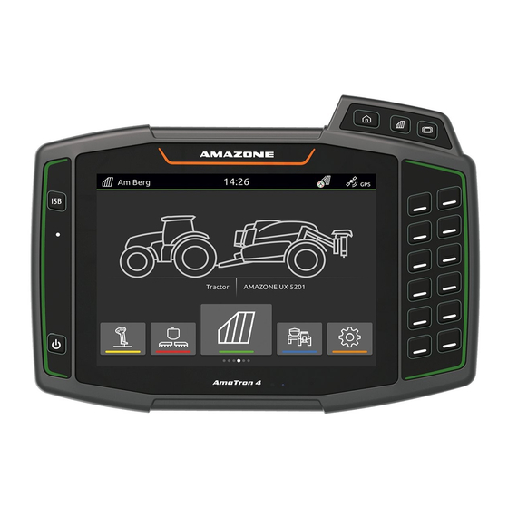
C | AmaTron 4 overview | AmaTron 4 overview CMS-T-00001632-A.1 Front view CMS-T-00001633-A.1 MG6010-EN-GB | G.1 | 13.12.2018... -
Page 12: Connections
C | AmaTron 4 overview | Connections 1 Button for the main menu 6 Selection buttons for implement controls 2 Button for the map view 7 On/Off button 3 Button for the Universal Terminal 8 Proximity sensor 4 ISB button... -
Page 13: D Operator Interface Overview
D | Operator interface overview | Operator interface overview CMS-T-00000210-C.1 Main menu CMS-T-00000234-B.1 Status bar Application carousel Display of the active implement and the active tractor MG6010-EN-GB | G.1 | 13.12.2018... -
Page 14: Application Carousel
D | Operator interface overview | Application carousel Application carousel CMS-T-00000254-B.1 The application carousel 1 contains the following applications: MG6010-EN-GB | G.1 | 13.12.2018... - Page 15 Show implement controls for the connected Universal Terminal implement AUX-N assignment Configure connected AUX-N input device Setup menu Configure AmaTron 4 Tractors and implements Configure tractors and implements Camera Show camera image Map view Open map view MG6010-EN-GB | G.1 | 13.12.2018...
-
Page 16: Map View
D | Operator interface overview | Map view Map view CMS-T-00000241-C.1 3.1 Map CMS-T-00000242-B.1 Select map layers Define the minimum zoom level Activate bird's-eye view Symbols for tractor and implement Focus on the tractor and implement Degree of overlap Compass GPS speed Define the maximum zoom level 10 Implement information... -
Page 17: Work Menu
D | Operator interface overview | Map view 3.2 Work menu CMS-T-00000243-C.1 Invert direction of travel Create track line Activate automatic part-width section control Create field boundary No function Create headland No function Create marking Open field menu 10 GPS drift correction 11 Create new field 12 GPS switch settings MG6010-EN-GB | G.1 | 13.12.2018... -
Page 18: Universal Terminal
D | Operator interface overview | Universal Terminal Universal Terminal CMS-T-00000236-B.1 Implement information Function keys NOTE The display within the Universal Terminal depends on the connected implement. MG6010-EN-GB | G.1 | 13.12.2018... -
Page 19: E Basic Operation
E | Basic operation | Basic operation CMS-T-00000181-D.1 Switching the AmaTron 4 on and off CMS-T-00000207-C.1 To switch on the AmaTron 4, press the on/off button 1 . NOTE If an AUX-N input device is connected, the assignment of the AUX-N input device must be confirmed;... -
Page 20: Using The Application Carousel
E | Basic operation | Switching between the applications 2.2 Using the application carousel CMS-T-00000252-B.1 1. In the main menu, scroll through the application carousel by swiping to the left or right. 2. Select the desired application. 2.3 Using swipe gestures CMS-T-00000260-C.1 NOTE The applications for swipe gestures can be selected in... -
Page 21: Configure Status Bar
E | Basic operation | Configure status bar Configure status bar CMS-T-00000197-B.1 The status bar 1 is shown in all of the applications. The information in the status bar can be configured. 1. Touch the status bar for 2 seconds. All of the information will be shown in an overview. -
Page 22: Entering Numerical Values
E | Basic operation | Entering numerical values 1. Swipe from the top edge of the display towards the middle. The quick-start menu will be opened. 2. Select the desired function. To close the quick-start menu, touch the display underneath the quick-start menu. Entering numerical values CMS-T-00000204-B.1 When a numerical value must be entered, a numeric... -
Page 23: Enter Text
E | Basic operation | Enter text Enter text CMS-T-00000205-B.1 If text must be entered, a key pad is opened. To enter digits or special characters, select To call up other special characters, select Confirm the entry with To cancel the entry, touch the display above the numeric keypad. -
Page 24: Entering The Basic Settings
F | Entering the basic settings | Entering the basic settings CMS-T-00000182-C.1 Activating the dynamic button bar CMS-T-00000211-C.1 When this function is activated, the button bar is automatically hidden in the map view after 10 seconds. When the user moves their hand on the display, the button bar is shown again. - Page 25 "Mirror camera horizontally" or "Mirror camera vertically". Activating the ignition switch CMS-T-00000214-C.1 When the ignition switch is activated, the AmaTron 4 is switched on and off with the tractor ignition. 1. In the Setup menu, select "Basic settings". MG6010-EN-GB | G.1 | 13.12.2018...
-
Page 26: Setting The Date And Time
F | Entering the basic settings | Setting the date and time 2. Activate "Ignition switch" deactivate. Setting the date and time CMS-T-00001685-B.1 1. In the Setup menu, select "Basic settings" > "Date and time". 2. Enter the desired date under "Date". 3. - Page 27 F | Entering the basic settings | Changing the language and region settings Changing the language and region settings CMS-T-00000216-C.1 1. In the Setup menu, select "Basic settings" > "Region and language". 2. Select the desired language under "Language". 3. Select the desired decimal separator under "Decimal separator".
-
Page 28: Setting The Display Brightness
F | Entering the basic settings | Setting the display brightness 2. Adjust the volume using the slider. Setting the display brightness CMS-T-00000221-C.1 1. In the Setup menu, select "Basic settings". 2. Adjust the display brightness using the slider. MG6010-EN-GB | G.1 | 13.12.2018... -
Page 29: Showing When The Display Is Touched
F | Entering the basic settings | Showing when the display is touched Showing when the display is touched CMS-T-00000223-C.1 When this function is activated, a white circle is shown at the point of contact every time the display is touched. 1. - Page 30 F | Entering the basic settings | Activating swipe gesture applications 1. In the Setup menu, select "Basic settings" > "Applications for swipe gestures". 2. Activate the desired applications. deactivate. MG6010-EN-GB | G.1 | 13.12.2018...
-
Page 31: Setting Up The Gps Receiver
G | Setting up the GPS receiver | Setting up the GPS receiver CMS-T-00001689-B.1 Setting up the A100/A101 receiver CMS-T-00001692-B.1 This GPS receiver provides the option of setting both correction satellites manually. The correction satellites send correction data to the receivers. The correction data increase the accuracy. -
Page 32: Setting Up The Ag-Star Receiver
G | Setting up the GPS receiver | Setting up the Ag-Star receiver With the "Automatic" setting, the GPS receiver automatically searches for the correct satellites. If the GPS receiver should send the NMEA 2000 data to the CAN bus, activate "NMEA 2000 (CAN)". -
Page 33: Resetting The Gps Receiver To Factory Settings
G | Setting up the GPS receiver | Resetting the GPS receiver to factory settings REQUIREMENTS Ag-Star receiver is connected 1. In the Setup menu, select "GPS receiver". 2. Under "Baud rate", select "Automatic". 3. Select "Configure GPS receiver". 4. Under "Correction mode", select the desired correction mode. - Page 34 G | Setting up the GPS receiver | Resetting the GPS receiver to factory settings 3. Select "Factory settings". 4. Confirm reset with MG6010-EN-GB | G.1 | 13.12.2018...
-
Page 35: Configuring Isobus
The AmaTron 4 has a clear identification number for the job documentation, TC number. If the job documentation should be saved on the AmaTron 4, the TC number must match with the TC number of the implement. If the AmaTron 4 is the only connected terminal, the implement automatically adopts the TC number of the AmaTron 4. -
Page 36: Managing Licenses
AMAZONE. Licence management can be used to activate the 5 applications on the AmaTron 4, to be able to use these applications permanently. The following table shows an overview of the functions that are activated with the licences. - Page 37 I | Managing licenses | GPS switch GPS switch GPS maps & Functions No licence GPS track AmaCam basic Displaying the map alignment Displaying existing geo- elements Automatic part-width section control with a maximum of 16 part-width sections Automatic part-width section control with a maximum of...
- Page 38 I | Managing licenses | GPS switch GPS switch GPS maps & Functions No licence GPS track AmaCam basic Shape application maps Creating track lines and beds Show camera image 1. In the Setup menu, select "License management". In the list of applications, the remaining period of use is displayed for each license or whether the application is activated or deactivated.
-
Page 39: Resetting To Factory Settings
J | Resetting to factory settings | Resetting to factory settings CMS-T-00001736-B.1 1. In the Setup menu, select "Service" > "Factory settings". The following application areas can be reset: Terminal settings: Resets all settings on the AmaTron Implement management: Deletes all created tractors and implements Documentation: Deletes all job data Saved pools: Deletes the saved views of the... -
Page 40: K Configuring Implements
K | Configuring implements | Configuring implements CMS-T-00000194-D.1 Configuring ISOBUS implements CMS-T-00000319-C.1 Connected ISOBUS implements are automatically created and the implement data is loaded. The implement data can only be changed through the Universal Terminal in the implement controls. For correct representation in the map view, the implement modelling must be specified. -
Page 41: Creating Non-Isobus Implements
K | Configuring implements | Configuring non-ISOBUS implements NOTE If the GPS receiver is installed on the implement, the position of the GPS receiver must be entered through the implement geometry. A: Transverse offset of the GPS receiver relative to the attachment point B: Longitudinal offset of the GPS receiver relative to the attachment point... - Page 42 K | Configuring implements | Configuring non-ISOBUS implements 2.2 Configuring non-ISOBUS implements CMS-T-00000322-D.1 1. In the main menu, select 2. Select the desired implement under "Implements". For correct representation in the map view, the implement modelling must be specified. The specifications depend on the following factors: whether the connected implement is mounted or towed.
-
Page 43: Renaming Implements
K | Configuring implements | Renaming implements 7. Enter the number of part-width sections of the connected implement under "Number of part-width sections". 8. Change the width for all of the part-width sections under "Width of the standard part-width sections". If the part-width sections have different widths, the width for each part-width section can be entered separately. -
Page 44: Deleting Implements
K | Configuring implements | Deleting implements Deleting implements CMS-T-00000355-C.1 1. In the main menu, select 2. select 3. Select the desired implement. The selected implement name becomes orange. 4. Delete the implement with Cancel with Selecting implements CMS-T-00000378-D.1 If non-ISOBUS implements are connected, the implements must be selected so that the correct implement data can be loaded. - Page 45 K | Configuring implements | Selecting implements 1. In the main menu, select 2. Select the desired implement. The selected implement is marked with a checkmark. MG6010-EN-GB | G.1 | 13.12.2018...
-
Page 46: Configuring Tractors
L | Configuring tractors | Configuring tractors CMS-T-00000195-C.1 Creating new tractors CMS-T-00000238-C.1 1. In the main menu, select 2. Under "Tractors", select 3. Enter the tractor name. 4. Confirm with Changing the tractor geometry data CMS-T-00000237-C.1 With the tractor geometry data, the position of the GPS receiver relative to the longitudinal axis, rear axle and to the attachment point on the tractor are specified. -
Page 47: Configuring The Tractor Sensors
L | Configuring tractors | Configuring the tractor sensors 1. In the main menu, select 2. Select the desired tractor. If the geometry data sent by an ISOBUS tractor should be changed, deactivate "Adopt geometry data". 4. Select "Geometry". 5. Under "A", enter the distance from the GPS receiver to the longitudinal axis of the tractor. -
Page 48: Configuring Radar Sensors
L | Configuring tractors | Configuring the tractor sensors 1. In the main menu, select 2. Select the desired tractor under "Tractors". 3. Select "Sensors". 4. Select "Wheel". If the wheel sensor signal should be used, activate "Send signal". If the wheel sensor signal should be simulated by the GPS signal, select "GPS receiver"... -
Page 49: Activating Gps Nmea2000
L | Configuring tractors | Configuring the tractor sensors 1. In the main menu, select 2. Select the desired tractor under "Tractors". 3. Select "Sensors". 4. Select "Radar". If the radar sensor signal should be used, activate "Send signal". If the radar sensor signal should be simulated by the GPS signal, select "GPS receiver"... -
Page 50: Configuring The Pto Shaft Sensor
L | Configuring tractors | Configuring the tractor sensors 1. In the main menu, select 2. Select the desired tractor under "Tractors". 3. Select "Sensors". 4. Select "GPS/NMEA2000". If the speed signal should be sent to the connected implement through the NMEA2000 protocol, activate "Send signal". -
Page 51: Configuring The Working Position Sensor
L | Configuring tractors | Configuring the tractor sensors 1. In the main menu, select 2. Select the desired tractor under "Tractors". 3. Select "Sensors". 4. Select "PTO shaft". If the PTO shaft speed should be sent, select "Send signal". 6. - Page 52 3.5.2 Configuring analogue working position sensors CMS-T-00000313-C.1 If an analogue working position sensor is connected, the AmaTron 4 can determine if the implement is in working position based on the voltage values. To do so, the voltage values for the different positions must be taught- in on the AmaTron 4.
-
Page 53: Renaming Tractors
L | Configuring tractors | Renaming tractors 10. Select "Teach-in lower end position". NOTE The value for the upper end position is evaluated as "Working position off". The value for the lower end position is evaluated as "Working position on". 11. -
Page 54: Deleting Tractors
L | Configuring tractors | Deleting tractors Deleting tractors CMS-T-00000306-C.1 1. In the main menu, select 2. select 3. Select the desired tractor. The selected tractor name becomes orange. 4. Delete with Cancel with MG6010-EN-GB | G.1 | 13.12.2018... -
Page 55: M Using The Map View
M | Using the map view | Using the map view CMS-T-00000188-C.1 Toggling the button bar CMS-T-00000206-C.1 Within the Work menu, the terminal functions and the functions of various implements can be displayed. The implements for which the functions are displayed can be selected. -
Page 56: Showing And Hiding The Implement Information
Start the swipe gesture at the edge of the display. 4. Press the button for the map view on the AmaTron 4 Swipe from the right edge of the screen towards the Work menu. NOTE... -
Page 57: Switching To Bird's-Eye View
GPS drift results from the use of correction sources with low precision. GPS drift can be recognised when the vehicle symbol on the AmaTron 4 no longer corresponds to the actual position of the vehicle. MG6010-EN-GB | G.1 | 13.12.2018... - Page 58 M | Using the map view | GPS drift correction 1. In the Work menu, select 2. Move the map using the arrows. To enter a value by which the map should be moved, tap the length specifications. 3. Confirm with MG6010-EN-GB | G.1 | 13.12.2018...
-
Page 59: N Map View Configuration
N | Map view configuration | Map view configuration CMS-T-00000192-C.1 Activate warnings CMS-T-00000225-C.1 If warnings are activated, warnings will be issued for the following events: Proximity to a field boundary Proximity to an obstacle Proximity to a headland 1. In the Work menu >... -
Page 60: Automatically Creating A Safety Zone
N | Map view configuration | Automatically creating a safety zone NOTE If "Tractor + GPS" is selected and the tractor does not send any signals, the GPS signal will be used. 1. In the Work menu > select "Basic settings". 2. -
Page 61: Configuring The Automatic Zoom
N | Map view configuration | Configuring the automatic zoom Configuring the automatic zoom CMS-T-00000228-C.1 When auto-zoom is activated, the map will be automatically zoomed for the following events: Zoomed in: Proximity to a field boundary Proximity to a headland Proximity to an obstacle Proximity to a worked area Speed under 3 km/h... -
Page 62: Defining The Map Layers
N | Map view configuration | Defining the map layers 7. Diminish the map with your fingers to the lowest desired zoom level. 8. select NOTE As long as autozoom is activated, the zoom levels can be adjusted at any time. Defining the map layers CMS-T-00000358-B.1 The following layers can be shown or hidden on the... -
Page 63: O Working Without Documentation
If a field has been worked and the current recording is available, a new field must be created on the AmaTron 4 to be able to work a different field. The recordings include the following data:... -
Page 64: P Working With Documentation
P | Working with documentation | Working with documentation CMS-T-00000263-D.1 Creating a new field CMS-T-00000325-C.1 With the documentation on the AmaTron 4, the focus is on the field. When a field has been created, the following data is automatically saved with the field: Field boundaries... -
Page 65: Importing Iso-Xml Job Data
"Taskdata" in the "Taskdata" folder in the main folder of the USB flash drive 1. Open the quick-start menu. 2. select ISO-XML The AmaTron 4 imports the job data from the USB flash drive. MG6010-EN-GB | G.1 | 13.12.2018... -
Page 66: Loading Iso-Xml Field Data
P | Working with documentation | Loading ISO-XML field data Loading ISO-XML field data CMS-T-00000340-C.1 To be able to use imported and created field data, the field data needs to be loaded. REQUIREMENTS ISO-XML job data is imported, see page 63 1. -
Page 67: Importing Field Data From A Shape File
P | Working with documentation | Importing field data from a shape file Application maps are contained in the job data and are loaded with the job data. To adjust an application map, select the desired application map in the selected job. -
Page 68: Creating A New Job
P | Working with documentation | Creating a new job 3. In the menu for selecting the field data, select The application maps saved on the USB flash drive are displayed 4. Select the desired application map. To adjust the units for the application rate, select "Unit". -
Page 69: Managing Products
P | Working with documentation | Managing products 1. In the Work menu, select 2. Select the field. 3. Under "Jobs", select 4. Enter the job name. 5. Confirm with NOTE The following data can be assigned to a job: Products;... - Page 70 P | Working with documentation | Managing products 1. In the Work menu, select 2. Select the field. 3. Select the desired job under "Jobs". 4. Select "Product". On the left side, the setpoint receivers of the connected implement are listed. 5.
- Page 71 P | Working with documentation | Managing products To create a new product, select 8. Enter the name for the product under "Product name". 9. Enter the units for the product under "Units". 10. Confirm with To assign a product, select the desired products under "Products".
-
Page 72: Managing The Customers
P | Working with documentation | Managing the customers Managing the customers CMS-T-00000335-C.1 REQUIREMENTS The job data is imported, see page 63 or the field is created, see page 62 The job is created; see page 66 or imported with the job data 1. -
Page 73: Managing Drivers
P | Working with documentation | Managing drivers To create a new customer, select 6. Enter the customer data. 7. Confirm with To assign the job to a customer, select the desired customer. The selected customer is marked with a checkmark. 9. - Page 74 P | Working with documentation | Managing drivers 1. In the Work menu, select 2. Select the field. NOTE To create a driver, a random job must be created and selected. The created driver can then be assigned to any job. 3.
-
Page 75: Exporting Iso-Xml Job Data
P | Working with documentation | Exporting ISO-XML job data To assign a driver to a job, select the desired driver. The selected driver is marked with a checkmark. 9. Confirm with Exporting ISO-XML job data CMS-T-00001743-A.1 Recorded job data can be exported as ISO-XML job data and saved to a USB flash drive. -
Page 76: Using Part-Width Section Control
Q | Using part-width section control | Using part-width section control CMS-T-00000189-D.1 Overlap, setting CMS-T-00000286-C.1 1.1 Defining the overlap in the direction of travel CMS-T-00000287-C.1 The overlap in the direction of travel indicates how far the part-width sections can protrude over a boundary in the direction of travel before the part-width sections are switched off. -
Page 77: Defining The Degree Of Overlap
Q | Using part-width section control | Overlap, setting 1. In the Work menu > select "Overlap". 2. Select "Overlap in the direction of travel when switching on" and "Overlap in the direction of travel when switching off". 3. Enter a value between -1,000 cm and 1,000 cm. 4. - Page 78 Q | Using part-width section control | Overlap, setting Possible settings: Explanation Figure The part-width sections are switched off before any overlap occurs. The part-width sections are 50 % switched off when they half protrude over a boundary. The part-width sections are 100 % switched off when they fully protrude over a boundary.
-
Page 79: Defining The Overlap Tolerance
Q | Using part-width section control | Overlap, setting 1. In the Work menu > select "Overlap". 2. Select "Degree of overlap". 3. Select the percent value. 4. Confirm with 1.3 Defining the overlap tolerance CMS-T-00000289-C.1 The overlap tolerance defines how far the outer part- width sections can protrude over a worked area before they are switched off. -
Page 80: Defining The Overlap Tolerance At The Field Boundary
Q | Using part-width section control | Overlap, setting 1. In the Work menu > select "Overlap". 2. Select "Overlap tolerance". 3. Enter a value between 0 cm and 150 cm. 4. Confirm with 1.4 Defining the overlap tolerance at the field boundary CMS-T-00000290-C.1 The overlap tolerance at the field boundary defines how far the outer part-width sections can protrude over the... -
Page 81: Starting A Recording
Starting a recording CMS-T-00000264-C.1 When the recording has been started and the part-width sections are switched on, the AmaTron 4 saves the position data of the worked area. Worked areas are shown in green in the map view. The recordings include the following data:... - Page 82 Q | Using part-width section control | Starting a recording When the connected implement supports automatic part-width section control, select in the Work menu When the part-width sections of the connected implement are switched manually, select in the Work menu. The following table shows an overview of the part- width section status and the corresponding colours of the part-width sections in the implement symbol.
-
Page 83: Terminating A Recording
Q | Using part-width section control | Terminating a recording Terminating a recording CMS-T-00000265-B.1 When the connected implement supports automatic part-width section control, switch all of the part-width sections off using the implement controls Stop When the part-width sections of the connected implement are switched manually, select in the Work menu. -
Page 84: R Managing The Field Boundaries
CMS-T-00001745-A.1 Creating the field boundary CMS-T-00000298-B.1 The AmaTron 4 can create a field boundary from the worked area. The AmaTron 4 can calculate the size of the field from the field boundary. The worked area and the remaining area result from the field size. -
Page 85: Editing Field Boundaries
R | Managing the field boundaries | Editing field boundaries Editing field boundaries CMS-T-00000308-B.1 1. Tap on the field boundary. To rename the field boundary, select To delete the field boundary, select MG6010-EN-GB | G.1 | 13.12.2018... -
Page 86: Managing Headlands
S | Managing headlands | Managing headlands CMS-T-00001746-B.1 Creating headlands CMS-T-00000300-C.1 REQUIREMENTS Field boundary has been created, see page 82 1. In the Work menu, select 2. Enter the headland width. NOTE When the first track line is laid on the field boundary, the second track line lies one working width away from the field boundary inside the field. -
Page 87: Editing The Headlands
S | Managing headlands | Editing the headlands NOTE When the first track line is not laid on the field boundary, the first track line lies half of the working width away from the field boundary inside the field. If the first track line should not be laid on the field boundary, deactivate "First track line on the field boundary". -
Page 88: T Marking Obstacles
If there are obstacles on the field, such as water holes, electricity pylons, boulders or trees, these obstacles can be marked on the map of the AmaTron 4. If the vehicle is moving towards an obstacle, a warning is issued and the screen zooms onto the vehicle symbol. - Page 89 T | Marking obstacles | If the obstacle symbol should be deleted, select To set the obstacle symbol, tap on any spot on the map. MG6010-EN-GB | G.1 | 13.12.2018...
-
Page 90: Parallel Driving
U | Parallel driving | Parallel driving CMS-T-00000190-D.1 Configuring parallel driving CMS-T-00000231-C.1 1.1 Adjusting the light bar sensitivity CMS-T-00000291-C.1 The light bar 1 shows the deviation of the tractor from the closest track line and supports the driver in staying on track. -
Page 91: Selecting The Track Line Pattern
U | Parallel driving | Configuring parallel driving 1.2 Selecting the track line pattern CMS-T-00000293-C.1 With the AmaTron 4, different types of track lines can be recorded. Available track line Explanation Figure patterns Straight track line that is laid between 2 points. -
Page 92: Creating Track Lines
U | Parallel driving | Creating track lines Creating track lines CMS-T-00001688-B.1 2.1 Creating an A-B line CMS-T-00000296-C.1 REQUIREMENTS "A-B" track line pattern is selected, see page 89 1. Drive to the beginning of the row. 2. select The start point of the track line is set on the vehicle position. -
Page 93: Creating Beds
U | Parallel driving | Creating beds 1. Drive to the beginning of the row. 2. select The start point of the track line is set on the vehicle position. 3. Drive to the end of the row. NOTE The end point of the track line must be at least 15 m away from the start point. -
Page 94: Using A Light Bar
U | Parallel driving | Using a light bar 1. In the Work menu > select "Parallel driving" > "Beds". 2. Enter a value between 1 and 20. 3. Confirm with The track lines will be highlighted in the specified rhythm. - Page 95 U | Parallel driving | Using a light bar REQUIREMENTS Light bar added to the status bar; see page 19 Track lines are created; see page 90 Light bar sensitivity is defined; see page 88 To keep the vehicle on the track, steer the vehicle by the displayed distance towards the track line.
-
Page 96: Using Automatic Boom Lowering
NOTE The value to be entered refers to the time at which the AmaTron 4 lowers the boom before the unworked area is reached. The value for the time of the lowering procedure must be determined manually. - Page 97 V | Using automatic boom lowering | 1. In the Work menu > select "Automatic boom lowering". 2. Activate "Automatic boom lowering". 3. Under "Delay for boom lowering", enter the duration of the lowering procedure in seconds. 4. Confirm with MG6010-EN-GB | G.1 | 13.12.2018...
-
Page 98: W Configuring Aux-N Input Devices
Configuring AUX-N input devices CMS-T-00000359-B.1 Setting up AUX-N input devices CMS-T-00000324-B.1 Using the AmaTron 4, the buttons of AUX-N input devices can be assigned. Therefore, implement functions and AmaTron 4 functions can be actuated with the AUX-N input device. NOTE Only AUX-New input devices can be assigned with functions using the AmaTron 4. - Page 99 W | Configuring AUX-N input devices | Setting up AUX-N input devices The AUX-N input device is shown symbolically together with the selected button. The keys that represent the connected implements and the AmaTron 4 are shown underneath. With these keys, the implement functions and the terminal functions can be opened.
-
Page 100: Managing Preferred Assignments
2.1 Confirming the AUX-N assignment CMS-T-00000360-B.1 When an AUX-N input device is connected, the AUX-N assignments for the connected implement must be confirmed each time the AmaTron 4 is restarted. The menu for the "Preferred assignment" is automatically opened. 1. Check the AUX-N assignment. - Page 101 W | Configuring AUX-N input devices | Managing preferred assignments buttons of an AUX-N input device can be assigned to these functions. If the functions are not listed on the left side: select 2. Select a function from the list. A list of available AUX-N input devices will be shown.
- Page 102 W | Configuring AUX-N input devices | Managing preferred assignments In the overview, the button is assigned to the selected function. 6. Assign other buttons Confirm the AUX-N assignment with 2.2.2 Changing the AUX-N assignment using the input list CMS-T-00000363-B.1 For the AUX-N assignment using the input list, all of the available buttons are listed on the left side.
- Page 103 W | Configuring AUX-N input devices | Managing preferred assignments 3. Select the desired implement. An overview of available functions is shown. 4. Select the desired function. The selected function is shown beside the button. 5. Confirm with In the overview, the button is assigned to the selected function.
- Page 104 W | Configuring AUX-N input devices | Managing preferred assignments Confirm the AUX-N assignment with 2.2.3 Deleting the AUX-N assignment CMS-T-00000364-B.1 1. In the function list or input list, select 2. Select the desired functions. 3. Confirm with MG6010-EN-GB | G.1 | 13.12.2018...
-
Page 105: Using The Universal Terminal
The keys for the implement controls can be directly actuated by touch or using the buttons on the right side of the AmaTron 4. The arrangement of the buttons corresponds to the representation of the keys on the user interface. -
Page 106: Y Taking Screenshots
Y | Taking screenshots | Taking screenshots CMS-T-00000201-B.1 A screenshot refers to an image of the current display on the screen. The image is saved to the USB flash drive as a graphic file. The file name is composed of the current date and time. -
Page 107: Z Using The Camera
Z | Using the camera | Using the camera CMS-T-00000323-C.1 The AmaTron 4 can show images from a connected camera. REQUIREMENTS Camera is connected Camera is configured; see page 23 In the main menu, select The camera image is displayed. -
Page 108: Indexes
| INDEX | INDEX using Changing the implement modelling Address see Configuring non-ISOBUS implements Technical editing Changing the implement type AmaCam see Configuring non-ISOBUS implements enabling Changing the system of units Antenna position Configuring the implement Application carousel see Configuring non-ISOBUS implements Overview Configuring the working width using... - Page 109 | INDEX | Gesture controls Managing licenses configuration GPS drift Overview GPS maps & docs Map view enabling opening Overview GPS receiver Entering the position Menu buttons Position GPS switch enabling Non-ISOBUS implement configuration GPS track creating enabling Obstacle Headlands Overlap Implement geometry see Configuring non-ISOBUS implements...
- Page 110 | INDEX | Setting the time zone Work menu Overview Setup menu showing opening Shape file Import data Zoom configuration Softkey bar showing using Speed signal Status bar configuration Swipe gestures configuration Switch on day mode Switch on night mode Track guidance enabling using...
- Page 111 AMAZONEN-WERKE H. DREYER GmbH und Co. KG Postfach 51 D-49202 Hasbergen-Gaste Germany Telefon +49 (0) 5405 501-0 E-Mail amazone@amazone.de Internet www.amazone.de...
Need help?
Do you have a question about the AmaTron 4 and is the answer not in the manual?
Questions and answers
Здравствуйте можно ли стоя на одном месте когда промываешь бочку чтобы вылив из форсунок был такой же когда в рабочем движении