Amazone AMATRON 3 Operating Instructions Manual
Control terminal
Hide thumbs
Also See for AMATRON 3:
- Operating manual (98 pages) ,
- Operating instructions manual (148 pages)

Subscribe to Our Youtube Channel
Related Manuals for Amazone AMATRON 3


Summary of Contents for Amazone AMATRON 3
- Page 1 Operating instructions MG5560-EN-II | B.1 | 22.07.2016 Control terminal AMATRON 3 Original operating instructions...
-
Page 3: Table Of Contents
2.3 Deleting the selected AUX-N Mounting for AMABUS mode assignment 2.4 Deleting all AUX-N assignments Mounting for parallel operation Using the licence management C AMATRON 3 overview Using the diagnosis Front side 4.1 Using USB management 4.2 Using the pool management Rear side 4.3 Using the CAN diagnosis... - Page 4 | TABLE OF CONTENTS | Managing master data 3.11 Checking the switch-on and -off times 2.1 Managing setpoints Zooming the map 2.2 Managing fields Panning the map 2.3 Managing the customers 2.4 Managing workers Turning around the orientation of the tractor symbol 2.5 Managing products Marking obstacles...
- Page 5 | TABLE OF CONTENTS | L Using the AUX-N menu M Eliminating faults N Maintenance Performing the software update Indexes GLOSSARY INDEX MG5560-EN-II | B.1 | 2016.07...
-
Page 6: A About This Operating Manual
A | About this operating manual | About this operating manual 020869 Meaning of the operating manual 020879 The operating manual is an important document and a part of the electronic product. 1. Before starting work, read and observe the respec- tive sections of the operating manual. -
Page 7: Diagrams
A | About this operating manual | Diagrams Diagrams 021149 4.1 Notes 021152 NOTE Indicates practical tips and instructions that will help you to make optimal use of all the functions of your implement. 4.2 Instructions 021150 Numbered instructions 021156 Actions that have to be performed in a chronological se- quence are represented as numbered instructions. -
Page 8: Lists
A | About this operating manual | Diagrams Instructions without sequence 021155 Instructions that do not require a specific sequence are shown as a list with tilted arrows. Action Action Action 4.3 Lists 007273 Lists are used, for example, to show different selection options. -
Page 9: Your Opinion Is Important
Your suggestions for improvement help us to create ever more user-friendly operating manuals. Please send us your suggestions by post, fax or email: AMAZONEN-WERKE H. DREYER GmbH & Co. KG P.O. Box 51 D-49202 Hasbergen Fax: +49 (0) 5405 501-234 Email: td@amazone.de MG5560-EN-II | B.1 | 2016.07... -
Page 10: B Assembly Instructions
018762 1. Mount the GPS receiver on the tractor, please refer to the operating manual for the GPS receiver. The AMATRON 3 control terminal can be connec‐ ted to the tractor basic equipment or with the ISO‐ BUS wiring. The tractor basic equipment (console with distribu-... -
Page 11: Mounting For Isobus Mode
B | Assembly instructions | Mounting for ISOBUS mode Mounting for ISOBUS mode 018763 For implements that are connected to an ISOBUS tractor using the ISOBUS light cabling: Disable the ISOBUS function of the tractor terminal. MG5560-EN-II | B.1 | 2016.07... -
Page 12: Mounting For Amabus Mode
B | Assembly instructions | Mounting for AMABUS mode Mounting for AMABUS mode 018764 MG5560-EN-II | B.1 | 2016.07... -
Page 13: Mounting For Parallel Operation
B | Assembly instructions | Mounting for parallel operation Mounting for parallel operation 018765 MG5560-EN-II | B.1 | 2016.07... -
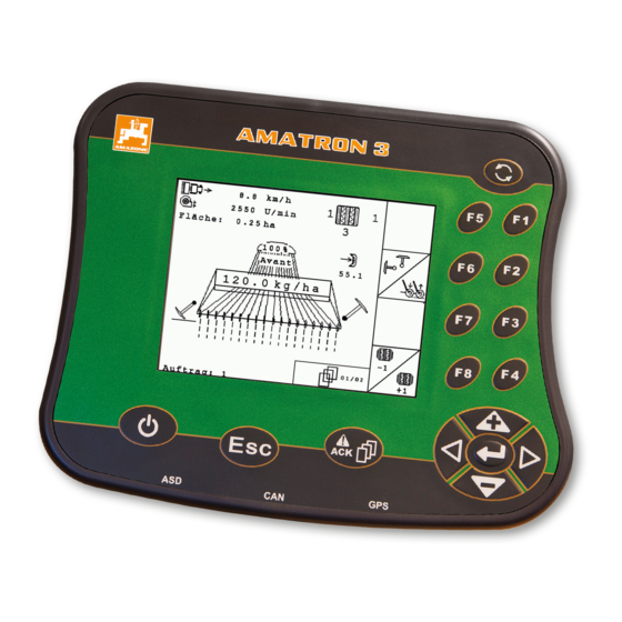
Page 14: C Amatron 3 Overview
2 F keys: Press the buttons on the display 5 Escape: Back, cancel 3 Directional pad: Change the selection on the display, 6 On/Off button: Switching the AMATRON 3 on and off change numerical values, confirm selections MG5560-EN-II | B.1 | 2016.07... -
Page 15: Rear Side
C | AMATRON 3 overview | Rear side Rear side 020887 Shift key 021015 1 Shift key for the work menu of the implement controls Rating plate and CE mark 021014 The following information is listed on the rating plate: 1 Implement ID no. -
Page 16: D Basic Operation
D | Basic operation | Basic operation 021082 Using the toggle button 006867 The toggle button 1 can be used to switch among the selected menus. To switch among the selected menus consecutively, press briefly. To switch to the main menu, press and hold. -
Page 17: Using The Directional Pad
D | Basic operation | Using the F keys Using the F keys 006868 The arrangement of the keys "F1" to "F8" corresponds to the arrangement of the buttons on the display. When ex- plaining the procedures, this operating manual uses the symbols on the buttons. -
Page 18: Entering Numerical Values
D | Basic operation | Entering numerical values Text menu overview : Move the curser left and right : Deletes the character in front of the curser : Switch between upper and lower case letters : Shows letters with accents : Clears the input field 1. -
Page 19: Using The Shift Key
When the shift key is active, it is shown on the display. Press on the rear side of the AMATRON 3. Other function field will be shown, which changes the assignment of the function keys. MG5560-EN-II | B.1 | 2016.07... -
Page 20: E After Switching On
E | After switching on | After switching on 006865 Selecting the BUS mode 009911 After starting the AMATRON 3, it is possible to select be- tween 2 BUS modes. The selection of the BUS mode depends on the connected implement. BUS modes: AMABUS... -
Page 21: Checking The Aux-N Assignments
The set BUS mode is shown in the main menu 1 . Checking the AUX-N assignments 009912 Each time the AMATRON 3 is restarted, the assignment of the external input devices must be checked and con- firmed for safety reasons. The AMATRON 3 only recog- nises external input devices in ISOBUS mode. -
Page 22: Changing The Aux-N Assignments
E | After switching on | Changing the AUX-N assignments Changing the AUX-N assignments 009913 1. Select a desired function from the list with A list with the input buttons will be opened. 2. Select a desired input button with The input button is assigned to the selected function. -
Page 23: Main Menu Overview
F | Main menu overview | Main menu overview 009637 Time and date Selected implement Selected tractor Started job Activated GPS applications with remaining time in hours : Opens the GPS switch. Using the GPS switch, see page 72 : Opens the implement controls. The symbol varies depending on the connected implement. -
Page 24: Configuring The Setup
G | Configuring the setup | Configuring the setup 006870 Select Main menu > "Setup". The setup menu will be opened. Entering the settings 006876 Select "Setup" > "Settings". The "Settings" menu will be opened. MG5560-EN-II | B.1 | 2016.07... -
Page 25: Entering The Basic Settings
Possible settings: : Enabling or disabling job management, see page 23 : Defines whether the AMATRON 3 should be switched on and off together with the vehicle ignition, see page 24 : Setting the volume of the signal tones and alarm... - Page 26 Possible settings: : When the vehicle ignition is switched on or off, the AMATRON 3 is switched on or off. : The AMATRON 3 must be switched on and off manually. 2. Enable or disable ignition switching 1.1.3 Adjusting the volume...
- Page 27 1. Select "Setup" > "Settings" > "Basic settings" > "Vol- ume". 2. Enter a value between 1 and 20. 3. Confirm the entry. NOTE The AMATRON 3 cannot be muted. 1.1.4 Setting the brightness 006886 Select "Setup" > "Settings" > "Basic settings" > "Brightness".
- Page 28 G | Configuring the setup | Entering the settings 1.1.5 Setting the date and time 006892 Select "Setup" > "Settings" > "Basic settings" > "Date and time". Possible settings: : Day, month and year for the current date : Hours and minutes for the current time : Value between -13 and +12 for the corresponding time zone : 24-hour format or 12-hour format...
-
Page 29: Configuring Isobus
AMATRON 3, the Task Controller ID must match with the Task Controller ID of the implement. If the AMATRON 3 is the only con- nected terminal, the implement automatically adopts the Task Controller ID of the AMATRON 3. -
Page 30: Setting Up The Interfaces
If the connected tractor does not send any geometry or sensor data or if the tractor data should not be used, the AMATRON 3 can simulate a tractor. The AMATRON 3 has a clear identification number for the simulated trac- tor, the TC-ID TECU. - Page 31 G | Configuring the setup | Entering the settings 1.3.1 Setting up the GPS receiver 006902 Depending on the utilised GPS receiver, the correspond- ing settings must be entered here. REQUIREMENTS GPS receiver is connected; Light bar is deactivated Select "Setup" > "Settings" > "Interfaces" > "GPS". GPS menu overview : Call up the GPS information, e.g.
- Page 32 G | Configuring the setup | Entering the settings Setting up the AG-STAR/SMART6 receiver 017824 1. Select "GPS driver" > "AG-STAR/SMART6". 2. Under "Correction signal", select the desired correc- tion signal. Possible settings: SBAS GPS SBAS GPS / GLONASS GPS / GLONASS 1 GPS / GLONASS 2 NOTE SBAS, Satellite Based Augmentation - satellite-based...
- Page 33 G | Configuring the setup | Entering the settings 1.3.2 Setting up the ASD interface 014001 The ASD interface can be used to transmit setpoints for the application rate from a sensor To be able to use these setpoints, the setpoints must be added to a job, see page 62.
-
Page 34: Configuring The Toggle Button
2. Select the menus that should be reached using the toggle button. 1.5 Defining the start mode 006884 The AMATRON 3 can be started in 3 different modes. Select "Setup" > "Settings" > "Start mode". MG5560-EN-II | B.1 | 2016.07... -
Page 35: Configuring Parallel Operation
(UT), see page 27. This menu defines which functions should be performed by the AMATRON 3. If for example two AMATRON 3 ter- minals are being used, one AMATRON 3 can be used to display the implement controls and the other AMATRON 3 for the GPS functions. -
Page 36: Defining The Aux-N Assignment Using The Functions List
G | Configuring the setup | Defining the AUX-N assignment TRON 3 functions can only be assigned to an external input device if the AMATRON 3 has the ISOBUS-UT number 1, see page 27. An example for such an exter- nal input device is the AmaPilot . -
Page 37: Defining The Aux-N Assignment Using The Input List
G | Configuring the setup | Defining the AUX-N assignment The list of available buttons will be opened. 3. Select a button from the list. The selected button is assigned to the function. 2.2 Defining the AUX-N assignment using the input list 007528 For the AUX-N assignment using the input list, all of the available buttons are listed on the left side. -
Page 38: Deleting The Selected Aux-N Assignment
G | Configuring the setup | Defining the AUX-N assignment 3. Select a function from the list. The button is assigned to the selected function. 2.3 Deleting the selected AUX-N assignment 013505 1. Select the desired assignment from the list. 2. -
Page 39: Deleting All Aux-N Assignments
2. Confirm with "Yes". The assignment will be deleted. Using the licence management 006878 3 applications can be run on the AMATRON 3: GPS switch for part-width section control GPS track for track guidance GPS maps for variable rate control with application... -
Page 40: Using The Diagnosis
G | Configuring the setup | Using the diagnosis License management can be used to activate the 3 ap- plications on the AMATRON 3, to be able to use these applications permanently. 1. Select "Setup" > "Settings" > "License manage- ment". -
Page 41: Using Usb Management
G | Configuring the setup | Using the diagnosis Possible selection: : Overview of the versions of the installed software : Use "USB management"; see page 39 : Use "Pool management"; see page 40 : Use "CAN diagnosis"; see page 41 : Perform a "Reset";... -
Page 42: Using The Pool Management
G | Configuring the setup | Using the diagnosis Deleting files or folders from the USB flash drive 007531 1. Select the desired file or folder from the list. 2. Select 3. Confirm with "Yes". The file or folder will be deleted. Saving data to a USB flash drive 007532 With this function, all of the recorded job data will be... -
Page 43: Using The Can Diagnosis
A list with the pools will be opened. 2. Select the pool. 3. Select 4. Confirm deleting. 5. Restart the AMATRON 3. 4.3 Using the CAN diagnosis 006909 CAN diagnosis is for the exclusive use of service em- ployees for maintenance purposes. -
Page 44: Performing A Reset
TRON 3 setting can be reset. 1. Select "Setup" > "Setting" > "Diagnosis" > "Reset". To reset the GPS switch settings, select "Reset GPS switch/track". To reset the AMATRON 3 settings and delete the data, select "Factory settings". 4. Confirm the reset. -
Page 45: Configuring Implements
To be able to use the GPS switch functions, the fol- lowing implements must be configured: AMABUS implements Implements that cannot communicate with the termi- Using the entered implement data, the AMATRON 3 can control the connected implement. The following implement data must be entered: Implement name... -
Page 46: Editing The Implement Data
H | Configuring implements | Editing the implement data Implement menu overview Existing implements Information on the selected implement : Opens the main menu : Adds an implement : Deletes the selected implement : Opens the implement data for the selected imple- ment, see page 44 Editing the implement data 006926... -
Page 47: Editing The Implement Geometry Data
H | Configuring implements | Editing the implement data 3. Enter a name for the implement under "Name". If an AMABUS implement is connected, select the connected implement under "Implement type". NOTE The implement type can only be selected if the AMA- TRON 3 was started in AMABUS mode, see page 18. -
Page 48: Selecting The Implement
H | Configuring implements | Selecting the implement 2. Under "X1", enter the distance between the coupling point and the application point. NOTE Application points: Field sprayers: Spray nozzles Fertiliser spreaders: Centre point of the spreading discs Seed drills: Rear seeding coulters 3. - Page 49 H | Configuring implements | Selecting the implement Selectable implements have a check box: Mark the desired implement. MG5560-EN-II | B.1 | 2016.07...
-
Page 50: Configuring Tractors
I | Configuring tractors | Configuring tractors 006874 For the AMATRON 3 to be able to control the connected implement properly, the data for the utilised tractor must be transmitted to the AMATRON 3. The following tractor data is required:... -
Page 51: Editing The Tractor Data
I | Configuring tractors | Editing the tractor data Tractor menu overview Available tractors Information on the selected tractor : Opens the main menu : Adds a tractor, see page 49 : Deletes the selected tractor : Opens the tractor data for the selected tractor for editing.see page 49 Editing the tractor data 007576... -
Page 52: Editing The Tractor Geometry Data
I | Configuring tractors | Editing the tractor data 1.1 Editing the tractor geometry data 007574 The implement geometry data is required for the GPS switch to function properly. The part-width section con- trol, track guidance and variable rate control depend on the correct geometry. -
Page 53: Configuring The Tractor Sensors
The tractor sensor must only be configured if the tractor does not have any speed sensors and therefore does not send speed data. In the case, the speed data can be transmitted to the AMATRON 3 by external sensors, e.g. wheel sensors or GPS sensors. REQUIREMENTS... -
Page 54: Selecting The Tractor
I | Configuring tractors | Selecting the tractor 2. Under "Speed source", enter the device used to de- termine the tractor speed. NOTE Only speed sources that are not yet signed in to the ISOBUS are shown. 3. Under "PTO shaft", enter the number of pulses sent by the PTO shaft with each rotation. -
Page 55: Using The Job Management
XML format. The ISO-XML jobs can be created with a Farm Management Information System (FMIS) and im- ported to the AMATRON 3 with a USB flash drive. Alter- natively, the jobs can be created and edited on the AMA- TRON 3. -
Page 56: Importing Jobs
J | Using the job management | Importing jobs Main menu > "Jobs". Job menu overview Existing jobs Information on the selected job : Opens the main menu : Opens the master data menu, see page 55 : Adds a job, see page 61 : Deletes the selected job : Starts or stops the selected job, see page 70 and see page 70... -
Page 57: Managing Master Data
Managing master data 007606 Master data is additional information that can be created and saved on the AMATRON 3. The created master data can be added to jobs. Master data from a Farm Manage- ment Information System (FMIS) cannot be edited. -
Page 58: Managing Setpoints
J | Using the job management | Managing master data NOTE The fields marked with a "*" are mandatory, and must be filled in. Examples of mandatory fields are "Set- points" or "Family name". 2.1 Managing setpoints 007602 Controllable implement elements can be assigned with setpoints. -
Page 59: Managing Fields
J | Using the job management | Managing master data 1. Select a setpoint from the list Add a new setpoint. The "Setpoint" menu will be opened. : Line for the total application/spread rate : Line for one product. 2. Enter the setpoints for the product in the first col- umn. -
Page 60: Managing The Customers
J | Using the job management | Managing master data Select "Jobs" > > "Fields". : Opens the master data menu : Adds a field : Deletes the selected field : Opens the search function; see page 69 2.2.1 Editing the field data 007613 1. -
Page 61: Managing Workers
J | Using the job management | Managing master data Customer menu overview Existing customers Information on the selected customer : Opens the master data menu : Adds a customer : Deletes the selected customer : Opens the search function 2.3.1 Editing the customer data 009332 1. -
Page 62: Managing Products
J | Using the job management | Managing master data Worker menu overview : Opens the master data menu : Adds a worker : Deletes the selected worker : Opens the search function 2.4.1 Editing worker data 009335 1. Select a worker from the list Add a new worker. -
Page 63: Creating A New Job
USB flash drive. Creating a new job 006928 With the AMATRON 3, jobs can be created in ISO-XML format and edited. The created jobs can be exported and further processed with a Farm Management Information System (FMIS). -
Page 64: Adding Setpoints To A Job
The setpoints for the application/spread rates can come from the following sources: Setpoints created on the AMATRON 3 From an imported application map in shape format From an external device using the ASD interface MG5560-EN-II | B.1 | 2016.07... - Page 65 J | Using the job management | Creating a new job 3.1.1 Adding created setpoints 018624 REQUIREMENTS Job is started, see page 70 If the setpoint should be taken from the master data: Setpoints are created in the master data, see page 56 If the setpoint should be taken from an applica- tion map in shape format:...
-
Page 66: Adding A Worker To A Job
The setpoints created in the master data will be shown. NOTE If no setpoints are available, the AMATRON 3 auto- matically opens the menu for creating a setpoint. In this case, see page 56. 4. Select the desired setpoint from the list. - Page 67 J | Using the job management | Creating a new job 1. Select "Jobs" > Started job. 2. Select The "Assign worker" menu will be opened. The al- ready assigned workers will be shown. : Working time recording started : Working time recording stopped : Opens the selected job : Adds a new worker : Start or stop the working time recording for...
-
Page 68: Adding Implements And Tractors To A Job
J | Using the job management | Creating a new job 4. Select the desired worker from the list. The selected worker will be added to the job. To start the working time recording for a worker: Select To stop the working time recording for a worker: Select 3.3 Adding implements and tractors to a job 012165... - Page 69 J | Using the job management | Creating a new job 1. Select "Jobs" > Started job. 2. Select The "Implement assignment" menu will be opened. The already assigned implements and tractors will be shown. : Working time recording started : Working time recording stopped : Opens the selected job : Opens the menu with the selectable implements...
-
Page 70: Checking The Map Type
If a job with an application map in ISO-XML format was imported from the Farm Management Information Sys- tem to the AMATRON 3, the map type is shown here. Map type 1: The application map is displayed in GPS switch and the setpoints are processed. -
Page 71: Searching For Jobs
J | Using the job management | Searching for jobs Searching for jobs 006930 1. Select Jobs > 2. Enter the search term. 3. Confirm the entry. The found jobs are displayed. Copying jobs 006931 To process jobs with the same data several times, the jobs can be copied. -
Page 72: Starting A Job
J | Using the job management | Starting a job The job will be copied and marked with a "*". Starting a job 006933 When a job is started, the job data is recorded. The field data stored in the job are shown on the map in GPS switch. -
Page 73: Exporting Jobs
J | Using the job management | Exporting jobs 1. "Jobs" > Select the current job. 2. Select The selected job will be stopped. Exporting jobs 006932 Exported jobs are saved to the USB flash drive. The ex- ported jobs can then be further processed with a Farm Management Information System (FMIS). -
Page 74: K Using The Gps Switch
K | Using the GPS switch| Using the GPS switch 013347 GPS switch overview 026186 1.1 GPS switch interface overview 013353 1.1.1 Symbols on the map 014003 MG5560-EN-II | B.1 | 2016.07... - Page 75 K | Using the GPS switch| GPS switch overview Field boundary warning "GPS" speed Compass Worked area and remaining area Worked area in light green, double-worked areas in Obstacle dark green 10 "Virtual" headlands in grey Tractor symbol and implement symbol 11 Track line with track line number Field boundary in red 12 Mode for the part-width section control...
- Page 76 K | Using the GPS switch| GPS switch overview 1.1.3 GPS switch menu 014005 Page 1 : Opens the main menu : Changes between Page 1 and Page 2 starts and stops the recording for a manual im- plement starts and stops the recording for an ISOBUS or AMABUS implement : Opens the "Field data"...
-
Page 77: Gps Switch Functions Overview
AMATRON 3. To achieve opti- mal coverage, the AMATRON 3 can automatically switch the part-width sections of the connected implement on and off. To do so, the AMATRON 3 uses the GPS signal from the connected GPS receiver. NOTE... -
Page 78: Gps Quality Requirements
K | Using the GPS switch| GPS switch overview 1.2.2 Track guidance with GPS track 013948 Track lines can be created on the AMATRON 3 to sup- port the driver in working the field seamlessly. After the track lines have been created, they are shown on the map. -
Page 79: Starting The Gps Switch
K | Using the GPS switch| Starting the GPS switch GPS quality HDOP 0 to 6 Medium HDOP 6 to 8 Poor HDOP greater than 8 Poor Good quality: Worked area is shown in green Medium quality: Worked area is shown in yellow Poor quality: GPS too imprecise. - Page 80 K | Using the GPS switch| Starting the GPS switch Select Main menu > "GPS switch". GPS switch will be started. The following contents are shown on the GPS switch map. A tractor symbol An implement symbol The field boundary and application map created in the job TROUBLESHOOTING Are the contents not shown on the GPS switch...
-
Page 81: Starting Gps Switch Without Job Management
K | Using the GPS switch| Starting the GPS switch 2.2 Starting GPS switch without job management 013352 REQUIREMENTS If GPS switch should be started without job man- agement, the following requirements must be met: GPS is configured; see page 29 For ISOBUS implements and AMABUS imple- ments: Implement is connected For ISOBUS implements: ISOBUS is configured,... -
Page 82: Entering The Basic Settings For Gps Switch
K | Using the GPS switch| Entering the basic settings for GPS switch TROUBLESHOOTING Are the contents not shown on the GPS switch map? The requirements for starting GPS switch were not met. Error symbols are flashing on the GPS switch map. -
Page 83: Select The Source For The Driving Direction Detection
K | Using the GPS switch| Entering the basic settings for GPS switch Select "GPS switch" > > "Implement model- ling". Possible settings: "Mounted": For mounted implements and self-propel- led machines without four-wheel steering "Towed": For implements with a drawbar "Self-propelled machine": For self-propelled ma- chines with four-wheel steering NOTE... -
Page 84: Enabling The Acoustic Field Boundary Warning
3.3 Enabling the acoustic field boundary warning 009338 When the vehicle approaches the field boundary, the AMATRON 3 can issue a warning tone. Select "GPS switch" > > "Acoustic field boun- dary warning". 3.4 Defining the map display... -
Page 85: Defining The Map Alignment
The AMATRON 3 is started in AMABUS mode, see page 18 Spreader is selected in the implement menu, see page 46 For ISOBUS spreaders: Spreader is connected The AMATRON 3 is started in ISOBUS mode, see page 18 MG5560-EN-II | B.1 | 2016.07... - Page 86 K | Using the GPS switch| Entering the basic settings for GPS switch Select "GPS switch" > > "Automatically create safety zone". Possible settings: : When a field boundary is created, a safety zone is automatically created. : When a field boundary is created, a query is shown as to whether a safety zone should be cre- ated.
-
Page 87: Entering The Gps Switch Settings For Sprayers
The geometry values for the spreader were cor- rectly entered, see page 45 For ISOBUS spreaders: Spreader is connected The AMATRON 3 is started in ISOBUS mode; see page 18 1. Select "GPS switch" > > "Headland distance". 2. Enter the desired headland distance and confirm. -
Page 88: Entering The Gps Switch Settings For Seed Drills
Field boundary has been created, see page 94 For AMAZONE ISOBUS sprayers: The sprayer is connected The AMATRON 3 is started in ISOBUS mode, see page 18 Field boundary has been created, see page 94 1. Select "GPS switch" >... - Page 89 Seed drill is selected in the implement menu, see page 46 For ISOBUS seed drills: Seed drill is connected The AMATRON 3 is started in ISOBUS mode, see page 18 1. Select "GPS switch" > > "Driver assistance sys- tem".
-
Page 90: Setting The On/Off Point Delays
Overlap in the direction of travel" setting, see page 109. REQUIREMENTS AMABUS implement is connected The AMATRON 3 is started in AMABUS mode, see page 18 AMABUS implement is selected in the implement menu, see page 46 MG5560-EN-II | B.1 | 2016.07... -
Page 91: Determining The Correction Times For On/Off Point Delays
K | Using the GPS switch| Entering the basic settings for GPS switch 1. Select "GPS switch" > > "On/off point delay for ON". 2. Enter the determined on/off point delay. 3. Select "GPS switch" > > "On/off point delay for OFF". - Page 92 The switching times are only shown for ISOBUS seed drills and ISOBUS sprayers. The switching times can only be changed through the implement controls. REQUIREMENTS ISOBUS implement is connected The AMATRON 3 is started in ISOBUS mode, see page 18 MG5560-EN-II | B.1 | 2016.07...
-
Page 93: Mg5560-En-Ii | B.1 | 2016.07
K | Using the GPS switch| Zooming the map 1. In the GPS switch settings, check the values for the "Switch-on time" and for the "Switch-off time". If the switching times are not correct, change the switching times in the implement con- trols. - Page 94 K | Using the GPS switch| Panning the map To zoom the map back to the standard dimensions and to focus on the vehicle symbol, press Panning the map 006940 The map is zoomed and panned with the directional pad. The GPS switch menu shows which of the two functions is currently active: : Zoom : Map panning...
- Page 95 K | Using the GPS switch| Marking obstacles When the tractor is driving in reverse, but the trac‐ tor symbol is oriented to the front: Select If the tractor is driving forwards, but the tractor symbol is oriented to the rear: Select Marking obstacles 006937...
- Page 96 3. Confirm deleting. Creating the field boundary 006936 The AMATRON 3 can create a field boundary from the worked area. Using the field boundary, the AMATRON 3 can calculate the size of the field. The worked area and the remaining area result from the field size.
- Page 97 K | Using the GPS switch| Deleting the field boundary "GPS switch" > The field boundary is laid around the worked area. Deleting the field boundary 013949 1. "GPS switch" > 2. Confirm deleting. MG5560-EN-II | B.1 | 2016.07...
- Page 98 K | Using the GPS switch| Creating virtual headlands Creating virtual headlands 009639 REQUIREMENTS Field boundary has been created, see page 94 1. "GPS switch" > 2. Enter and confirm the headland width. A query regarding the headland track line will be shown.
- Page 99 K | Using the GPS switch| Creating virtual headlands If the first headland track line should be laid on the field boundary, select "Yes" If the first headland track line should not be laid on the field boundary, select "No". After the headlands have been created, the head- lands are shown as a grey area inside the field boundary.
-
Page 100: Selecting The Track Line Pattern
GPS track is activated, see page 37 12.1 Selecting the track line pattern 009342 With the AMATRON 3, different types of track lines can be recorded. The track line pattern can be changed in the GPS switch settings. MG5560-EN-II | B.1 | 2016.07... - Page 101 K | Using the GPS switch| Using track lines Available track line pat- Explanation Figure terns Straight track line that is laid between two points. Straight track line that is laid at a given angle. The specified angle of the track line is relative to the north- south axis.
- Page 102 K | Using the GPS switch| Using track lines 1. Select "GPS switch" > > "Track line pattern". 2. Select the desired track line pattern and confirm. 12.2 Defining the track line spacing 009345 The track line spacing is automatically defined as one working width.
- Page 103 K | Using the GPS switch| Using track lines 1. Select "GPS switch" > > "Beds". 2. Enter the desired rhythm and confirm 12.4 Defining the light bar sensitivity 009336 When the vehicle deviates from the followed track line, the distance of the track line deviation is shown by arrow symbols that turn yellow consecutively 1 .
- Page 104 K | Using the GPS switch| Using track lines 12.5 Creating track lines 013338 12.5.1 Creating an A-B line 014683 REQUIREMENTS "A-B" track line pattern is selected, see page 98 The end point of the track line must be at least 15 m away from the start point.
- Page 105 K | Using the GPS switch| Using track lines 1. Drive to the beginning of the row. 2. Select The start point of the track line is set on the vehicle position. 3. Drive to the end of the row. NOTE The end point of the track line must be at least 15 m away from the start point.
- Page 106 K | Using the GPS switch| Using part-width section control Using part-width section control 013999 13.1 Using manual part-width section control 013901 GPS switch can also be operated manually, in this case, the automatic part-width section control is disabled. The part-width sections must be switched on and off manual- REQUIREMENTS For AMABUS implements and manual imple-...
- Page 107 K | Using the GPS switch| Using part-width section control Manual implements 018752 NOTE For manual implement, the recording must also be manually started and stopped. To start the recording, select in the GPS switch menu To stop the recording, select in the GPS switch menu.
- Page 108 K | Using the GPS switch| Using part-width section control The activated mode is shown on the map 1 . When manual mode is enabled, select in the GPS switch menu. Automatic mode is enabled. The part-width sections are automatically switched depending on the desired overlap.
- Page 109 K | Using the GPS switch| Using part-width section control 13.2.2 Defining the overlap tolerance 009334 The overlap tolerance defines how far the outer part- width sections can protrude over a worked area before they are switched off. Overlap tolerance prevents that the outer part-width sections are constantly switched on and off when they touch on boundaries during parallel driving.
- Page 110 K | Using the GPS switch| Using part-width section control 13.2.3 Defining the overlap tolerance at the field boundary 009340 The overlap tolerance at the field boundary defines how far the outer part-width sections can protrude over the field boundary before they are switched off. Overlap tol- erance at the field boundary prevents the outer sections from being constantly switched on and off when driving along and touching a field boundary.
- Page 111 K | Using the GPS switch| Using part-width section control 13.2.4 Defining the overlap in the direction of travel 009339 The overlap in the direction of travel indicates how far the part-width sections can protrude over a boundary in the direction of travel before they are switched off. Over- lap in the direction of travel prevents gaps from occurring between the headlands and the rows or between the worked areas.
- Page 112 Saving recorded field data 009607 Field data that was created with the AMATRON 3 can be saved as a recording to a USB flash drive. Saved re- cordings can be loaded at a later time and used again. The field data includes the following data:...
- Page 113 K | Using the GPS switch| Deleting recorded field data Deleting recorded field data 009609 All recorded field data can be deleted. The field data can be previously saved to the USB flash drive. The field data includes the following data: Field boundary Worked area Track lines...
- Page 114 K | Using the GPS switch| Loading field data from recordings Loading field data from recordings 009611 Recordings are field data files that were created with an AMATRON 3 and saved. The following field data can be loaded: Field boundaries Worked area...
- Page 115 K | Using the GPS switch| Loading field data from recordings The saved field data files will be displayed. To delete a field data file: Select To search for field data files: Select To show all field data file for fields within a radius: Select NOTE The radius for which the existing field data files are...
- Page 116 K | Using the GPS switch| Loading field data from a shape file 1. Select "GPS switch" > > "Detect fields (radi- us)". 2. Enter the radius for field detection and confirm. Loading field data from a shape file 009608 1.
- Page 117 K | Using the GPS switch| Loading field data from a shape file 3. Select "GIS import". 4. Select which field data type should be imported. The content of the USB flash drive will be shown. 5. Select the shape file and confirm. The selected field data type will be imported.
- Page 118 K | Using the GPS switch| Using the driver assistance system 17.1 Configuring the application map 013350 If "Application maps" was selected when importing the field data, further settings must be entered. 1. Select the values for the application/spread rate. 2.
- Page 119 There is no overlap or underlap. If the speed becomes irregular before the applica- tion/spreading stops, the additional symbol turns red and moves. The AMATRON 3 issues a long, high signal tone. There is overlap or underlap. MG5560-EN-II | B.1 | 2016.07...
- Page 120 AMATRON 3. In doing so, it is important to always drive to the reference point in the same way and from the same direction.
- Page 121 K | Using the GPS switch| Calibrating the GPS switch 19.1.1 Creating a reference point 006941 1. Drive to a visible point with the vehicle. 2. Create a new reference point. 3. Enter the name for the reference point and confirm. The reference point will be set at the current vehicle position.
- Page 122 K | Using the GPS switch| Calibrating the GPS switch 19.2 Correcting the GPS drift manually 009638 1. GPS switch > The GPS switch calibration will be opened 2. Start the manual calibration with The GPS switch map will be shown. 3.
- Page 123 K | Using the GPS switch| Using an external light bar To change the increment length: Select To shift the vehicle symbol up or down by a specific distance: Select To shift the vehicle symbol to the left or right by a specific distance: Select 7.
- Page 124 K | Using the GPS switch| Using an external light bar To increase or reduce the baud rate, press 3. Exit the configuration menu. 4. Restart the AMATRON. MG5560-EN-II | B.1 | 2016.07...
-
Page 125: L Using The Aux-N Menu
L | Using the AUX-N menu| Using the AUX-N menu 009760 If an external input device is connected, the AUX-N menu can be used to access this input device. The func- tions within the menu depend on the connected external device. -
Page 126: M Eliminating Faults
See the list of signal requirements. Wait for a few seconds and switch on again. AMATRON 3 is switched on and off AMATRON 3 cannot be switched on Pull the 9-pin connector out of the too rapidly basic equipment and plug it in again. - Page 127 Start a job Check whether the number of One or more part-width sections on the part-width sections in the GPS AMATRON 3 does/do not respond to switch corresponds to that on the the GPS switch or vise versa AMATRON 3...
-
Page 128: N Maintenance
2. Save the data in the main directory of the USB flash drive. NOTE Existing files can remain on the USB flash drive. 3. Insert the USB flash drive into the AMATRON 3. 4. Press and hold 5. Switch on the AMATRON 3. MG5560-EN-II | B.1 | 2016.07... - Page 129 The adjacent text will be shown on the display. 6. Restart the AMATRON. 7. Remove the USB flash drive. 8. Confirm with The new software will be automatically installed. The installation is completed once the AMAZONE logo appears. MG5560-EN-II | B.1 | 2016.07...
-
Page 130: Glossary
AUX stands for Auxiliary and refers to an additional input device, e.g. a multi-function stick. Field boundary Virtual line on the map of the AMATRON 3. The field boundary marks an area that can be worked. When a Baud rate... - Page 131 The shape file is in ".shp" format. TASKDATA.XML The TASKDATA.XML is a file that contains data on the jobs. Universal Terminal (UT) The Universal Terminal can be used to display the user interface of the ECU on the AMATRON 3. MG5560-EN-II | B.1 | 2016.07...
-
Page 132: Index
| INDEX | INDEX Delay time setting for seed drills Deleting data TC-ID definition AMATRON 3 AMABUS mode Direction of travel defining Tractor symbol rotation selection Driver assistance system Application map configuration configuration using deleting Driving direction detection enabling for use... - Page 133 | INDEX | resetting GPS switch calibration copying enabling creating resetting exporting Troubleshooting importing with job management search without job management starting GPS track stopping enabling Job management using disabling enabling Headland distance Headlands Licence key creating entering deleting 98, 111 restoring loading from a shape file Licence management...
- Page 134 Reference point creation Pattern selection Reset saving AMATRON 3 using GPS switch Tractors adding adding to a job Safety zone configuration entering the coupling data Self-propelled machine configuration...
- Page 135 | INDEX | USB flash drive managing Variable rate control enabling using Vehicle symbol rotation Warning tone for the field boundary Worked area deleting loading from a shape file loading from recording saving Worker adding to a job managing MG5560-EN-II | B.1 | 2016.07...
Need help?
Do you have a question about the AMATRON 3 and is the answer not in the manual?
Questions and answers