
Related Manuals for Amazone AMAPAD


Summary of Contents for Amazone AMAPAD
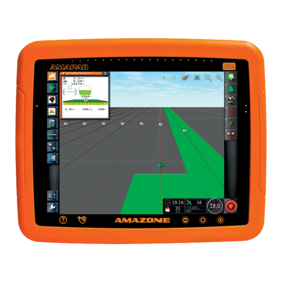
- Page 1 Operating instructions MG5574-EN-II | B.1 | 25.10.2016 Control terminal AMAPAD Original operating instructions...
-
Page 3: Table Of Contents
Your opinion is important Entering the user settings B Assembly instructions 2.1 Entering the region settings 2.2 Configuring the lightbar C AMAPAD at a glance 2.3 Configuring the environment 2.4 Configuring the map Connections and buttons 2.5 Changing the user access level Basic buttons and LEDs 2.6 Defining the user controls... - Page 4 | TABLE OF CONTENTS | 5.4 ECU configuration 11 Editing job data 5.5 Geometry 12 Calling up job information 5.6 Configuring the part-width section 13 Define working time control 5.7 Configuring ISOBUS J Managing fields 5.8 Configuring audio signals 5.9 Configuring the GPS speed simulation Creating a new field G Using the operating menu Creating a boundary line...
- Page 5 Managing AUX-N functions Calling up the system diagnosis O Using automatic reverse drive Determining the software version detection LED display Contact to AMAZONE P Using part-width section control Indexes Using manual part-width section control GLOSSARY Using automatic part-width section control INDEX 2.1 Configuring the control mode...
-
Page 6: A About This Operating Manual
A | About this operating manual | About this operating manual 047206 Meaning of the operating manual 020879 The operating manual is an important document and a part of the electronic product. 1. Before starting work, read and observe the respective sections of the operating manual. -
Page 7: Diagrams
A | About this operating manual | Diagrams Diagrams 021149 4.1 Notes 021152 NOTE Indicates practical tips and instructions that will help you to make optimal use of all the functions of your implement. 4.2 Instructions 021150 Numbered instructions 021156 Actions that have to be performed in a chronological sequence are represented as numbered instructions. -
Page 8: Lists
A | About this operating manual | Diagrams Instructions without sequence 021155 Instructions that do not require a specific sequence are shown as a list with tilted arrows. Action Action Action 4.3 Lists 007273 Lists are used, for example, to show different selection options. -
Page 9: Your Opinion Is Important
Please send us your suggestions by post, fax or email: AMAZONEN-WERKE H. DREYER GmbH & Co. KG P.O. Box 51 D-49202 Hasbergen Fax: +49 (0) 5405 501-234 Email: td@amazone.de MG5574-EN-II | B.1 | 25.10.2016... -
Page 10: B Assembly Instructions
B | Assembly instructions | Assembly instructions 007261 MG5574-EN-II | B.1 | 25.10.2016... -
Page 11: C Amapad At A Glance
C | AMAPAD at a glance | AMAPAD at a glance 007210 Connections and buttons 001280 USB port, on the side of the AMAPAD Speakers On/Off button Reset button USB port Serial port 2, by default for the GPS output... -
Page 12: D Basic Operation
007211 Switching on the AMAPAD 005233 Press and hold the green On/Off button 1 on the back of the AMAPAD until the light bar lights up. The AMAPAD is started. Changing the language 002288 The language for the warning message and the user interface can be changed directly after starting the AMAPAD. -
Page 13: Switching Off The Amapad
D | Basic operation | Switching off the AMAPAD A confirmation for restarting is shown. 4. Confirm restart with Confirming the terms of use 002291 After the AMAPAD has been started, a warning message containing the terms of use appears. The terms of use must be confirmed before the AMAPAD can be used. -
Page 14: Resetting The Amapad
Resetting the AMAPAD 001290 NOTE When the AMAPAD is reset, all data that is not saved will be lost. Only reset the AMAPAD if it crashed or cannot be switched off normally. Press the red Reset button 1 on the back of the AMAPAD. -
Page 15: Using The Basic Buttons
D | Basic operation | Using the basic buttons During operation, do not rest your hand on the touchscreen, otherwise the AMAPAD will not react. Using the basic buttons 005512 Help Removing the USB flash drive safely Multi-function button Brightness... -
Page 16: Switching Between The Main Menus
Automatic: Brightness is automatically adjusted to the light conditions. Switch through the modes with until the desired mode is set. Switching between the main menus 005511 The user interface on the AMAPAD consists of 2 main menus. MG5574-EN-II | B.1 | 25.10.2016... - Page 17 D | Basic operation | Switching between the main menus Switching to the setup menu 005672 In the operating menu, switch to the setup menu with Switching to the operating menu 005671 In the setup menu, switch to the operating menu with MG5574-EN-II | B.1 | 25.10.2016...
-
Page 18: E User Interface At A Glance
E | User interface at a glance | User interface at a glance 007212 General warning messages 002299 Warning messages are issued for different events. The functions of a warning message will be explained in the following. For a detailed description of the different warning messages, see page 222. -
Page 19: General Control Elements
Warning messages that are issued by the implement. Switch to the Universal Terminal. Close the warning message. Warning message for AMAZONE implements is acknowledged in the ECU. Acknowledge the warning message. Warning message is acknowledged in the ECU. General control elements 001360 3.1 Selection list... -
Page 20: Assistant
E | User interface at a glance | General control elements Confirm entries with Cancel entries with Increase numerical value with Decrease numerical value with 3.3 Assistant 002383 Assistants guide the user through complex system settings. The system settings are divided into individual work steps. -
Page 21: Buttons In The Operating Menu
E | User interface at a glance | Buttons in the operating menu Name of the system setting Back Work step Progress in percent Button for the entry Continue Buttons in the operating menu 009793 4.1 Buttons in the job menu 009812 More More... -
Page 22: Buttons In The Field Menu
E | User interface at a glance | Buttons in the operating menu 4.2 Buttons in the field menu 009813 More More Button Function Button Function information information Configure the Create a new see page 127 boundary see page 129 field offset Setting flag... -
Page 23: Buttons In The Steering Options Menu
E | User interface at a glance | Buttons in the operating menu More More Button Function Button Function information information Activate Interrupt adaptive recording of see page 147 see page 150 curved track the curved line track line Set starting Load track line see page 154 point for AB... -
Page 24: Buttons In The Map View
E | User interface at a glance | Buttons in the operating menu 4.7 Buttons in the map view 047207 More More Button Function Button Function information information Indicates whether the Change see page see page 104 selection mode perspective is enabled Focus on Enlarge or... -
Page 25: Other Buttons
E | User interface at a glance | Buttons in the operating menu 4.10 Other buttons 060590 More Button Function Button Function information Switch Switch automatic part- automatic width section see page 186 see page 166 steering on or control on or Use global Change track see page 219... -
Page 26: Configuring The Amapad
F | Configuring the AMAPAD | Configuring the AMAPAD 005570 Using the setup menu 001289 MG5574-EN-II | B.1 | 25.10.2016... -
Page 27: Entering The User Settings
F | Configuring the AMAPAD | Entering the user settings First menu level Previous menu Second menu level Next menu Third menu level Selected menu Last menu level Exit the setup menu Enter settings In these operating instructions, the paths to the settings are displayed as shown opposite. - Page 28 F | Configuring the AMAPAD | Entering the user settings 4. Confirm with 5. Exit the setup menu with 6. Confirm restart with Defining the format for the decimal separator 001253 1. In the setup menu, tap on "User" > "Region" >...
- Page 29 F | Configuring the AMAPAD | Entering the user settings NOTE The current data cannot be set manually. The date is only available if there is a GPS signal. Changing the time format 005329 The date specification is used for the job data and for created files.
-
Page 30: Configuring The Lightbar
F | Configuring the AMAPAD | Entering the user settings 2.1.3 Defining the regional units 005288 Defining the system of units 005287 1. In the setup menu, tap on "User" > "Region" > "Units". 2. Tap on "Measuring units". 3. Select the system of units. - Page 31 F | Configuring the AMAPAD | Entering the user settings 1. In the setup menu, tap on "User" > "Lightbar". 2. Tap on "Lightbar". 3. Select "Enabled". NOTE The lightbar only works if there is a GPS signal. The lit blue LED in the middle of the lightbar indicates that the lightbar is ready for operation.
- Page 32 F | Configuring the AMAPAD | Entering the user settings 1. In the setup menu, tap on "User" > "Lightbar". 2. Tap on "LED spacing". Setting range: 0.001 m to 2 m 3. Enter the distance. 4. Confirm with Defining the LED mode...
-
Page 33: Configuring The Environment
F | Configuring the AMAPAD | Entering the user settings 1. In the setup menu, tap on "User" > "Lightbar". 2. Tap on "LED mode". 3. Select mode. 4. Confirm with 2.3 Configuring the environment 005340 Adjusting the volume 005339... - Page 34 F | Configuring the AMAPAD | Entering the user settings Setting the button tones 005343 1. In the setup menu, tap on "User" > "Environment". 2. Tap on "Button clicks". 3. Enable the function disable. Setting the audio alarm 005338 The AMAPAD can issue various alarms.
- Page 35 F | Configuring the AMAPAD | Entering the user settings Recalibrating the touchscreen 001449 NOTE This function is only available for AMAPADs with the model number NI129. The model number is written on the rear side of the AMAPAD 1 .
- Page 36 F | Configuring the AMAPAD | Entering the user settings 10. Terminate the calibration with "Close". The AMAPAD will be rebooted. Touchscreen sensitivity 001452 NOTE This function is only available for AMAPADs with the model number NI129. The model number is written on the rear side of the AMAPAD 1 .
- Page 37 F | Configuring the AMAPAD | Entering the user settings Configuring the multi-function button 005538 Here, the function of the multi-function button 1 can be defined. 1. In the setup menu, tap on "User" > "Environment". 2. Tap on "Multi-function button mode".
- Page 38 F | Configuring the AMAPAD | Entering the user settings 1. In the setup menu, tap on "User" > "Environment". 2. Tap on " Global start screen mode". Possible settings: Select: The multi-function button is used to open the "...
- Page 39 F | Configuring the AMAPAD | Entering the user settings 2. Tap on " Automatic steering status window ". Possible settings: Disabled: The window for the steering status can only be called up through the job menu. Opens automatically: If the automatic steering cannot be started, the window for the steering status will be shown.
-
Page 40: Configuring The Map
F | Configuring the AMAPAD | Entering the user settings 2.4 Configuring the map 005350 Defining the point of focus 005337 With the point of focus, you can define whether the vehicle symbol or the implement symbol should be centred on the map. - Page 41 F | Configuring the AMAPAD | Entering the user settings Map focus auto-shift 005344 When miniature views are opened in the operating menu, the vehicle symbol can be covered by the miniature views on the map. With the map focus, you can define whether the map should be automatically shifted when miniature views are opened.
- Page 42 F | Configuring the AMAPAD | Entering the user settings Pausing boundary recording with master 005352 Manual boundary line recording can be interrupted during application by switching off all of the part-width sections. This has the advantage that the boundary line recording does not have to be interrupted separately when manoeuvring on the field.
-
Page 43: Changing The User Access Level
F | Configuring the AMAPAD | Entering the user settings 2.5 Changing the user access level 005351 To disable certain menus on the AMAPAD user interface, the different user access levels can be enabled with the access levels. 1. In the setup menu, tap on "User" > "Access level". -
Page 44: Entering The System Settings
F | Configuring the AMAPAD | Entering the system settings 1. Select "Setup menu" > "User" > "User controls". To enable or disable the menus for the individual user access levels, select the buttons in the corresponding column. To see a preview of the configured user interface, select "Preview"... - Page 45 F | Configuring the AMAPAD | Entering the system settings NOTE A license and additional hardware must be purchased for this function. For more information, see page 227. Enabling the wireless network 005397 A wireless network connection for remote assistance can be set up with the AMAPAD.
- Page 46 F | Configuring the AMAPAD | Entering the system settings 3.1.2 Configuring the track guidance system functions 005370 Enabling automatic steering 005387 This function enables or disables the automatic steering system. NOTE This function is only available if one of the following GPS receivers has been selected, see page 52.
- Page 47 F | Configuring the AMAPAD | Entering the system settings 1. In the setup menu, tap on "System" > "Functions" > "Track guidance". 2. Tap on " Reverse detection". Possible settings: Enabled: Reverse driving of the vehicle is automatically detected and the vehicle symbol moves backwards on the map.
- Page 48 F | Configuring the AMAPAD | Entering the system settings Job assistant: the menu point "Job assistant" is added in the job menu. For more information, see page 113. Quick start: In the "Functions" menu and in the job menu, the menu item "Quick start" will be added.
- Page 49 F | Configuring the AMAPAD | Entering the system settings Locking the setup menu 007624 When this function is enabled, access to the setup menu is locked as long as a job is started. 1. Select "Setup menu" > "System" > "Functions" >...
- Page 50 F | Configuring the AMAPAD | Entering the system settings 2. Tap on the desired options in the list. 3. Enable the options under "Option status". For some of the options, other settings can be entered. In these cases, additional buttons are shown under the "Option status"...
- Page 51 F | Configuring the AMAPAD | Entering the system settings Options Working procedures Additional settings Prerequisites "Create name for field": "Standard": The new field is given the date and the time of creation as a name. "User-defined": Another Opens the menu where a setting will be shown.
- Page 52 F | Configuring the AMAPAD | Entering the system settings Options Working procedures Additional settings Prerequisites "Measure": Select track line: The menu for selecting a track line will be opened Create track line: The menu for creating a track line will be opened "Create name for track...
-
Page 53: Configuring The Gps
F | Configuring the AMAPAD | Entering the system settings Under "Measures", the following settings are possible: "Select job": The menu for selecting a job will be opened. "No job": The current job will be deleted. Possible to work without a job. - Page 54 F | Configuring the AMAPAD | Entering the system settings 3.2.1 Configuring the receiver 005369 Selecting the GPS receiver 005388 The AMAPAD can process GPS signals from an external receiver. To do so, the connected GPS receiver must be selected.
- Page 55 F | Configuring the AMAPAD | Entering the system settings NOTE Firmware upgrades can only be performed on the following GPS receivers: SGR-1 AGI-3 AGI-4 1. In the setup menu, tap on "System" > "GPS" > "Receiver". 2. Tap on "Firmware upgrade".
- Page 56 F | Configuring the AMAPAD | Entering the system settings Possible settings: Enabled: When the vehicle is switched off, the GPS receiver power supply comes from the vehicle battery. Disabled: When the vehicle is switched off, the GPS receiver power supply is interrupted.
- Page 57 F | Configuring the AMAPAD | Entering the system settings 1. In the setup menu, tap on "System" > "GPS" > "Receiver". 2. Tap on "Load OAF file". 3. Follow the instructions on the screen. Set the baud rate 005371 The baud rate refers to the transmission speed of the GPS receiver.
- Page 58 F | Configuring the AMAPAD | Entering the system settings Selecting correction source 005392 Correction signals increase the precision of the GPS signal. 1. In the setup menu, tap on "System" > "GPS" > "Correction". 2. Tap on "Correction source".
- Page 59 F | Configuring the AMAPAD | Entering the system settings NOTE When GLONASS is enabled, signals from GPS satellites are no longer received, even if sufficient GPS satellites are available again. GLONASS can be enabled for the following correction sources...
-
Page 60: Configuring The Serial Ports
When the GPS signal is too imprecise, the automatic steering system cannot be started. The fallback system allows the AMAPAD to fall back on the GPS signal with the next lowest precision to still be able to start the automatic steering. - Page 61 F | Configuring the AMAPAD | Entering the system settings 1. In the setup menu, tap on "System" > "GPS" > "Output". 2. Select "GPS receiver COM". 3. Select the COM port. NOTE Setting for supplied AMAZONE wiring harness: Defining the COM port for the GPS output 005376 Selection of the COM port for the GPS output.
-
Page 62: Configuring The Alarms
F | Configuring the AMAPAD | Entering the system settings 3.4 Configuring the alarms 005384 3.4.1 Configuring general alarms 001881 1. In the setup menu, tap on "System" > "Alarms". 2. Select the alarm from the alarm list. 3. Tap on "Alarm state". - Page 63 F | Configuring the AMAPAD | Entering the system settings Configuring the end of row alarm 005373 When the vehicle approaches the boundary line, an alarm can be issued at a certain distance from the boundary. 1. In the setup menu, tap on "System" > "Alarms".
-
Page 64: Configuring The Flag Points
F | Configuring the AMAPAD | Entering the system settings 9. Tap on " Look ahead distance ". 10. Enter the additional distance from the first and second distances at which the alarm should be triggered. 3.5 Configuring the flag points... -
Page 65: Configuring The Isobus
F | Configuring the AMAPAD | Entering the system settings 3.6 Configuring the ISOBUS 005378 3.6.1 Configuring the Universal Terminal 009192 REQUIREMENTS User access level has been set to "Standard" or "Expert"; see page 41 Enabling the Universal Terminal 005380 1. - Page 66 F | Configuring the AMAPAD | Entering the system settings 1. In the setup menu, tap on "System" > "ISOBUS"> "UT". 2. Tap on "UT number". Possible settings: Number between 1 and 32 Defining the soft keys per column 005386 Setting for how many soft keys are displayed in each column on the Universal Terminal.
- Page 67 F | Configuring the AMAPAD | Entering the system settings 3. Select the location. NOTE Recommended setting: On the right (two columns) Defining the location of the working set key 005377 With this setting, the location of the working set key on the Universal Terminal is defined.
- Page 68 F | Configuring the AMAPAD | Entering the system settings NOTE The AMAPAD normally automatically detects the TC version. To define the TC version, the following applies: AMAZONE implements: TC version 3 For Peer Control: TC version 4 1. Select "Setup menu" > "System" > "ISOBUS" >...
- Page 69 F | Configuring the AMAPAD | Entering the system settings 1. Select "Setup menu" > "System" > "ISOBUS" > "TC". 2. Tap on "Manual control mode for part-width section control". Possible settings: ECU-controlled: if automatic part-width section control is disabled, the part-width sections can no longer be controlled using the virtual part-width section switch.
- Page 70 F | Configuring the AMAPAD | Entering the system settings Quick access in the miniature view Function button for quick access Button for opening the miniature views 1. Select "Setup menu" > "System" > "ISOBUS" > "AUX". Select "Setup menu" > "System" > "ISOBUS".
- Page 71 F | Configuring the AMAPAD | Entering the system settings NOTE If the number of miniature views for AUX input is changed, the function assignments will be lost. All the the functions must then be reassigned. 6. Define the number.
-
Page 72: Using Aids
F | Configuring the AMAPAD | Entering the system settings Enabling terminal functions for AUX-N input 048270 The AMAPAD functions can be controlled using the quick access in the miniature view or through an external input device. To do this, the functions must be enabled for AUX-N input. -
Page 73: Configuring A Vehicle
F | Configuring the AMAPAD | Configuring a vehicle Configuring a vehicle 005558 4.1 Creating a new vehicle 001490 In the "Vehicle" menu, the vehicles on which the AMAPAD will be used are configured. Vehicles can be selected from the database on the AMAPAD. If the desired vehicle is not available in the database, a custom vehicle can be created. - Page 74 F | Configuring the AMAPAD | Configuring a vehicle NOTE For the AMAZONE Pantera self-propelled sprayer, the implement must be configured at this point; see page 85, " Create new implement ", Step 7. 4.1.2 Creating a custom vehicle 001492 1.
- Page 75 F | Configuring the AMAPAD | Configuring a vehicle 4.1.3 Defining the vehicle geometry 001493 NOTE The vehicle geometry is required for precise functioning of the track guidance system. Measure the vehicle precisely. The tolerance is of 5 cm. NOTE The adjustable geometry values depend on the vehicle selection.
- Page 76 F | Configuring the AMAPAD | Configuring a vehicle Geometry Geometry Description Figure Description Figure value value Distance from the centre of Distance from Axle distance the front axle Axle height the axle to the to the centre of ground.
-
Page 77: Selecting A Vehicle
F | Configuring the AMAPAD | Configuring a vehicle Geometry Geometry Description Figure Description Figure value value Only for caterpillar Only for tractors. articulated Distance vehicles. between the Distance Track spacing left edge of the Pivot point between the left caterpillar... - Page 78 F | Configuring the AMAPAD | Configuring a vehicle 2. Select a vehicle from the list. 3. Confirm selection with A restart must be performed for some vehicles. 4. Confirm restart with The "Vehicle geometry" menu will be shown. To change the vehicle geometry, see page 75.
-
Page 79: Adding Vehicle Geometry Data To The Job Data
F | Configuring the AMAPAD | Configuring a vehicle 4.2.2 Copying vehicle data 001556 Vehicle data can be copied to create vehicles that only differ slightly. 1. In the setup menu, tap on "Vehicle" > "Select". 2. Select a vehicle from the list. -
Page 80: Configuring The Steering Controller
F | Configuring the AMAPAD | Configuring a vehicle 2. Select 3. Confirm with 4.4 Configuring the steering controller 005402 NOTE This menu is only available if the automatic steering is enabled; see page 44. NOTE The steering control settings are not assigned to the selected vehicle. - Page 81 F | Configuring the AMAPAD | Configuring a vehicle NOTE The " Auto detect " setting does not revoke the selection of the proper steering controller. Selecting the CAN bus 005405 The steering control can take place through different CAN buses.
-
Page 82: Antenna Configuration
F | Configuring the AMAPAD | Configuring a vehicle Possible settings: Virtual: Automatic steering can only be switched on using the button the in operating menu. Virtual and external console input: Automatic steering can be switched on using the button in the operating menu and using an external switch. - Page 83 F | Configuring the AMAPAD | Configuring a vehicle 2. Tap on "Antenna type". Possible settings: Integrated: The GPS antenna is integrated in the GPS receiver. External: The GPS receiver is equipped with an external GPS antenna. This setting requires additional specifications on the position of the GPS antenna.
-
Page 84: Configuring An Implement
When the AMAPAD is started, the implement detection assistant is shown in the operating menu. NOTE The AMAPAD requires up to 2 minutes to detect the implement. REQUIREMENTS Implement is properly connected; see page 8 MG5574-EN-II | B.1 | 25.10.2016... - Page 85 F | Configuring the AMAPAD | Configuring an implement If a profile should be created for the implement, confirm with "Yes". NOTE Other options: "No": An implement profile will not be created. The AMAPAD saves this selection and no longer opens the assistant for this implement.
- Page 86 F | Configuring the AMAPAD | Configuring an implement If the implement type "Self-propelled" was selected, select a vehicle type from the list. 4. Continue with If the name for the implement should be changed, select "Profile name" and enter the name.
-
Page 87: Creating A New Work Implement
F | Configuring the AMAPAD | Configuring an implement 7. Confirm with NOTE Please observe the instructions on the display. If the implement should be loaded, confirm with 5.2 Creating a new work implement 001581 NOTE This operating manual only describes implements with ISOBUS. -
Page 88: Selecting The Implement
F | Configuring the AMAPAD | Configuring an implement 3. Confirm restart with 4. Tap on "Implement name". NOTE Sensible implement names should be assigned to make it easier to manage the implements. 5. Enter the name. 6. Confirm the entry with The implement setup assistant will be shown. - Page 89 F | Configuring the AMAPAD | Configuring an implement 3. Confirm selection with A restart must be performed for some implements. 4. Confirm restart with 5.3.1 Importing implement data 001573 Implement data can be saved to a USB stick and imported onto the AMAPAD.
-
Page 90: Ecu Configuration
F | Configuring the AMAPAD | Configuring an implement 2. Select implement from the list. 3. Confirm selection with A restart must be performed for some implements. 4. Confirm restart with 5. Select 6. Select the "Implement name". 7. Enter an implement name for the copy. -
Page 91: Geometry
F | Configuring the AMAPAD | Configuring an implement Selecting the implement function 005418 1. In the setup menu, tap on "Implement" > "ECU". 2. Tap on "Implement function". Possible settings: Sprayer Spreader Precision airplanter Refreshing the ECU settings 005412 The geometry data can be transmitted from the ECU of the selected implement to the AMAPAD. -
Page 92: Configuring The Part-Width Section Control
F | Configuring the AMAPAD | Configuring an implement NOTE Except for the Overlap, the setting of the geometry values for ISOBUS implements is performed only through the Universal Terminal. 5.5.1 Overlap, setting 004995 Overlap can be used to influence the track line spacing for track guidance. - Page 93 F | Configuring the AMAPAD | Configuring an implement NOTE For ISOBUS implements, the configuration of the part- width sections is performed only through the Universal Terminal. For information on the configuration of part-width sections for non-ISOBUS implements, see page 227.
- Page 94 F | Configuring the AMAPAD | Configuring an implement NOTE A maximum of 16 section switches can be activated. 7. In the "Switch" table, assign each section to a switch. NOTE Multiple part-width sections can be actuated with the same section switch. To do so, the part-width sections must be assigned to the same section switch.
- Page 95 F | Configuring the AMAPAD | Configuring an implement For information on the configuration of part-width sections for non-ISOBUS implements, see page 227. Configuring the tact 005430 In this menu, the on/off point delays for switching the individual part-width sections are set. The part-width sections can also all be set together to the same on/off point delay on the "All"...
-
Page 96: Configuring Isobus
F | Configuring the AMAPAD | Configuring an implement 7. In the "Switch" table, assign each section to a switch. NOTE Multiple part-width sections can be actuated with the same section switch. To do so, the part-width sections must be assigned to the same section switch. -
Page 97: Configuring Audio Signals
3. Enable the audio signal disable. 5.9 Configuring the GPS speed simulation 005427 In this menu, it can be defined that the AMAPAD should determine the speed using the GPS signal, and like the AMAPAD, transmit the speed to the implement. NOTE... - Page 98 F | Configuring the AMAPAD | Configuring an implement Enabling ISO ground speed 005419 When this function is enabled, the speed is transmitted to the implement through the ISOBUS protocol. NOTE The ISO forward speed can be used if the tractor does not send a speed.
- Page 99 F | Configuring the AMAPAD | Configuring an implement disable. MG5574-EN-II | B.1 | 25.10.2016...
-
Page 100: G Using The Operating Menu
Function menu Job menu Miniature view Automatic reverse detection or automatic Map view steering Dashboard All of the AMAPAD's functions can be controlled using the operating menu. Access to the implement controls with the Universal Terminal MG5574-EN-II | B.1 | 25.10.2016... -
Page 101: Using The Function Menu
Automatic steering Using the function menu 001359 The function menu is used to call up information and to control the various functions of the AMAPAD and the connected implement. NOTE Different buttons can be shown in the function menu, depending on the connected implement and the settings in the setup menu. -
Page 102: Opening A Miniature View
G | Using the operating menu | Using the function menu 1.1 Opening a miniature view 002348 Open the miniature views with the buttons in the function menu. 1.2 Maximising the miniature view 002352 NOTE Not all miniature views can be maximised. Miniature views that can be maximised have this button at the top right corner: NOTE... -
Page 103: Using The Tabs In The Miniature View
G | Using the operating menu | Using the function menu 1.3 Using the tabs in the miniature view 002418 Several miniature views contain tabs that can be individually opened. Open the tabs with the buttons 1 . 1.4 Closing a miniature view 002351 To close the miniature view, there are 3 options: Tap again on the button for the opened miniature... -
Page 104: Using The Map View
G | Using the operating menu | Using the map view Using the map view 002422 Miniature view of the map view Confirm selection Configure coverage map 10 Vehicle focus Vehicle symbol 11 Configure map layers Implement symbol 12 changing the perspective Exclusion area (dark grey) 13 Reduce map section Worked area (coverage), (green) -
Page 105: Calling Up The Map View
G | Using the operating menu | Using the map view A boundary line can be created to define the field size and use automatic part-width section control. The boundary line is marked on the map with a blue line. Exclusion areas within a field where the application should be stopped can be marked with a boundary line. -
Page 106: Changing The Perspective
G | Using the operating menu | Using the map view 2.3 changing the perspective 002421 3 perspectives are available. The button changes depending on the set perspective. Button Description The upper edge of the map remains oriented to the north. -
Page 107: Selecting Map Layers
The selected elements will be shown on the map. Configuring the dashboard 001382 NOTE The following figures show all of the available elements for the dashboard. When the AMAPAD is started for the first time, not all of the elements are enabled. MG5574-EN-II | B.1 | 25.10.2016... -
Page 108: Adding Data Fields
G | Using the operating menu | Configuring the dashboard Data fields on the dashboard Implement data. The displayed data varies Speed depending on the connected implement. Direction of travel Date and time Track deviation and worked area GPRS signal strength and WLAN signal strength Track number and remaining area GPS data GPS data on the dashboard... - Page 109 G | Using the operating menu | Configuring the dashboard 1. Tap on any data field on the dashboard. The selection list for the data fields will be opened. 2. Select the desired data fields 3. Confirm with MG5574-EN-II | B.1 | 25.10.2016...
-
Page 110: Editing Data Fields
G | Using the operating menu | Configuring the dashboard 3.2 Editing data fields 048221 1. Tap on any data field on the dashboard. The selection list for the data fields will be opened. To edit an existing data field on the dashboard, tap on the desired data field on the dashboard. - Page 111 G | Using the operating menu | Configuring the dashboard 3. Choose the desired data for the selected data field. 4. Confirm with MG5574-EN-II | B.1 | 25.10.2016...
-
Page 112: H Working Without A Job
H | Working without a job | Working without a job 048471 If the job data should not be recorded, work can be performed without using a job. To do so, the "Quick start" function is used to automatically create a job, and delete it again when the function is called up again. -
Page 113: Calling Up The Quick Start
H | Working without a job | Calling up the quick start 6. In the "Options" list, select the option "Change job". 7. Enable the option with "Option status". 8. Under "Measures", select "No job". 9. Enable the "Hide on success" option 10. -
Page 114: I Managing Jobs
I | Managing jobs | Managing jobs 005520 Jobs are managed through the job menu. The job menu can be found in the map view. In the job menu, the following functions can be executed: Quick start: Enabling quick start functions; see page 47 Field menu: Managing fields;... -
Page 115: Using The Job Menu
I | Managing jobs | Using the job menu Using the job menu 001364 1. Tap on one of the buttons in the job menu 1 . The menu bar will be opened. 2. Tap on one of the buttons in the menu bar 2 . Another menu bar 3 will be opened or a menu will be opened. -
Page 116: Using The Quick Start
I | Managing jobs | Using the quick start REQUIREMENTS The job assistant is enabled; see page 45 1. Select in the job menu. The job assistant will be shown. 2. Select the desired menu in the job menu. The job assistant shown the information on the selected menu. -
Page 117: Starting A Job
I | Managing jobs | Starting a job To edit master data, select To add new master data, select To delete master data, select Starting a job 005562 When starting a job, the application will be started and the job data will be recorded. REQUIREMENTS GPS receiver is connected GPS is configured;... -
Page 118: Creating A New Job
I | Managing jobs | Creating a new job TROUBLESHOOTING The job cannot be started? The conditions for starting the job have not be fulfilled. The "Start job status" window will be shown. A red status display means that these conditions have not been fulfilled. - Page 119 I | Managing jobs | Creating a new job The job total values include the following data: Distance in working position Time in working position Worked area Applied quantity REQUIREMENTS When boundary lines or tracks lines should be created, a field must be created; see page 1.
-
Page 120: Importing Job Data
NOTE When the job data is imported, the existing jobs on the AMAPAD will be deleted. To keep the existing jobs, they must be exported; see page 119. 1. Insert the USB stick with the "TASKDATA.XML" file into the AMAPAD. -
Page 121: Exporting Task Data
6. Select the desired "TASKDATA.XML" file. 7. Under "Import mode", select whether all of the data or only master data should be imported. 8. Confirm selection with If job data is on the AMAPAD: confirm overwriting. The job data will be imported. Exporting task data... - Page 122 Field data Master data When job data is exported, it will be deleted on the AMAPAD. The inventory data and master data will be copied. A job data backup will be created in the inventory manager. If the job data have been lost, see page 216.
-
Page 123: Selecting A Job
I | Managing jobs | Selecting a job If other data formats are required, select the additional data formats. 7. Confirm with The job data will be exported. Selecting a job 001950 This menu can be used to select created or imported jobs to start them. -
Page 124: Filtering Jobs
I | Managing jobs | Selecting a job 9.1 Filtering jobs 048464 The jobs can be filtered according to the master data. To do so, filters are added in the "Select jobs" menu. These filters can be individually edited. 1. Tap on "Filter". 2. -
Page 125: Deleting A Job
I | Managing jobs | Deleting a job 1. Tap on "Sorting". 2. Select the sorting method. 3. Confirm selection with The existing jobs will be sorted. Deleting a job 005534 The worked area and the recorded total values for the current job can be deleted. -
Page 126: Editing Job Data
I | Managing jobs | Editing job data Editing job data 060592 The job data manager is used to manage job data and master data. REQUIREMENTS "Manage job data" is enabled in the user controls; see page 41 1. Select in the function menu. -
Page 127: Define Working Time
I | Managing jobs | Define working time Job settings Job statistics Job total values Track guidance Job state: Job started: Job stopped: To obtain a general overview, enlarge the miniature view. Define working time 001964 During the execution of a job, detailed information can be entered about the work. - Page 128 I | Managing jobs | Define working time 3. Select the work to be performed. 4. Start the job. The working time will be documented. NOTE The default setting for the type of work is "Effective". When the job is interrupted, the type of work will be set back to the default setting.
-
Page 129: J Managing Fields
J | Managing fields | Managing fields 005518 Overview of the field menu New field: Opens the "Create new field" menu. Flag point: Opens the "Add marker" menu. Boundary line recording: Starts or interrupts the recording of the boundary line. When the boundary line recording has been started, the symbol on the button changes to Complete boundary line recording: Terminates the... - Page 130 J | Managing fields | Creating a new field 1. In the job menu, tap on 2. Call up the "New field" menu with 3. Enter a name for the field under "Name". NOTE Enter a sensible name to make it easier to manage the fields later.
-
Page 131: Creating A Boundary Line
3 . Using the recorded boundary line, the AMAPAD calculates the size of the marked area. When the area has been defined as a work area, the AMAPAD can calculate the size of the worked areas and remaining areas. When a boundary line has been... - Page 132 J | Managing fields | Creating a boundary line Boundary offset Edge of the boundary area Boundary line on the AMAPAD NOTE The boundary offset serves to precisely record the boundary line. Determine the exact boundary offset. 1. In the job menu, tap on 2.
- Page 133 J | Managing fields | Creating a boundary line 6. Confirm entries with 2.1.2 Starting the boundary line recording 009136 REQUIREMENTS Field is created; see page 127 Job is created and the field is added to the job; see page 116 Implement is selected;...
-
Page 134: Interrupting The Boundary Line Recording
Boundary lines that were previously created in a Farm Management Information System can be loaded as a shape file. The shape files can be imported to the AMAPAD using a USB stick. REQUIREMENTS Field is created; see page 127 Job is created and the field is added to the job;... -
Page 135: Creating The Boundary Line From The Coverage
2.4 Creating the boundary line from the coverage 007614 The AMAPAD can draw a boundary line around a worked area. This makes it possible e.g. to edit the edge MG5574-EN-II | B.1 | 25.10.2016... - Page 136 J | Managing fields | Creating a boundary line of a field and to create the boundary line from the worked area. In additional to boundary lines for fields, boundary lines can be created for exclusion areas. REQUIREMENTS All boundary line saved with this field have been deleted;...
-
Page 137: Editing The Boundary Line
J | Managing fields | Editing the boundary line The "Exclusion areas" button turns green. 7. With the "Minimum exclusion area" setting, the minimum size for exclusion areas is defined. 8. Confirm the settings with The boundary lines will be created according to the settings. - Page 138 J | Managing fields | Editing the boundary line The selection confirmation 1 will be coloured after half a second. 2. Move your finger on a boundary line until the boundary line information 2 is shown. 3. Take your finger off the map. 4.
-
Page 139: Configuring The Headlands
The headland describes the area within the boundary line in which the vehicle is turned. The headland boundary is marked with an orange-coloured line on the AMAPAD. NOTE The automatic part-width section control can be configured such that the sections are switched off inside the headlands;... -
Page 140: Configuring Headland Actions
138. 8. Confirm the settings with 4.1 Configuring headland actions 005677 The AMAPAD can perform 2 headland actions when the vehicle approaches the headlands: Issue an alarm Enlarge the map MG5574-EN-II | B.1 | 25.10.2016... - Page 141 J | Managing fields | Configuring the headlands In the "Headland options" menu, tap on "Configure actions". Configuring the alarm 005675 1. Under "Action name", select "Alarm". 2. Under "Action state", enable the action. 3. Under "Message", enter a text for the alarm message.
-
Page 142: Deleting All Boundary Lines
J | Managing fields | Deleting all boundary lines Configuring Auto Zoom 005676 1. Under "Action name", select "Auto Zoom". 2. Under "Action state", enable the action. 3. Under "Zoom level", set the extent to which the automatic zoom should enlarge the map. 4. -
Page 143: Setting Flag Points For Hazards
J | Managing fields | Setting flag point NOTE Flag points can be adjusted in the setup menu, see page 62. 6.1 Setting flag points for hazards 001781 1. Drive to the hazard point. NOTE Flag points are always set at the position of the vehicle rear axle. - Page 144 J | Managing fields | Setting flag point NOTE Flag points are always set at the position of the vehicle rear axle. 2. In the job menu, tap on 3. Call up the " Add marker " menu with 4. Tap on "Custom". 5.
-
Page 145: Setting Flag Points For Gps Drift Correction
J | Managing fields | Setting flag point The flag point has been set. 6.2 Setting flag points for GPS drift correction 001788 With the GPS drift correction, deviations in the GPS signal can be corrected. A flag point can be used as a reference point in this case. -
Page 146: Editing Flag Points
J | Managing fields | Setting flag point 5. Select the desired symbol. 6. Tap on "Flag point name". NOTE Enter a sensible name to clearly identify the flag point as a reference point. 7. Enter the name. 8. Select the desired symbol. 9. - Page 147 J | Managing fields | Setting flag point Possible settings: "Change": Change the symbol for the flag point. "Rename": Rename the flag point. "Delete": Delete the flag point. "Clear all": Delete all of the flag points for the current job. "GPS drift correction": Perform GPS drift correction.
-
Page 148: Using Track Lines
K | Using track lines | Using track lines 005554 Track lines show the driver which track he needs to follow to work the field uniformly. Track lines are also required for automatic steering control. The spacing of the track lines corresponds to the set working width. NOTE The display of the track line menu differs depending on the set track pattern. -
Page 149: Creating Track Lines
K | Using track lines | Creating track lines Creating track lines 005521 1.1 Selecting the track line pattern 009809 NOTE Depending on the previously set track line pattern, the following symbols can be shown on the button for opening the track line menu: for straight A-B lines for circular track lines for curved track lines... -
Page 150: Creating A Straight A-B Line
K | Using track lines | Creating track lines 1.2 Creating a straight A-B line 001987 Straight A-B lines are suitable for fields that are mainly worked on straight tracks. REQUIREMENTS Field is created; see page 127 Track line pattern for A-B lines is selected; see page 147 NOTE Without a boundary line, only the middle track line and... - Page 151 K | Using track lines | Creating track lines 8. Drive to the end of the row. 9. Set the end point of the A-B line with The AMAPAD will automatically add the other track lines. 1.2.1 Creating the A-B line manually...
-
Page 152: Creating Curved Track Lines
K | Using track lines | Creating track lines Possible settings: Set start point: Defines the starting point of the A-B line using the current vehicle position. Latitude of the starting point for the A-B line. Longitude of the starting point for the A-B line. Set end point: Defines the end point of the A-B line using the current vehicle position. - Page 153 K | Using track lines | Creating track lines REQUIREMENTS Field is created; see page 127 Track line pattern for curved track lines is selected; see page 147 1. Select 2. Call up the "New track" menu with 3. Enter the track name. 4.
-
Page 154: Creating Circular Track Lines
K | Using track lines | Creating track lines NOTE Initially, only the recorded curved track line is shown. The corresponding curved track line will only be shown when the vehicle changes to the next row. 1.4 Creating circular track lines 002080 Circular track lines are suitable for special forms of management, where the fields are worked in a circular... -
Page 155: Creating Adaptive Track Lines
A scale is shown for the precision of the recorded circular track line. 7. Drive in circles around the centre of the field. When the AMAPAD has detected the radius of the circle, the circular track lines will be created. NOTE Only the middle circular track line and the circular track lines right and left of the vehicle are shown. -
Page 156: Re-Using Track Lines
K | Using track lines | Re-using track lines NOTE The adaptive curved track line will only be shown when the vehicle changes to the next row. Re-using track lines 002082 Created track lines can be re-used for different jobs. NOTE Adaptive curved track lines cannot be re-used. -
Page 157: Following Track Lines
Following track lines 005540 The AMAPAD has various displays to help the driver in following the created track lines with the vehicle. The driver can use these displays to check the track deviation. -
Page 158: Checking The Track Deviation With Lightbars
K | Using track lines | Following track lines 3.1 Checking the track deviation with lightbars 005541 The lightbar is located at the upper edge of the touchscreen 1 . During operation, the lightbar shows how far the vehicle has deviated from the defined track line. -
Page 159: Correcting The Track Lines
GPS drift. When the displayed track lines no longer match with the real tracks on the field, the displayed track lines can be manually shifted on the AMAPAD. To correct the track lines, see page 161. MG5574-EN-II | B.1 | 25.10.2016... -
Page 160: Correcting The Gps Reception
GPS drift is defined as the deviations of the GPS signal that result from the use of correction sources with low precision. GPS drift can be recognised when the vehicle symbol on the AMAPAD no longer corresponds to the actual position of the vehicle. MG5574-EN-II | B.1 | 25.10.2016... -
Page 161: Correcting The Gps Drift With The Gps Drift Options
The virtual reference point on the AMAPAD can be the boundary line, a flag point or the worked area. NOTE The GPS drift correction is not deleted when the AMAPAD is switched off. -
Page 162: Correcting The Gps Drift With A Flag Point
L | Correcting the GPS reception| Performing the GPS drift correction 3. Make corrections until the position of the vehicle symbol corresponds to the real position of the vehicle. 4. Confirm with 1.2 Correcting the GPS drift with a flag point 002175 REQUIREMENTS Flag point is set as a reference;... -
Page 163: Correcting The Track Lines
GPS drift. When the displayed track lines no longer match with the real tracks on the field, the displayed track lines can be manually shifted on the AMAPAD. 2.1 Entering the nudge offset 002137 The nudge offset describes the length by which the track lines should be shifted with each correction increment. -
Page 164: Shifting The Track Lines
When the track lines should be shifted to the right, tap on 3. Tap on the button until the track lines on the AMAPAD match with the real tracks on the field. 2.2.2 Shifting the track lines by a specified length 002154 1. -
Page 165: Shifting The Track Line To The Vehicle Position
L | Correcting the GPS reception| Saving the corrected track lines 3. Tap on "Total nudge". NOTE On the "Total nudge" button, the length by which the track lines were shifted is shown. Other shifts must be added or subtracted. When the track lines should be shifted to the right, enter a positive value. -
Page 166: Calling Up Gps Information
L | Correcting the GPS reception| Calling up GPS information 3. Tap on "Track line name". 4. Enter the name for the track line. 5. Confirm the entry with 6. Confirm with The corrected track lines will be saved and assigned to the current field. - Page 167 L | Correcting the GPS reception| Calling up GPS information GPS precision Number of satellites, call up satellite information Used correction signal Age of the correction signal in seconds Horizontal position deviation: Value smaller than 1: high precision, value greater than 4: low precision MG5574-EN-II | B.1 | 25.10.2016...
-
Page 168: M Using Automatic Steering
Opens the menu for steering calibration. Steering calibration 002200 Using the GPS data, the AMAPAD can control the steering of the vehicle and keep it on a created track line. The steering must be calibrated for the automatic steering to function properly. -
Page 169: Calibrating Compass
M | Using automatic steering| Steering calibration 1.1 Calibrating compass 002512 IMPORTANT Risk of implement damage! The required driving manoeuvre can cause damage to the coupled implement or the sprayer boom. Uncouple the implement and fold the sprayer boom before you begin with the compass calibration. -
Page 170: Calibrating Wheel Angle Sensor
M | Using automatic steering| Calling up the steering status 1.2 Calibrating wheel angle sensor 002513 NOTE The wheel angle sensor must not be calibrated for the AMAZONE Pantera self-propelled sprayer. For information on other vehicles, see page 227. 1.3 Calibrating alignment angle 002510 NOTE The calibration angle must only be calibrated if "RTK"... - Page 171 M | Using automatic steering| Calling up the steering status The "Steering status" will be opened. Steering status overview 002514 To be able to start automatic steering, certain conditions must be fulfilled. The steering status provides information on these conditions. The following table contains measures to fulfil the conditions.
-
Page 172: Coordinating The Automatic Steering
Check the connection to the GPS receiver. Track line synchronised Load the track line again and wait until the track line is synchronised. Prohibited operation Terminate all operations that are being executed on the AMAPAD. Operator presence Sit on the driver's seat. Steering wheel Let go of the steering wheel. - Page 173 M | Using automatic steering| Coordinating the automatic steering IMPORTANT Risk of implement damage! Because of the high setting values, the automatic steering reacts aggressively. This can cause damage to the coupled implement or the sprayer boom. Start by setting values for less aggressive steering reaction.
-
Page 174: Switching On The Automatic Steering
M | Using automatic steering| Switching on the automatic steering Switching on the automatic steering 005561 REQUIREMENTS Vehicle with automatic steering is configured, see page 71. Suitable GPS receiver is configured (AGI-3 or AGI-4), see page 51. Automatic steering is enabled, see page 79. Steering is calibrated, see page 166. -
Page 175: Switching Off The Automatic Steering
M | Using automatic steering| Switching off the automatic steering When the vehicle has reached the required speed, the automatic steering will be switched on. Switching off the automatic steering 002515 NOTE When all of the conditions for the steering status have not been fulfilled, the automatic steering will be switched off. -
Page 176: N Using The Universal Terminal
N | Using the Universal Terminal| Using the Universal Terminal 005527 MG5574-EN-II | B.1 | 25.10.2016... -
Page 177: Opening The Universal Terminal
002235 The Universal Terminal can be used to access the implement ECU. The user interface of the implement control is shown on the AMAPAD and can be operated there. The miniature view for the Universal Terminal can be found on function bar in the operating menu. -
Page 178: Enlarging The Section In The Miniature View
Using automatic AUX-N assignments 012253 When an implement or an external input device is connected to the AMAPAD, the implement or the external input device automatically sends an AUX-N assignment for specific functions to the AMAPAD. MG5574-EN-II | B.1 | 25.10.2016... - Page 179 It can take up to 2 minutes for the implement or the external input device to send the AUX-N assignments. When the AMAPAD has been started and an implement or external input device is connected, a message is shown with the provided AUX-N assignments.
-
Page 180: Managing Aux-N Functions
To delete all AUX-N assignments, tap on Managing AUX-N functions 007322 The functions of the AMAPAD and the connected implement can be executed using quick access buttons and using external input devices. For example, if an AmaPilot is connected, the functions can be assigned... - Page 181 N | Using the Universal Terminal| Managing AUX-N functions NOTE To be able to assign the AMAPAD functions, they must be enabled; see page 70. For a list of the AMAPAD functions: To filter the functions according to the implements,...
- Page 182 N | Using the Universal Terminal| Managing AUX-N functions 1. Press button on an external input device, e.g. the AmaPilot. The selected button will be assigned to the function. 2. Confirm assignments with Assignment for miniature view 007655 REQUIREMENTS Miniature view for AUX input enabled; see page 67 NOTE The miniature view for the AUX input is only...
- Page 183 N | Using the Universal Terminal| Managing AUX-N functions REQUIREMENTS Button on the dashboard for AUX input is enabled; see page 67 NOTE The button for the AUX input is only shown on the dashboard when an assignment is edited or assignments are already available.
- Page 184 N | Using the Universal Terminal| Managing AUX-N functions The "Select input device" menu will be opened. 2. Select the input device from the list. 3. Select the button or the key for the assignment Delete assignment with 4. Confirm assignments with Deleting an assignment 007338 To delete the assignment,...
-
Page 185: O Using Automatic Reverse Drive Detection
O | Using automatic reverse drive detection | Using automatic reverse drive detection 005245 The automatic reverse drive detection determines whether the vehicle is driving in reverse. When reverse driving is detected, the vehicle symbol also moves backwards on the map. Without automatic detection of reverse driving, the vehicle symbol turns around when driving in reverse. -
Page 186: P Using Part-Width Section Control
P | Using part-width section control| Using part-width section control 005528 Using manual part-width section control 005574 Virtual section switches can be enabled for sprayers and seed drills. The virtual section switches can be used to switch individual part-width sections on and off. The miniature view for manual part-width section control can be found on function bar in the operating menu. - Page 187 P | Using part-width section control| Using manual part-width section control Part-width section switch in the map view Part-width section numbers Status of the section switch: Green: Section switch is on, Red: Section switch is off Part-width section status: Red: Section is switched off, Yellow: Section is switched on and the application is stopped (generally by the automatic part-width section control).
-
Page 188: Using Automatic Part-Width Section Control
P | Using part-width section control| Using automatic part-width section control To switch the desired part-width section on or off: Tap on the corresponding section switch. Using automatic part-width section control 005565 With automatic part-width section control, the implement sections are automatically switched off when the implement crosses a specific boundary or a worked area. -
Page 189: Configuring The Control Mode
P | Using part-width section control| Using automatic part-width section control Possible settings: "Control mode": Control mode is used to configure the overlap of the part-width sections. "Boundary limit": The boundary limit is used to define the areas in which the part-width section are switched off. "ASC ON": This button is used to switch the automatic part-width section control on or off. - Page 190 P | Using part-width section control| Using automatic part-width section control Configuring the inner sections control mode 009858 The inner sections control mode describes the overlap of the inner part-width sections. The overlap defines how far the part-width sections can protrude into the already worked areas before the sections are switched off.
- Page 191 P | Using part-width section control| Using automatic part-width section control 1. Under "Inner sections control mode", set the percent value using the slide bar Enter the percent value. 2. Confirm the settings with 2.1.1 Configuring the outer sections control mode 009859 The outer sections control mode describes the overlap of the two outer part-width sections.
- Page 192 P | Using part-width section control| Using automatic part-width section control 1. Under "Outer sections control mode", set the percent value using the slide bar. 2. Confirm the settings with 2.1.2 Defining the overlap tolerance at the boundary line 013552 The overlap tolerance at the boundary line defines how far the outer sections can protrude over a boundary line before they are switched off.
-
Page 193: Defining The Boundary Limit
The figures show the display in the map view on the AMAPAD. The part-width sections remain switched on in the light grey areas, and are switched off in the dark grey areas. - Page 194 P | Using part-width section control| Using automatic part-width section control Boundary limit Explanation Figure Only for sprayers and seed drills Unlimited The part-width sections remain switched on in all areas outside of the worked area. In areas outside of the boundary line, Boundary line the part-width sections will be switched off.
- Page 195 P | Using part-width section control| Using automatic part-width section control Miniature view for the automatic part-width section control will be opened. 2. Tap on "Boundary limit". 3. Select the boundary limit. 4. Confirm selection with MG5574-EN-II | B.1 | 25.10.2016...
-
Page 196: Q Using Rate Control
Management Information System, jobs can be created containing application maps for the application rate or other site-specific settings. The jobs are processed and documented with the AMAPAD. see page 195. Adding application maps to an exisitng job: Application maps in shape format containing application maps for application rates or other site-specific settings can be added to a created job. -
Page 197: Using A Job With Application Map
Q | Using rate control| Using a job with application map Using a job with application map 002729 REQUIREMENTS Job with application map is imported; see page 118 Job with application map is selected; see page 121 Job with application map is started; see page 115 NOTE If the job data and the application map match with the connected implement, the application map is loaded... -
Page 198: Adding An Application Map To A Job
Adding an application map to a job 002731 REQUIREMENTS The USB stick with the application maps in shape format is inserted into the AMAPAD. NOTE Application maps must be created with the WGS-84 coordinate system. Application maps consist of 3 files. All 3 files... - Page 199 Q | Using rate control| Adding an application map to a job NOTE The application rate can be controlled as a percent value or using the units. The type of control can be read in the "Unit" column. 3. On the line with the desired unit, tap on the button in the "Signal source"...
- Page 200 Q | Using rate control| Adding an application map to a job 6. Select application map (shape file). 7. Confirm with The contents of the shape file will be shown. Different application maps with different application rates can be saved in a shape file. The different application maps are called "Attributes".
-
Page 201: Defining A Fixed Setpoint For Rate Control
Q | Using rate control| Defining a fixed setpoint for rate control When the application map contains areas for which no application rate is defined, enter the value for a fixed application rate under "Setpoint". 11. Under "Out of field value", enter the value for the rate that should be applied when the implement crosses the boundary line. -
Page 202: Mg5574-En-Ii | B.1 | 25.10.2016
Q | Using rate control| Defining a fixed setpoint for rate control 3. Tap on the "Signal source" button in the column. A selection list for the signal sources will be opened. 4. Select "Setpoint". 5. Confirm with The settings for variable rate control will be shown. MG5574-EN-II | B.1 | 25.10.2016... -
Page 203: Configuring Peer Control For Rate Control
Q | Using rate control| Configuring peer control for rate control 6. Enter the desired setpoint for the application rate under "Setpoint". To document product information, see page 204. 8. Confirm with Configuring peer control for rate control 048456 NOTE Peer control must be reconfigured each time the job is changed. - Page 204 Q | Using rate control| Configuring peer control for rate control A selection list for the signal sources will be opened. 4. Select "Peer control". 5. Confirm with The "Select control source" menu will be opened. 6. Select the sensor. 7.
-
Page 205: Configuring Rate Control
Q | Using rate control| Configuring rate control 8. Under "Setpoint", enter the value for the rate that should be applied when the sensor does not transmit any data. 9. Under "Out of field value", enter the value for the rate that should be applied when the implement crosses the boundary line. -
Page 206: Documenting The Product Information
Q | Using rate control| Configuring rate control 1. For the desired rate control, tap on Setpoint: The setpoint is used when the application rate should only be controlled using a fixed setpoint or when the values for the application rates are missing in application maps. - Page 207 Q | Using rate control| Configuring rate control 1. Tap on the button in the "Product" column. The "Select product" menu will be opened. 2. Select the product from the list To create a product, see page 206. 3. Confirm with MG5574-EN-II | B.1 | 25.10.2016...
-
Page 208: Creating A Product
Q | Using rate control| Configuring rate control To add another product and therefore create a mixture, select To save the created mixture, see page 207 5.3 Creating a product 059733 1. In the "Select product" menu, select NOTE Products belong to the master data. For more information on editing the master data, see page 114 MG5574-EN-II | B.1 | 25.10.2016... -
Page 209: Saving A Mixture
Q | Using rate control| Configuring rate control 2. Enter a name for the product under "Name". 3. Select or create a product group under "Products". 4. Select the unit type under "Units of measure". 5. Select the unit in which the product will be spread/ applied under "Measured value display". -
Page 210: Adding A Mixture
Q | Using rate control| Configuring rate control 2. Enter a name for the mixture under "Name". 3. Select or create a product group under "Products". 4. Select the unit in which the product will be spread/ applied under "Measured value display". 5. -
Page 211: Selecting The Coverage Map
Q | Using rate control| Selecting the coverage map 2. Select a mixture from the list. NOTE Mixtures belong to the master data. For more information on editing the master data, see page 114 3. Confirm with Selecting the coverage map 002441 The coverage map shows the worked areas, which can be marked on the map with different colours. - Page 212 Q | Using rate control| Selecting the coverage map Coverage map Description Figure Default setting. The worked area is Cover shown in green. Depending on the GPS quality, the worked area is shown in an orange GPS quality tone. For this setting, a scale is shown on the map;...
-
Page 213: Selecting The Vrc Map
Q | Using rate control| Selecting the VRC map 1. Open the "Map layers" menu with 2. Under "Coverage map", select the desired coverage map with the arrows To call up a selection list, tap on the button between the arrows. 3. -
Page 214: Configuring The Coverage Scale
Q | Using rate control| Configuring the coverage scale 1. Open the "Map layers" menu with 2. Under "VRC map", select the controllable element of the implement with the arrows To call up a selection list, tap on the button between the arrows. 3. - Page 215 Q | Using rate control| Configuring the coverage scale Colour for the application rate Minimum value at which the application rate is shown in the corresponding colour. Maximum value at which the application rate is shown in the corresponding colour. 2.
-
Page 216: Defining The Application Rate Ranges Based On The Application Rate
Q | Using rate control| Configuring the coverage scale 8. Under 1 , define the maximum value at which the application rate is shown in the corresponding colours. 9. Under 2 , set the transparency of the coverage. 10. Under 3 , select the colours for the coverage. 11. - Page 217 Q | Using rate control| Configuring the coverage scale 3. Adjust the scale ranges to the already applied rate with "Auto applied". MG5574-EN-II | B.1 | 25.10.2016...
-
Page 218: Managing Inventory Data
R | Managing inventory data| Managing inventory data 002240 Using the inventory manager 005678 In the inventory manager, the created inventory data can be managed. The button for the inventory manager can be found on function bar in the operating menu. In the function menu, tap on The inventory manager will be opened. -
Page 219: Exporting Job Data Backups
Exporting job data backups 060139 When job data is exported to a USB stick, a job data backup is saved on the AMAPAD at the same time. If the exported job data is lost, these job data backups can be exported again. - Page 220 R | Managing inventory data| Exporting job data backups REQUIREMENTS Exporting job data; see page 119 USB stick is inserted 1. In the inventory manager, select "Job data backup" under "Category". 2. Select MG5574-EN-II | B.1 | 25.10.2016...
-
Page 221: S Using The Multi-Function Button
S | Using the multi-function button| Using the multi-function button 005613 Using the global start screens 005539 1.1 Saving the global start screen 002562 The multi-function button is used to save the display of the operating menu, to be able to call up the display again later. -
Page 222: Selecting Global Start Screens
S | Using the multi-function button| Taking screenshots disable delete. NOTE Disabled start screens cannot be selected. 1.3 Selecting global start screens 002561 NOTE The selection procedure can be configured in the setup menu; see page 35. Depending on the setting in the setup menu: Tap on the multi-function button until the desired start screen appears Select the desired start screen from the menu. - Page 223 S | Using the multi-function button| Taking screenshots 1. Insert the USB flash drive into the AMAPAD. 2. Tap on the multi-function button 1 . The background of the user interface will briefly turn grey. The screenshot will be saved to the USB flash drive in the "Screenshots"...
-
Page 224: Troubleshooting
T | Troubleshooting| Troubleshooting 013418 Error codes 013419 Error code Error Measure Wrong firmware for the steering sub U1052 Update the firmware; see page 52. system. Switch the steering controller off and U1054 Steering sub system in error mode. back on again. Switch off the steering controller and The steering controller requires a the vehicle. - Page 225 T | Troubleshooting| Error codes Error code Error Measure Check whether the load on the Average power output of the AES-25 AES-25 motor is too high (steering U1071 exceeds the power limit. column stiff, bushes or bearings worn). Contact the dealer. Switch off the AES-25 and let it cool Temperature of the AES-25 exceeds U1072...
-
Page 226: Calling Up The System Diagnosis
Calling up the system diagnosis 005295 In the function menu, there is a miniature view that provides information on the system properties of the AMAPAD. In the function menu, tap on The miniature view will be opened. MG5574-EN-II | B.1 | 25.10.2016... -
Page 227: Determining The Software Version
The miniature view with the software information will be opened. LED display 004522 The LED on the front of the AMAPAD shows the battery status and power supply. The meanings of the different colour combinations are explained in the following table. MG5574-EN-II | B.1 | 25.10.2016... - Page 228 T | Troubleshooting| LED display Battery status Power supply Explanation LED for battery status 1 LED for power supply 2 Normal status, battery charged, Lit green Lit green power supply ok. Lit green Lit yellow Battery charged, power supply weak. Battery is not being charged, weak or Lit green Lit red...
-
Page 229: Contact To Amazone
T | Troubleshooting| Contact to AMAZONE Contact to AMAZONE 005610 If you have questions about the functions and licenses or have technical problems, please contact your nearest AMAZONE dealer. MG5574-EN-II | B.1 | 25.10.2016... - Page 230 GPS drift is defined as the deviations of the GPS signal that result from the use of correction sources with low Virtual line on the map on the AMAPAD. Boundary lines precision. GPS drift can be recognised when the vehicle...
- Page 231 The inventory data includes the following data: Vehicle data Universal Terminal Implement data The Universal Terminal can be used to display the user interface of the ECU on the AMAPAD. Track lines Water conservation projects Geo-ID files Job data backups MSAS Multifunctional Satellite Augmentation.
-
Page 232: Indexes
| INDEX | INDEX Boundary area defining A-B track line, creating Boundary line creating Adaptive track lines, creating creating from coverage Additional button configuration creating with a shape file in the setup menu deleting individually on the Universal Terminal editing interrupting the recording Aids recording... - Page 233 | INDEX | showing or hiding Flag point Dashboard custom checking the track deviation editing configuration for GPS drift correction GPS data for hazards Overview setting Data backup Function menu Overview Date using adjustment changing the format Decimals changing the separator Global start screen Decimal separator GPS compensation menu...
- Page 234 | INDEX | configuring the functions Power supply creating Lightbar deleting checking the track deviation Geometry configuration selection Light bar Implement control configuration see ECU Line numbers Implement data showing or hiding copying importing Implement profile, creating Map layers Inputs configuration Inventory data, managing changing the perspective...
- Page 235 | INDEX | Overlap, setting Speed simulation Overlap configuration Starting application see Starting a job Steering status calling up Part-width section control Overview automatic for fertiliser spreaders System 150 file transfer for field sprayers for seed drills manual Task Controller Part-width section status Defining the number Perspective...
- Page 236 | INDEX | protecting with password User access levels, definition Zoom User controls Using the inventory manager UT number defining Variable application rate displaying Variable rate control Application map show on map 210, 211 Vehicle creating defining the geometry deleting selecting Vehicle data copying...
Need help?
Do you have a question about the AMAPAD and is the answer not in the manual?
Questions and answers