Table of Contents
Advertisement
Quick Links
Advertisement
Table of Contents

Subscribe to Our Youtube Channel
Related Manuals for Geosense VW PIEZOMETERS


Summary of Contents for Geosense VW PIEZOMETERS
- Page 1 VW PIEZOMETERS Version 1.4 May 09...
-
Page 2: Table Of Contents
Version 1.4 May 09 CONTENTS 1.0 INTRODUCTION Page 3 1.1 Applications 1.2 Theory of operation 2.0 CONFORMITY Page 6 3.0 MARKINGS Page 7 4.0 DELIVERY Page 8 4.1 Packaging 4.2 Handling 4.3 Inspection 4.4 Storage 5.0 INSTALLATION Page 10 5.1 Zero Pressure or Base Readings 5.2 Preparation for installation 5.3 Installation Procedures - Boreholes 5.4 Installation Procedures - Trenches &... -
Page 3: Introduction
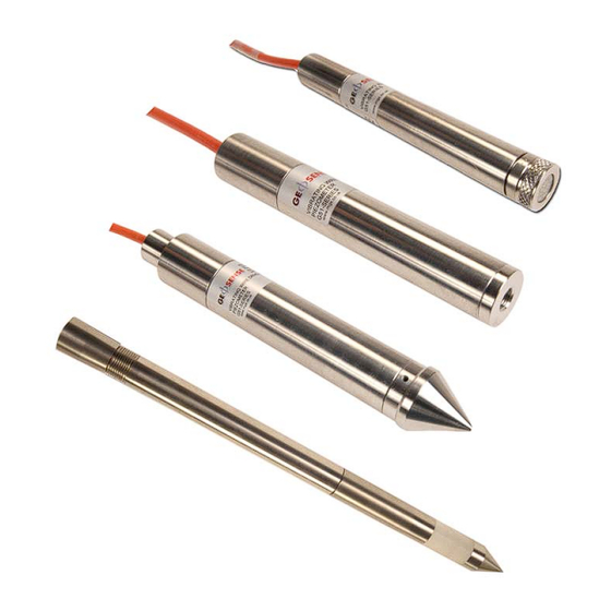
Version 1.4 May 09 1.0 INTRODUCTION This manual is intended for all users of Vibrating Wire Piezometers manufactured by MGS Geosense and provides information on their installation, operation and maintenance. It is VITAL that personnel responsible for the installation and use of the piezometers READ and UNDERSTAND the manual, prior to working with the equipment. - Page 4 They are also somewhat tolerant of damp wiring conditions and resistant to interference from external electrical noise. The MGS-Geosense range of VW piezometers is supplied in various configurations to suit varying installation environments and techniques. Each VW piezometer is fitted with a length of connecting cable, an internal temperature sensor and a surge arrestor.
-
Page 5: Theory Of Operation
( the sensing element ) and at the other end to the Nimonic inner body, all sealed into a stainless steel body. The internal parts of all MGS Geosense piezometers are identical, only the thickness of the diaphragm and the geometry of the body changes. -
Page 6: Conformity
Document Number QF037 (Iss 2) We Marton Geotechnical Services Ltd at above address declare under our sole responsibility that the Geosense products detailed below to which this declaration relates complies with protection requirements of the following harmonized EU Directives, Low Voltage Directive 73/23/EEC (as amended by 93/68/EEC) -
Page 7: Markings
Version 1.4 May 09 3.0 MARKINGS Geosense piezometers are labelled with the following information:- Manufacturers name & address Product type Model Serial number CE mark... -
Page 8: Delivery
Piezometers manufactured by MGS Geosense. 4.1 Packaging VW Piezometers are packed for transportation to site. Packaging is suitably robust to allow normal handling by transportation companies. Inappropriate handling techniques may cause damage to the packaging and the enclosed equipment. The packaging should be carefully inspected upon delivery and any damage MUST be reported to both the transportation company and MGS Geosense. -
Page 9: Storage
If these ‘out of the box’ CHECK readings show significant differences ( +/- 40 digits ) to the zero pressure values on the calibration sheets, contact MGS Geosense for assistance. ( It should be noted that the ‘CHECK Readings WILL be affected by the atmospheric pressure & altitude ). - Page 10 Version 1.4 May 09 may cause damage to the diaphragms if the water they contain is allowed to freeze. Storage areas should be free from rodents as they have been known to damage connecting cables. No other special requirements are needed for medium or long-term storage although temperature limits should be considered when storing or transporting associated components, such as readout equipment.
-
Page 11: Installation
5.0 INSTALLATION This section of the manual is intended for all users of Vibrating Wire Piezometers manufactured by MGS Geosense and is intended to provide guidance with respect to their installation. It must be remembered that no two installations will be the same and it is inevitable that some ‘fine tuning’... - Page 12 Version 1.4 May 09 The ‘on-site’ BASE readings for the Vibrating Wire Piezometer should be obtained as follows: Fill a large bucket with clean, potable water, ideally of a temperature close to that of the groundwaterr temperature. Ensure that the bucket is away from any heat sources and shaded from the sun.
- Page 13 Version 1.4 May 09 (Continued from page 12) Turn on the readout. Holding the piezometer cable, lift the transducer out of the bucket, allowing it to hang vertically downwards and immediately record 2 or 3 readings. Replace the transducer in the water as before. After one minute of immersion, repeat and record another set of readings.
- Page 14 Version 1.4 May 09 (Continued from page 13) 13. Store the piezometer in water until ready for installation ( or repeat the above just prior to installation )
-
Page 15: Preparation For Installation
Version 1.4 May 09 Preparation for Installation Prior to installation of a piezometer it is essential to establish and confirm details of the installation to be carried out. Some of the main considerations are listed below :- Intended elevation and depth to Piezometer? This can be calculated as either the depth below a known level ( ground level for example ) or as the elevation with respect to a remote datum. - Page 16 Version 1.4 May 09 (Continued from page 15) mechanically ). In a location where high permeability material is present, a sand pocket type installation is preferred. Where a piezometer is to be installed in a material with a low permeability, it is normally better pushed into a pre-formed pocket to maintain intimate contact with the surrounding material.
- Page 17 Version 1.4 May 09 10m is commonly applied (available on request). Tools. Obtain any tools necessary to carry out the installation. The following is a brief list of tools typically used during the installation of Vibrating Wire Piezometers. Fibre measuring tape with a weight added to the end for borehole depth •...
-
Page 18: Installation Procedures - Boreholes
There are many approaches to piezometer installation and, in addition to these broad installation guidelines, MGS Geosense are committed to providing technical support to help engineers and techni- cians tune their procedures to match particular site conditions and requirements. - Page 19 Version 1.4 May 09 (Continued from page 18) Check the drill hole to ensure that the full depth is clear and free of obstructions and that any casing can be withdrawn. CHECK BASE READING OF PIEZOMETER. Where necessary, record a reading from the piezometer to confirm that it has not been damaged since establishing the base readings ( see Section 5.1 )
- Page 20 Version 1.4 May 09 (Continued from page 19) 10. With the filter securely fitted to the piezometer, lower it slowly down onto the sand at the base of the borehole and record another check reading. 11. If necessary, coil up and feed the piezometer cable into the casing so that the drilling rig can be used to retract the casing.
- Page 21 ( In a 100mm diameter borehole the 5kg of ® Geosense Mikolit Bentonite pellets will produce a seal approximately 500mm long ) 14. Fill the remaining void with Grout as shown in the grouting procedure ( See Section 5.6 ).
- Page 22 Version 1.4 May 09 5.3.2 Open ( Un-cased ) Boreholes. When forming a borehole for instrument installation, it may not be necessary to use a temporary steel sleeve or ‘casing’ to hold the hole open during drilling and installation operations. These holes may be described as ’open holes’. The following describes a series of steps that could be adopted to carry out a piezometer installation in an open or uncased borehole.
- Page 23 Version 1.4 May 09 (Continued from page 22) 12. Add a Bentonite seal of specified thickness. This should comprise Bentonite pellets / balls as described above for the base plug. Once borehole is sealed to the specified thickness, check piezometer readings again. 13.
- Page 24 This adaptor is a purpose built component, normally manufactured by MGS Geosense, that can be supplied or modified to suit the size and thread of the drilling rods to which it will be connected. There are two types of pushing adaptor to match the two models of Push-in Vibrating Wire Piezometers supplied by Geosense.
- Page 25 Version 1.4 May 09 (Continued from page 24) As the rods are lowered into the borehole, the cable must be restrained to prevent the piezometer dropping out of the shoe and to maintain control of the cable. Never rotate the lower rods when adding further rods. This may cause the piezometer cable to become wrapped around the rods and will result in a failed installation due to either cable damage or pulling the piezometer back out of its...
- Page 26 Version 1.4 May 09 5.3.4 Borehole Installation (Fully Grouted Method) This is an alternative method of installing either single or multiple piezometers in a single borehole. Rather than creating a filter pocket or pushing the tip into the parent material, the piezometers are suspended in a borehole and the borehole is backfilled with only a suitable Cement &...
-
Page 27: Installation Procedures - Trenches & Pockets
Version 1.4 May 09 5.4 Installation Procedures - Trenches and Pockets This type of installation is carried out where the intended piezometer position is accessible. Commonly this would be during the construction of a structure where the piezometer would form part of a future monitoring regime. Typically this might include embankments, culverts, cut &... - Page 28 Version 1.4 May 09 (Continued from page 27) Create a small pocket ( minimum 300mm x 300mm x 300mm ) into which the piezometer can be installed. Check the elevation of the pocket to ensure that the piezometer will be installed at the correct level. Where the excavation is in a granular material, place a layer of Geotextile material in the base and up the wall of the excavation, then a 100mm layer of graded sand in the base of the trench and pocket.
- Page 29 Version 1.4 May 09 5.4.1 Impermeable Material Once the cable route has been defined, excavate a trench ( minimum 200mm deep ) along the route from the piezometer installation location to the intended cable termination point. Where compaction of backfilled material is critical, the trench should have sides raked at an angle of a minimum 45 degrees.
- Page 30 Version 1.4 May 09 (Continued from page 29) container. Check the function of the piezometer prior to its installation, using a portable readout. Carefully remove the piezometer from the water filled container and place it in the pocket or into the socket, as shown in the sketches. Coil the cable in the pocket, forming a loop as shown.
-
Page 31: Installation Procedures - Observation Wells Or
Version 1.4 May 09 5.5 Installation Procedures - Observation Wells or as Water Level Transducer Vibrating Wire Piezometers can be installed in Observation Wells or Standpipe Piezometers to monitor water levels. It must be remembered that the standard piezometer is a sealed unit and is, therefore, sensitive to any pressure on its diaphragm. -
Page 32: Grouting
Version 1.4 May 09 5.6 GROUTING Backfilling of boreholes and other excavations for piezometer installation often calls for the preparation and installation of a grout. Grout should be mixed in a purpose designed grout mixer so as to ensure a complete mix. -
Page 33: Data Handling
The can then be used to assess any temperature effects on the pressure readings. 6.1.1 Portable Readouts Geosense offer a range of readout and data logging options. Specific operation manuals are supplied with each readout device. Below is a brief, step-by-step procedure for use with the RST VW2106 portable readout. -
Page 34: Data Reduction
Ltd and DataTaker Ltd. These are the most commonly adopted third party manufacturers of data loggers that can be used with Vibrating Wire Instruments. Specific configuration and programming advice can be obtained from Geosense and or the manufacturers documentation. Data Reduction... - Page 35 An instrument calibration sheet similar to the example in the appendix of this manual includes the following information: Model This refers to the Geosense or RST model number. Serial Number This is a unique sensor identification number that can be found on the cable just behind the piezometer body and, for long cables, at the end of the cable.
- Page 36 Version 1.4 May 09 (Continued from page 35) and Polynomial for comparison with the actual Applied Pressure. Non Lin. % fso Non Linearity expressed as a percentage of the transducers Full Scale. Calibration Factors ‘Linear’ and ‘Polynomial’ factors are provided for a selection of engineering units ( other units can be calculated directly from the kPa values ).
- Page 37 Version 1.4 May 09 (Continued from page 36) Barometric Pressure Considerations In some locations, barometric pressure varies only a little, except when there are storms. In other locations, normal weather may bring barometric pressure changes as large as 34 mb (0.5 psi) during a day, and 68 mb (1 psi) during a year. If a piezometer is sealed into a borehole to measure pore-water pressure, the only pressure acting on the piezometer’s diaphragm is the water pressure at that depth, so a barometric correction need not be applied.
- Page 38 Version 1.4 May 09 (Continued from page 37) Example Zero Reading in Linear Digits 9555.5 Atmospheric Pressure when Zero recorded 1022mb Current Reading in Linear Digits 9244.3 Current Atmospheric Pressure 1007mb Calculated water pressure in mH O ( see prev. section ) 5.651m Change in Atmos Pressure ( Current - Zero ) 1007 - 1022 mb...
-
Page 39: Maintenance
Version 1.4 May 09 MAINTENANCE The Vibrating Wire piezometer is a maintenance free device for most applications. This is because it is intended for sub-surface installation and would normally be irretrievably sealed into boreholes or fill materials. However, when the piezometer is installed in a location where a flow of water moves past it and it can be recovered, a check should be made to determine the condition of the filter. - Page 40 Version 1.4 May 09...
-
Page 41: Specification
Version 1.4 May 09 9.0 SPECIFICATION VWP-3000 series Type VWP-3000 VWP-3001 VWP-3100 VWP-3101 VWP-3200 VWP-3201 VWP-3300 Filter Type Length mm Diameter Resolution ±0.025% Full Scale Accuracy ± 0.1% Full Scale Thermal Effect Less than 0.02% Full Scale per C ** Operating Range -20 to + 80 Over Range Capacity... -
Page 42: Spare Parts
HAE (High Air Entry) filter assembly. Civil engineering sites are hazardous environments and instrument cables can be easily damaged if they are not adequately protected. Geosense can therefore provide the following parts that may be required to effect repairs to instrument cables: PU coated 4 Core cable with foil shield and copper drain. -
Page 43: Return Of Goods
(please contact MGS Geosense for details). Inspection & estimate It is the policy of MGS Geosense that an estimate is provided to the customer prior to any repair being carried out. A set charge for inspecting the equipment and providing an estimate is also chargeable. -
Page 44: Limited Warranty
Sufficient site data has been provided to MGS Geosense by the purchaser as regards the nature of the installation to allow MGS Geosense to select the correct type and range of Vibrating Wire Piezometer and other component parts. -
Page 45: Appendix
Version 1.4 May 09 12.0 APPENDIX VW piezometer specification Mikolit™ specification Bentonite specification Sample VW piezometer calibration sheet... - Page 46 Version 1.4 May 09 Geosense is a division of Marton Geotechnical Services Ltd Geotechnical Centre . Rougham Industrial Estate . Rougham . Bury St Edmunds . Suffolk . IP30 9ND . England . Tel: +44 (0) 1359 271167 . Fax: +44 (0) 1359 271168 . email: info@mgs.co.uk . www.mgsgeosense.co.uk...
Need help?
Do you have a question about the VW PIEZOMETERS and is the answer not in the manual?
Questions and answers