
Subscribe to Our Youtube Channel
Related Manuals for Geosense HLC 6000 Series


Summary of Contents for Geosense HLC 6000 Series
- Page 1 V1.0 July 2020 HYDRAULIC ANCHOR LOAD CELLS HLC 6000 SERIES...
- Page 2 V1.0 July 2020...
-
Page 3: Table Of Contents
V1.0 July 2020 CONTENTS PAGE INTRODUCTION General description Theory of operation CONFORMITY MARKINGS DELIVERY Packaging Handling Inspection/functionality 4.3.1 VW transducer 4.3.2 Pressure gauge/manometer Storage INSTALLATION General issues General considerations Mounting surfaces Installation DATA HANDLING Monitoring the load cell readings Portable readouts Data reduction 6.3.1 Overview... -
Page 4: Introduction
® This manual is intended for all users of Geosense HLC-6000 series load cells manufactured by Geosense and provides information on their installation, operation and maintenance. It is VITAL that personnel responsible for the installation and use of the Geosense® Hydraulic Load Cells READS and UNDERSTANDS the manual, prior to working with the equipment. -
Page 5: Conformity
Tel: +44 (0)1359 270457 www.geosense.co.uk Declaration of Conformity We Geosense Ltd at the above address declare that the equipment detailed below complies with the requirements of the following EU Directive:- The Electromagnetic Compatibility Directive 2014/30/EU Restriction on the use of certain Hazardous Substances RoHS2 2017/2102/EU Waste electrical &... -
Page 6: Markings
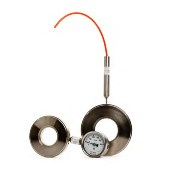
V1.0 July 2020 3.0 MARKINGS Geosense HLC-6000 Series Hydraulic Anchor Load Cells are labelled with the following information:- Manufacturers name & address Product Type/Model Range Serial number CE mark WEEE mark HLC-6500 with VW Transducer HLC-6000 with Manometer... -
Page 7: Delivery
They and their associated equipment should always be handled with care during transportation, storage and installation. ® Once the shipment has been checked it is recommended that Geosense Vibrating wire load cells remain in their original packaging for storage or transportation. -
Page 8: Pressure Gauge/Manometer
Section 9) within +/- 50 digits after barometric and temperature corrections are made. ® The elevation of the Geosense factory is +60 metres above sea level and barometric pressures change with altitude by approximately 1.2kPa per 100 metres. 4.3.2 Pressure gauge/manometer Check the gauge offset is at zero The ‘CHECK Readings WILL be affected by changes in... -
Page 9: General Issues
(anchor or rod). Very stiff abutment plates and load distribution plates is recommended. The abutment plate (provided locally) is normally made to suit specific site requirements and the load distribution plate (supplied by Geosense) should be I inserted between the load cell and the anchor head (see next page) - Page 10 V1.0 July 2020 5.3 Mounting surfaces contd… Details shown below are for a typical installation but conditions may vary from site to site. Before installing the following conditions should apply The applied load must be perpendicular, centered, and uniform over the Load Cell surface.
- Page 11 V1.0 July 2020 5.4 Installation STEP 1 Place the Bearing Plate (optional) over the tensioning member(s) and onto the loading surface abutment plate STEP 2 Lower the Load Cell over the tensioning member(s) and onto the loading surface (abutment plate) TAKE A ZERO LOAD READING (SEE DATA HANDLING FOR VW) STEP 3 Lower the Distribution Plate over the tensioning member(s)
- Page 12 V1.0 July 2020 5.4 Installation contd... STEP 4 Place the Wedge Plate over the tensioning member(s) and onto the load distribution plate and additional top load plate (optional) STEP 5 Slowly lower the tensioning jack over the tensioning member(s)
- Page 13 V1.0 July 2020 5.4 Installation contd... STEP 6 Carefully lower the tensioning Jack onto the load distribution plate or top load plate where applicable STEP 7 Tension the strands as required and take readings from the VW transducer or manometer as necessary TAKE CARE NOT TO OVER RANGE THE LOAD CELL If required protect the installation with a suitable cap...
-
Page 14: Data Handling
(see section 6.6). Portable Readouts Geosense offer a range of readout and data logging options. Specific operation manuals are supplied with each readout device. ® Below is a brief, step-by-step procedure for use with the Geosense VWR-1 portable readout. -
Page 15: Data Reduction
For most Vibrating Wire sensors, these factors are unique and are detailed on the individual sensor calibration sheets. A unique calibration ® sheet is supplied with every Geosense Vibrating Wire Transducer. If the readout displays ‘Frequency’ values, (e.g. 2768.5 Hz) only a simple calculation is re- quired to convert the readings to Linear Digits. - Page 16 An instrument calibration sheet similar to the example in the Section 6.6 of this manual in- cludes the following information: Model This refers to the Geosense model number. Serial Number This is a unique sensor identification number that can be found on the load cell body and, for long cables, at the end of the cable.
-
Page 17: Calibration
V1.0 July 2020 6.5 CALIBRATION Vibrating Wire... - Page 18 V1.0 July 2020 6.5 CALIBRATION contd... Pressure gauge/Manometer...
-
Page 19: Temperature Considerations
For further discussion about ‘No load”, load cells please contact ® Geosense For HLC-6000 series load cells fitted with a manometer engineering judgement will be required to understand any temperature effects. -
Page 20: Maintenance
V1.0 July 2020 MAINTENANCE ® Geosense HLC-6000 Series Hydraulic Anchor Load Cells are basically maintenance free device for most applications but the following should be considered during the service life:- Keep away from direct sunlight to avoid large thermal affects •... - Page 21 V1.0 July 2020 8.0 TROUBLESHOOTING contd... The ram size varies from the load cell size This causes bending of the distribution plate which in turn causes over or under measurement of load depending on the ratios on the cell to jack area. There are two feasible ways to overcome this:- i) Match the cell and jack ram sizes to each other.
- Page 22 V1.0 July 2020 8.0 TROUBLESHOOTING contd... It is generally accepted that when a Vibrating Wire instrument is producing a stable reading on a suitable readout, the value will be correct. Only on very rare occasions will this be untrue. In almost all cases, a fluctuating reading is a sign of a faulty signal from the sensor. The fault could be in either the sensor, the connecting cable, any switch boxes or the readout.
-
Page 23: Specification
DIMENSIONSI (other available on request) Capacity (kN) Internal Outside Load Cell Height Load distribution diameter (mm) Diameter (mm) (mm) plate height (mm) 1000 1500 2000 10.0 SPARE PARTS ® Geosense HLC-6000 Series load cells do not have any replaceable parts. -
Page 24: Return Of Goods
® In order to make a warranty claim, contact Geosense and request a Returned Equipment Report Form QF034. Tick the warranty claim box and return the form with the goods as above. -
Page 25: Limited Warranty
Purchaser by the Manufacturer. ® The Purchaser assumes all risks and liability whatsoever in connection with the Geosense HLC-6000 Series Hydraulic Anchor Load Cells from the time of delivery to Purchaser. - Page 26 V1.0 July 2020 VIBRATING WIRE ANCHOR LOAD CELLS HLC-6000 SERIES...
Need help?
Do you have a question about the HLC 6000 Series and is the answer not in the manual?
Questions and answers