AGREEMENT CONDITIONS – COMAP CONTROL SYSTEMS SOFTWARE” (License Agreement) and/or in the “ComAp a.s. Global terms and conditions for sale of Products and provision of Services” (Terms) and/or in the “Standardní podmínky projektů komplexního řešení ke smlouvě o dílo, Standard Conditions for Supply of Complete Solutions”...
Page 6
ComAp, but by following them the cyber-attacks can be considerably reduced and thereby to reduce the risk of damage. ComAp does not take any responsibility for the actions of persons responsible for cyber-attacks, nor for any damage caused by the cyber-attack.
IL-NT FCM IL-NT RS232-485 IC-NT RD IC-NT-RD-1.0-New Features Note: # IL only MRS15, MRS16, AMF25 * only InteliLog Note: For connecting with controller and unit reprogramming, see Proprietary controller guide. Accessory Modules for IL-NT, IC-NT, IA-NT and ID-Lite Global Guide...
InteliSys-NT controller Supported CAN1 line Supported CAN2 line Supported CAN1and CAN2 line Supported USB Supported Ethernet Supported RS232 line Supported RS485 line Module has analog inputs Module has digital inputs Accessory Modules for IL-NT, IC-NT, IA-NT and ID-Lite Global Guide...
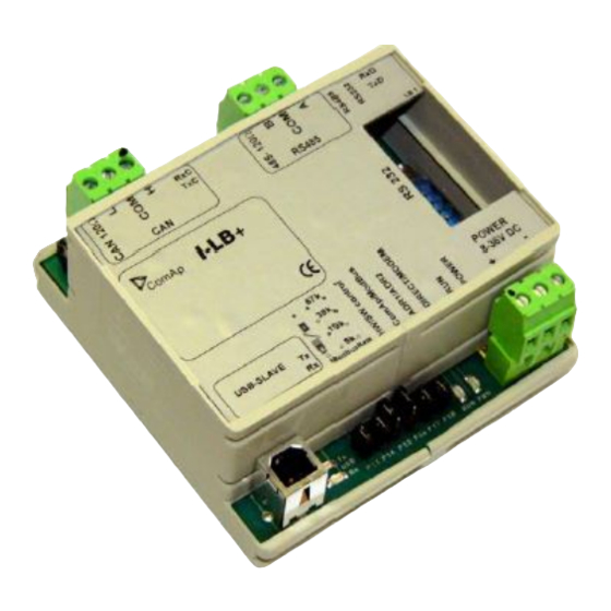
57600 bps (IG-MU only 19200 bps). I-LB/I-LB+ can be connected with PC via USB, RS232 or RS485. I-LB is without USB port, I-LB+ is with USB port (speed ≈ 115200 bps). Unit is 35 mm DIN rail mounted. Accessory Modules for IL-NT, IC-NT, IA-NT and ID-Lite Global Guide...
Select RS mode (P3) Jumper P3 selecting RS mode. When jumper P3 is connected to 1-2, RS232 mode is activated. When jumper P3 is connected to 2-3, RS485 mode is actives. Accessory Modules for IL-NT, IC-NT, IA-NT and ID-Lite Global Guide...
Page 12
ComAp / Modbus (P16) Jumper P16 selects between ComAp PC tools (InteliMonitor, WinScope, et al.) and third party PC SW for monitoring with Modbus interface. ComAp PC tools are selected when P16 is opened; Modbus is selected when P16 is closed.
Page 13
ADR1/ADR2 – selection between two available modem communication channels; IG/IS-NT controllers only Setting RS232/RS485 jumper to RS232 position is obligatory Modbus (not available at USB port of I-LB+, USB port always works in ComAp mode) DIRECT RS232/RS485 – selection of serial communication type ADR1/ADR2 –...
I-LB+ has to be connected to modem via standard modem cable (full RS232) where the DSR (Data Set Ready) signal detects modem presence (when MODEM (HW) type selected). Three-wire RS232 cable (TxD, RxD, GND) can be used (e.g. for GSM modems) when MODEM (SW) type is selected. Accessory Modules for IL-NT, IC-NT, IA-NT and ID-Lite Global Guide...
Page 15
It is necessary to select which connection type(s) particular I-LB+ is using. Available combinations of I-LB+ modules There are four of communication channels available on the CAN2 link at the same time. Accessory Modules for IL-NT, IC-NT, IA-NT and ID-Lite Global Guide...
Max. 300 ms Current consumption 100mA at 24 V Storage temperature - 40 °C to + 80 °C Operating temperature - 30 °C to + 70 °C 6 back to I-LB+ Accessory Modules for IL-NT, IC-NT, IA-NT and ID-Lite Global Guide...
Note: Unit is 35 mm DIN rail mounted. 4.2.2 Connectors POWER in Power supply from battery POWER out Power supply to controller Accessory Modules for IL-NT, IC-NT, IA-NT and ID-Lite Global Guide...
8 to 36 V DC Storage temperature - 40 °C to + 80 °C Operating temperature - 30 °C to + 70 °C Image 4.1 Voltage dip recovery 6 back to i-LBA Accessory Modules for IL-NT, IC-NT, IA-NT and ID-Lite Global Guide...
Relay board contains 8 or 16 relays for binary (open collector) output separation. All relays are placed in sockets. I-RB8 I-RB16 I-RB8-231 I-RB16-231 Number of relays Nominal voltage [V] DC Maximal load 16A resistive load, 4A inductive load Accessory Modules for IL-NT, IC-NT, IA-NT and ID-Lite Global Guide...
Each relay has LED which lights when n.o. relay’s connector is closed. This LED is dark when n.o. relay’s connector is open. I-RB8, I-RB8-231 has 8 LEDs and I-RB16, I-RB16-231 has 16 LEDs. 4.3.4 Wiring Image 4.3 Relay-connector connection Accessory Modules for IL-NT, IC-NT, IA-NT and ID-Lite Global Guide...
Contacts protection varistor 14DK390 Storage temperature - 40 °C to + 80 °C Operating temperature 30 °C to + 70 °C Note: * - only I-RB8-231, IRB-16-231 6 back to I-RB8/I-RB16/I-RB8-231/I-RB16-231 Accessory Modules for IL-NT, IC-NT, IA-NT and ID-Lite Global Guide...
IG-IOM modules are I/O extension modules equipped with 8 binary inputs, 8 binary outputs, 4 analog inputs and one analog output. The module can be used for only MRS15/16 and AMF 25 from IL-NT family. Binary inputs and outputs are configurable the same way like inputs and outputs on controller.
4.4.5 LED indication Binary inputs Each binary input has LED which indicates input signal. LED is shining when input signal is set, and LED is dark while input signal has other state. Accessory Modules for IL-NT, IC-NT, IA-NT and ID-Lite Global Guide...
4 % ± 2 ohm out of measured Resistance measurement tolerance value Analog output Output current 0 to 20 mA (Not electric separated) resolution 10 bit Power supply 8 to 36 V DC Accessory Modules for IL-NT, IC-NT, IA-NT and ID-Lite Global Guide...
Page 25
Current cons 100 mA at 24V ÷ 500 mA Storage temperature - 40 °C to + 80 °C Operating temperature - 30 °C to + 70 °C 6 back to IG-IOM Accessory Modules for IL-NT, IC-NT, IA-NT and ID-Lite Global Guide...
IGS-PTM is modification of standard IG-IOM module with four analog inputs, which can be configured for range: 0 – 250 Ω (suitable for Pt100, Ni100) 0 – 100 mV 0/4 – 20 mA 4.5.2 Dimensions Note: Unit is 35 mm DIN rail mounted. Accessory Modules for IL-NT, IC-NT, IA-NT and ID-Lite Global Guide...
Long wires resistance compensation Note: Configuration jumpers IGS, ADR1, ADR2 are OPEN by default. CAN_R jumper is CLOSE by default (IG-IOM mode). Analog inputs are configured for resistance measurement by default. Accessory Modules for IL-NT, IC-NT, IA-NT and ID-Lite Global Guide...
250 Ohm, what in fact corresponds to the 100 mV real measurement range. See example in the picture for converting 100 mV measured voltage to 24 V converted value, displayed on controller screen. Accessory Modules for IL-NT, IC-NT, IA-NT and ID-Lite Global Guide...
Page 29
Table 4.1 Table of conversion Pt100 or Ni100 resistance to temperature Current conversion table Voltage conversion table Current conversion table 20 mA/20.0 mA 100 mV/100.0 mV 20 mA/100.0 Primary Converted Primary Converted Primary Converted Accessory Modules for IL-NT, IC-NT, IA-NT and ID-Lite Global Guide...
Each binary input has LED which indicates input signal. LED is shining when input signal is set, and LED is dark while input signal has other state. Binary outputs Binary output LED shining when binary output is set. Accessory Modules for IL-NT, IC-NT, IA-NT and ID-Lite Global Guide...
One flash and pause – compensation fail. Three flashes and pause – compensation success. Measured lead’s resistance is stored in EEPROM memory (separate value for each input) and is subtracted from measured value when resistance measuring. Accessory Modules for IL-NT, IC-NT, IA-NT and ID-Lite Global Guide...
Current consumption 100 mA at 24V ÷ 500 mA Storage temperature -40 °C to + 80 °C Operating temperature - 30 °C to + 70 °C 6 back to IGS-PTM Accessory Modules for IL-NT, IC-NT, IA-NT and ID-Lite Global Guide...
4.6.2 Connectors Input voltage Output voltage 4.6.3 Wiring Connect one or two IG-MTU units to separate generator and Mains/bus voltage from controller. Accessory Modules for IL-NT, IC-NT, IA-NT and ID-Lite Global Guide...
Page 34
Note: IG-MTU-C can be connected only with classical line controllers! We recommend connect IG-MTU and IG-MTU-2-1 only when is needed separated neutral or when is necessary galvanic separate mains/generator and controller. 6 back to Table of modules Accessory Modules for IL-NT, IC-NT, IA-NT and ID-Lite Global Guide...
± 1.5% at 50Hz Conversion accuracy ± 3.0% at 50Hz Storage temperature - 40 °C to + 80 °C Operating temperature - 30 °C to + 70 °C 6 back to IG-MTU/IG-MTU-C/MTU-2-1 Accessory Modules for IL-NT, IC-NT, IA-NT and ID-Lite Global Guide...
4.7 IL-NT-AOUT8 4.7.1 Description Analog output module, optional plug in card IL-NT AOU8 provides eight Pulse-With-Modulation (PWM) outputs. These are intended to drive VDO style analog gauges. This is to provide visual indication of typically ECU values without installing additional sensors on the engine. PWM signal emulates sensor which would be typically mounted on the engine.
4.7.3 Wiring IL-NT-AOUT8 wiring example for Dacon gauges Example of default analog output curves Accessory Modules for IL-NT, IC-NT, IA-NT and ID-Lite Global Guide...
Open collector, max. 0.5A Power supply 12 to 24V DC Storage temperature - 40 °C to + 80 °C Operating temperature - 30 °C to + 70 °C 6 back to IL-NT-AOUT8 Accessory Modules for IL-NT, IC-NT, IA-NT and ID-Lite Global Guide...
4.8 IL-NT-RS232 4.8.1 Description Communication module, optional plug in card IL-NT RS232 provides additional serial interface for controller. 4.8.2 Connectors RS232 RS232 line Programming Accessory Modules for IL-NT, IC-NT, IA-NT and ID-Lite Global Guide...
Interface to controller Direct mounted RS232 Standard RS232 communication interface Storage temperature - 40 °C to + 80 °C Operating temperature - 30 °C to + 70 °C 6 back to IL-NT-RS232 Accessory Modules for IL-NT, IC-NT, IA-NT and ID-Lite Global Guide...
4.9 IL-NT-S-USB 4.9.1 Description Communication module, optional plug in card IL-NT USB provides additional USB interface for controller. 4.9.2 Connectors RS232 line LEDusb Data on USB line (Rx and Tx) BOOT Programming Accessory Modules for IL-NT, IC-NT, IA-NT and ID-Lite Global Guide...
Interface to controller Direct mounted Standard USB communication interface Storage temperature - 40 °C to + 80 °C Operating temperature - 30 °C to + 70 °C 6 back to IL-NT-S-USB Accessory Modules for IL-NT, IC-NT, IA-NT and ID-Lite Global Guide...
Module inputs can be set for voltage or open collector input signal. When jumper P1 is open, module input is sets to voltage input, jumper P2 is closed for open collector input. Jumper P1 configures input 1 and jumper P2 input 2. Accessory Modules for IL-NT, IC-NT, IA-NT and ID-Lite Global Guide...
Setpoint visibility Always Description “Pulses per liter” constant of fuel flow sensor connected to the first pulse input of IL-NT-FCM module. By setting this constant, the propper counting of FuelConH value in values group Fuel Mgmt is provided, showing the hourly fuel consumption.
Setpoint visibility Always Description “Pulses per liter” constant of fuel flow sensor connected to the second pulse input of IL-NT-FCM module. By setting this constant, the propper counting of FuelAutrefTot value in values group Fuel Mgmt is provided, showing the total amount of fuel refilled through this sensor.
4.11 IL-NT-RS232-485 4.11.1 Description The IL-NT-RS–232-485 is a two port module with RS232 and RS485 interfaces at independent COM channels. The RS232 is connected to COM1 and RS485 to COM2. 4.11.2 Connectors COM1 RS232 line COM2 RS485 line P1,P2 Balancing resistor...
- 40 °C to + 80 °C Operating temperature - 30 °C to + 70 °C Note: Communication speed is depends on controller type and its settings. 6 back to IL-NT-RS232-485 Accessory Modules for IL-NT, IC-NT, IA-NT and ID-Lite Global Guide...
4.12.1 Description IL-NT BIO8 is optional plug-in module with 8 binary inputs or 8 binary open collector outputs. In LiteEdit PC tool (version 4.4 and higher) it is possible to easily choose and configure particular I/O will be binary input or output.
4.12.4 Others information This module is configurable in LiteEdit – Modify configuration – Extension plug-in modules – IL-NT-BIO8. 4.12.5 Wiring Accessory Modules for IL-NT, IC-NT, IA-NT and ID-Lite Global Guide...
Max switching current (common) 2.0 A Max switching voltage 36 VDC Storage temperature - 40 °C to + 80 °C Operating temperature - 30 °C to + 70 °C 6 back to IL-NT-BIO8 Accessory Modules for IL-NT, IC-NT, IA-NT and ID-Lite Global Guide...
4.13.3 Address and jumper setting There is no possibility to set address of module. 4.13.4 Others information This module is configurable in LiteEdit – Modify configuration – Extension plug-in modules – IL-NT-BIO8. Accessory Modules for IL-NT, IC-NT, IA-NT and ID-Lite Global Guide...
Page 52
Load consumption level the gen-set has to start at. Function is inactive when PeakAutS/Sdel = OFF. Genset start is PeakAutS/S Del delayed after the consumption of the Load exceeds the PeakLevelStart limit. Accessory Modules for IL-NT, IC-NT, IA-NT and ID-Lite Global Guide...
Page 53
Tells controller to activate protection against power export to the mains. The function limits gen-set requested power to hold import power higher or equal to the setpoint Export kW. DISABLED / ENABLED Accessory Modules for IL-NT, IC-NT, IA-NT and ID-Lite Global Guide...
Defines max limit for export / import in case Export Limit setpoint is set as ENABLED. Negative value means import limit, positive value export limit zero means no export/import. 4.13.5 Wiring Accessory Modules for IL-NT, IC-NT, IA-NT and ID-Lite Global Guide...
Max switching current (common) 2.0 A Max switching voltage 36 VDC Storage temperature - 40 °C to + 80 °C Operating temperature - 30 °C to + 70 °C 6 back to IC-NT-CT-BIO7 Accessory Modules for IL-NT, IC-NT, IA-NT and ID-Lite Global Guide...
4.14 IL-NT-IO1 IL-NT IO1 is optional plug-in card. Through this card controller can drive up to 4 proportional valves and to used 4 additional binary inputs. The 0V (GND) terminal is internally wired with battery minus internally, the 12- 24V (+Ubat) terminal is wired to battery plus power supply of InteliDrive Lite controller.
4.15 IL-NT-AIO IL-NT AIO is optional plug-in card. This card offers additional four analog inputs and one analog output. Analog inputs can be use for different types of sensor (resistive, current and voltage) and variable analog output, which can be used as PWM. Adjustment of extension plug-in module is possible via LiteEdit too.
Fuel solenoid and Stop solenoid control, Emergency stop and Overspeed protection with analog RPM setting. The unit is not a full-featured replacement of InteliDrive Marine unit, it is a module used for increasing reliability of the whole system. Accessory Modules for IL-NT, IC-NT, IA-NT and ID-Lite Global Guide...
4.16.1 Installation and wiring Dimensions Terminals Accessory Modules for IL-NT, IC-NT, IA-NT and ID-Lite Global Guide...
Page 60
Lightening if InteliDrive Marine has failed and the control signals are Red LED operated by RPU No LED lightening if the RPU unit is not operational or connected to power supply Accessory Modules for IL-NT, IC-NT, IA-NT and ID-Lite Global Guide...
Page 61
↓FR (Fault reset) – binary output from InteliDrive Marine unit configured as Fault Reset ↓WD (Watch Dog) – binary output from InteliDrive Marine unit configured as CtrlHeartBeat ↑RPU – Binary input of InteliDrive Marine unit with configured Warning protection to indicate RPU failure Accessory Modules for IL-NT, IC-NT, IA-NT and ID-Lite Global Guide...
At the moment the RPU takes control over engine it keeps the outputs Fuel Solenoid and Stop Solenoid at their original levels before the time of failure of InteliDrive Marine unit. Accessory Modules for IL-NT, IC-NT, IA-NT and ID-Lite Global Guide...
X = (RPMover x Gear teeth)/60 Step 2 According to value X calculated in step 1 select DIP TIME BASE configuration and value C to be used in step 3 from following table: Accessory Modules for IL-NT, IC-NT, IA-NT and ID-Lite Global Guide...
Page 64
Emergency stop button Controller ↓FR (Fault reset) – binary output from InteliDrive Marine unit configured as Fault Reset ↓WD (Watch Dog) – binary output from InteliDrive Marine unit configured as CtrlHeartBeat Accessory Modules for IL-NT, IC-NT, IA-NT and ID-Lite Global Guide...
Page 65
↓SS – Stop Solenoid – binary output from InteliDrive Marine unit configured as Stop Solenoid ↑FS – Fuel Solenoid ↑SS – Fuel Solenoid POWER1 and POWER2 Two independent power supplies 8 .. 36 VDC Accessory Modules for IL-NT, IC-NT, IA-NT and ID-Lite Global Guide...
Need help?
Do you have a question about the IL-NT and is the answer not in the manual?
Questions and answers